Operator's Manual RN° 2-Cycle BACKPACK BLOWER Model No. 316.794790 INCREDI.PULL_ TM UNBELIEVABLE STARTING E A S E _'_ • • • • • • SAFETY ASSEMBLY OPERATION MAINTENANCE PARTS LIST ESPANOL, R 19 CAUTION: Before using this product, read this manual and follow all safety rules and operating instructions. Sears, Roebuck and Co., Hoffman Visit our website" Estates, IL 60179, U.S.A. www.sears.
TABLE OF CONTENTS Safety Rules ....................................... 2 Warranty .......................................... 5 Know Your Unit ..................................... 6 Assembly Instructions ................................ 7 Oil and Fuel Information .............................. 9 Starting/Stopping Instructions ........................ 10 Operating Instructions ............................... 11 Maintenance and Repair Instructions ................... 12 Cleaning and Storage ..................
WHILE OPERATING • Never start or run the unit inside a closed room or building, Breathing exhaust fumes can kill. Operate this unit only in a wellventilated outdoor area. • Wear safety glasses or goggles that are marked as meeting ANSI Z87.1 standards and are marked as such. Wear ear/hearing protection when operating this unit.
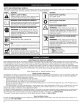
SAFETY AND INTERNATIONAL SYMBOLS This operatorIs manual describes safety and international symbols and pictographs that may appear on this product. manual for complete safety, assembly, operating, maintenance, and repair information. SYMBOL MEANING SYMBOL MEANING • ON!OFF • WEAR EYE AND HEARING WARNING: STOP CONTROL STOP CONTROL | or Caution. May be used in •Indicates SAFETY danger, ALERT warning SYMBOL conjunction with other symbols or pictographs.
Air Filter Cover Starter Rope Handle Choke Lever Fuel Cap Suspension System Stand Shoulder Support Buckle Trigger Lock Waist Support Throttle Cables Waist Support Clip Throttle Grip Flex Tube Trigger Muffler Primer Bulb Blower Tube J Fuel Tank Nozzle
ASSEMBLING THEBLOWER TUBE damage to the unit, shut the unit off before removing installing the blower tubes. WARNING: Toavoid serious personal iojuandor Installing the Flex Tube 1. 2. 3. 4. Place a hose clamp over the end of the Flex Tube (Fig. 1A). Slide the end of the Flex Tube with the clamp on it over the elbow tube (Fig. 1B). Align the bump on the Flex Tube with the bump on the elbow tube (Fig. 1C). Tighten the screw on the hose clamp to secure the Flex Tube to the elbow tube (Fig. 1D).
The completed blower tube should look like Figure 6. Elbow Tube Zip Tie Secure the Throttle Cables Place a zip tie around the elbow tube and the throttle cables (Fig. 7) as shown, making sure not to crimp the cables. Hose Clamp t/ Zip Tie._ Flex Tube Throttle Cables Hose Clamp Zip Tie Fig. 7 On/Off Switch Upper Blower Tube Throttle Grip Adjusting the Handle 1. Rotate the throttle grip counterclockwise around the blower tube until it is pointing directly downward (Fig. 8, A). I _IIL adjust.
OIL AND FUEL MIXING INSTRUCTIONS Old and/or improperly mixed fuel are the main reasons for the unit not running properly. Be sure to use fresh, clean unleaded fuel. Follow the instructions carefully for the proper fuel/oil mixture. Definition of Blended Fuels Today's fuels are often a blend of gasoline and oxygenates such as ethanol, methanol, or MTBE (ether). Alcohol-blended fuel absorbs water. As little as 1% water in the fuel can make fuel and oil separate. It forms acids when stored.
On/Off ventilated outdoor area.Carbon monoxide exhaust WARNING:Operate thisunitoanly ina wellfumescanbelethalinaconfined rea. Trigger_ WARNING: Avoid accidental starting. Make sure you are in the starting position when pulling the starter rope (Fig. 12). To avoid serious injuw, the operator and unit must be in a stable position while starting. To avoid serious personal injuw, make sure that the blower tube is locked in place or firmly installed. Switch > ,oc.
ADJUSTING THESUSPENSION SYSTEM 1. 2. Place the unit's shoulder supports over your shoulders while the unit is behind you. Close the suspension system's waist support by sliding the waist support clips together (Fig. 14, A). A Fig. 17 Fig. 14 NOTE: Make sure the weight of the unit is supported by the waist support (Fig. 15, A). on the hips glasses or goggles, ear/hearing protection, gloves, long pants and long sleeve shirt.
WARNING" To prevent serious injury, never perform maintenance or repairs with unit running. Always service and repair a cool unit, Disconnect the spark plug wire to ensure that the unit cannot start. See Replacing the Spark Plug. MAINTENANCE SCHEDULE Air Filter Locking Tab Back Plate Perform these required maintenance procedures at the frequency stated in the table, These procedures should also be a part of any seasonal tune-up. NOTE: Some maintenance procedures may require special tools or skills.
CARBURETOR ADJUSTMENT The idle speed of the engine is adjustable. An idle adjustment screw is between the air filter cover and the engine starter housing (Fig. 24). Remove Screws Remove Screws Idle Adjustment Screw Fig. 25 4. Fig. 24 NOTE: Careless adjustments can seriously damage your unit. An authorized service dealer should make carburetor adjustments. Check Fuel Old and!or improperly mixed fuel is usually the reason for improper unit performance.
4. 5. Remove the spark arrestor cover. Remove the spark arrestor screen from the spark arrestor cover (Fig. 28). 6. Clean the spark arrestor screen with a wire brush or replace it. 7. Reinstall the spark arrestor screen, spark arrestor cover and screws. CLEANING IA turn your unit off and allow it to cool before you clean WARNING" To avoid serious personal injury, always or service it. Use a small brush to clean off the outside of the unit. Do not use strong detergents.
CAUSE ACTION Empty fuel tank Fill fuel tank with properly mixed fuel Old or improperly mixed fuel Drain gas tank and add fresh fuel mixture Plugged spark arrestor Clean or replace spark arrestor CAUSE ACTION Air filter is plugged Improper carburetor Replace or clean the air filter adjustment Adjust according to the Carburetor Adjustments section or take to a Sears or other qualified service dealer for an adjustment CAUSE ACTION Old or improperly mixed fuel Drain gas tank and add fresh fuel
Engine Type................................................................................................................................................................... Air-Cooled, 2-Cycle Displacement .................................................................................................................................................................. 1.55cuin.(25.4cc) IdleSpeedRPM...............................................................................................................
CALIFORNIA EVAPORATIVE EMISSION CONTROL WARRANTY STATEMENT Your Warranty Rights and Obligations The California Air Resources Board and Sears Brands LLC (Sears) is pleased to explain the evaporative emission control system's warranty on your 2007 model year and later small off-road (equipment type) engine.
Manual del Operador RN° 2-Ciclos SOPLADOR DE MOCHILA Modelo No. 316.794790 INCREDI.PULL_ T_ UNBELIEVABLE STARTING E A S E _'_ • • • • • SEGURIDAD MONTAJE FUNCIONAMIENTO MANTENIMIENTO LISTADO DE PIEZAS PRECAUCION: Antes de utilizar este producto, lea este manual y siga todas las reglas de seguridad y las instrucciones de funcionamiento. Sears, Roebuck and Co., Hoffman Visit our website" Estates, IL 60179, U.S.A. www.sears.
INDICE DE CONTENIDOS Normas para una operaci6n segura .................... E2 Garant[a .......................................... E5 Conozca su unidad ................................. E6 Informaci6n del aceite y del combustible ................ E7 Instrucciones de montaje ............................ E9 Instrucciones de arranque y apagado ................. E10 Instrucciones de operaci6n .......................... E11 Instrucciones de mantenimiento y reparaci6n ........... E12 Limpieza y almacenamiento ....
DURANTE LAOPERACION • No arranque ni opere la unidad en una sala o edificio cerrado. Los gases de escape de mon6xido de carbono pueden ser letales en un Area cerrada. Opere esta unidad s61o en un Area exterior bien ventilada. • Use lentes o gafas de protecci6n que cumplan con las normas ANSI Z87.1, y protecci6n para sus oidos/audici6n mientras opere esta unidad. Use siempre una mascara facial o para protegerse contra el polvo si la operacidn levanta polvo.
• SIMBOLOSDESEGURIDAD E INTERNACIONALES • Este manual del operador describe los simbolos y figuras de seguridad e internacionales que pueden aparecer en este producto. Lea el manual del operador para obtener informaci6n completa acerca de la seguridad, ensamble, operaci6n y mantenimiento y reparaci6n. SYMBOL MEANING SYMBOL MEANING A •SIMBOLO DE ALERTA DE SEGURIDAD I Indica peligrol advertencia o precauci6n. Pued e ser I I utilizado junto con otros s[mbolos o figuras.
Cubierta defiltro Manijadelacuerda deaire dearranque Palanca del obturador Tapadel combustible Sistema de soporte Soportes delos hombros Sopo_e Hebillasdelossoportes delacintura Cablesdel regulador Soportes de lacintura Presillas de lossoportes delacintura Trabadelgatillo Mangodecontrol delregulador Gatillo Silenciador Bombilla del cebador Tubodela sopladora Tanque decombustible •Boquilla E5
ENSAMBLAJE DELTUBODELASOPLADORA graves y daSos a la unidad, apague la unidad antes de DVERTENCIA" Para de evitar lesiones personales quitar o instalar los tubos la sopladora. I_ Instalaci6n del tube flexible 1. Coloque una abrazadera de manguera sobre el extreme del tubo flexible (Fig. 1, A). 2. Deslice el extremo del tubo flexible con la abrazadera colocada sobre la boquilla de la caja de impelente (Fig. 1, B). 3. Alinee el tope del tube flexible con el tope de la boquilla del motor (Fig. 1, C). 4.
El tubo terminado de la sopladora debe parecer come en la Figura 6. Tube del code Abrazadera de la manguera Elbow Tube Asegure los cables del regulador Coloque un cincho de plastico alrededor del tube del codo y los cables del regulador (Fig. 7) como se muestra, asegurandose de no engarzar Clncho los cables.
MEZCLAR ELACEITE Y ELCOMBUSTIBLE ADVERTENCIA" El combustible viejo o mal mezclado son los motivos principales del mal funcionamiento de la unidad. Aseg_rese de usar combustible nuevo, limpio y sin plomo. Siga las instrucciones en detalle para mezclar correctamente el aceite y el combustible. Definici6n de los combustibles de mezcla Los combustibles actuales con frecuencia son una mezcla de gasolina y oxigenantes como por ejemplo etanol, metanol o MTBE (eter).
.j ADVERTENCIA: Use esta unidad s61o en un Area exterior bien ventilada. Los gases de escape de mon6xido de carbono pueden set letales en un Area cerrada. _' _ __ Evite los arranques accidentales. Col6quese en posici6n de inicio cuando tire de la cuerda de arranque (Fig. 12). El operador y la unidad deben estar en una posici6n estable al arrancar la unidad para evitar graves lesiones personales.
AJUSTE DELSISTEMA DESOPORTE 1. 2. Coloque los soportes de la unidad sobre sus hombros mientras la unidad este detras de usted. Cierre los soportes de la cintura del sistema de soporte uniendo las presillas de los soportes de la cintura (Fig. 14, A). A Fig. 17 Fig. 14 NOTA: Asegt_rese de que los soportes de la cintura soporten el peso de la unidad sobre las caderas (Fig. 15, A). A A largos y camisa de manga larga. • Si las condiciones son polvorientas,el operador Ilevapuesta una mascara.
Filtro de aire graves, nunca realice manteni-miento ni reparaciones ADVERTENCIA: Para evitar lesiones personales con la unidad funcionando. Realice siempre el mantenimiento y las reparaciones con la unidad fria. Desconecte el cable de la bujia de encendido para cerciorarse de que la unidad no arrancara. Lea Cambio de la Buj(a de Encendido. PROGRAMA Orejeta ? Bastidor del filtro de aire DE MANTENIMIENTO Lleve a cabo estos procedimientos de mantenimiento requeridos con la frecuencia indicada en la tabla.
AJUSTE DEL CARBURADOR La velocidad mfnima del motor puede ser ajustada. Puede tener acceso al tornillo de ajuste de minima a traves de un orificio en la parte superior de la cubierta del motor (Fig. 24). Saque los tornillos c Saque los Tornillo de ajuste de minima Fig. 25 4. 5. Fig. 24 NOTA: Los ajustes descuidados pueden da_ar su motor seriamente. Los ajustes del carburador deben ser realizados por un proveedor de servicio autorizado.
4. 5. Retire la cubierta del amortiguador de chispas. Saque la pantalla del amortiguador de chispas de la cubierta del amortiguador de chispas (Fig. 28). 6. Limpie la pantalla del amortiguador de chispas con un cepillo de alambre, o cambiela. 7. Vuelva a instalar la pantalla del amortiguador de chispas, la cubierta del amortiguador de chispas y el tornillo.
CAUSA Eltanquedecombustible estavacfo ACClON Lleneeltanqueconcombustible bienmezclado El combustible Drene el tanque es vie]o o esta mal mezclado Parachispas obstruido de gasolina y agregue mezcla de combustible nueva Limpie o cambie el parachispas I =11I_V_ [,]11[,]:t I#[,] Il[IJ #[_ [,] #I'_,_ I=1# _V_ll _II_V_ P'_,W ACClON CAUSA El filtro de aire esta obstruido Cambie o limpie el filtro de aire El carburador Ajuste segOn las instrucciones o Ileve la unidad a un proveedor de servicio autoriz
Tipodemotor................................................................................ Desplazamiento ......................................................................... R.RM.develocidad minima.......................................................................... R.RM.deoperaci6n ................................................................................ Tipodeencendido ........................................................................................ Interruptor deencendido ......
DECLARACION DE GARANTiA DE CONTROL DE EMISIONES EVAPORATIVAS PARA CALIFORNIA Los Derechos y Obligaciones de Usted segOn la Garantia El Consejo de Recursos del Aire (Air Resources Board) de California y Sears Brands LLC (Sears)tienen el placer de explicar la garantia del sistema de control de emisiones evaporativas en su motor "off-road" peque_o (tipo de equipo) modelo del abe 2007 y posterior.
E17
REPLACEMENT PARTS - MODEL 316.794790 2-CYCLE GAS BACKPACK BLOWER Item El8 Part No. Description Item 1 2 753-05631 753-05701 Muffler Assembly (includes 2) Muffler Gasket 3 4 5 753-05636 753-05784 753-05702 Shortblock Assembly Spark Plug Insulator Gasket 6 7 753-05632 791-181709 Insulator Assembly Carburetor Gasket 8 9 753-05633 791-181757 Carburetor Air Filter (includes 4 & 11-17) (includes 5) Assembly (includes 7) Part No.
REPLACEMENT PARTS - MODEL 316.794790 2-CYCLE GAS BACKPACK BLOWER i Item 1 2 3 4 5 6 7 8 9 10 11 12 13 Part No. 753-05637 753-05638 753-05652 753-05639 753-05640 753-05641 753-05642 753-05655 753-05645 753-05643 753-05644 753-05647 753-05646 Description Nozzle Lower Blower Tube Throttle Grip Assembly Upper Blower Tube Clamp Flex Tube Elbow Harness Clip Harness (includes 8) Lead Wire Throttle Cable Nut Spacer Item 14 15 16 17 18 19 20 21 22 23 24 25 Part No.
Your Home For expert troubleshooting and home solutions advice: II 8 sge www.managemyhome.com For repair - in your home - of all major brand appliances, lawn and garden equipment, or heating and cooling systems, no matter who made it, no matter who sold it! For the replacement parts, accessories and owner's manuals that you need to do-it-yourself. For Sears professional installation of home appliances and items like garage door openers and water heaters.