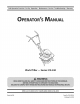
Safe Operation Practices • Set-Up • Operation • Maintenance • Service • Troubleshooting • Warranty L World Tiller m Series 210-240 MTD LLC, P.O. BOX 361131 CLEVELAND, OHiO 44136-0019 PrintedIn USA FormNo.
1 ToTheOwner ThankYou Thank you for purchasing an MTD Garden Tiller. engineered to provide excellent operated and maintained. Please read this entire manual It instructs performance It was carefully prior to operating your machine.
2 importantSafeOperationPractices WARNING! This symbol could endanger all instructions points the personal safety and/or in this manual with these instructions out important before property attempting may result in personal When you see this symbol. safety instructions of yourself to operate which, if not followed, and others. this machine. Read and follow Failure to comply injury.
When practical, e_ equipment 11. After striking dispenser nozzle. 12. Keep the nozzle in contact with the rim of the fuel tank or container at all times until fueling opening complete. Do not use a nozzle lock-open Extinguish all cigarettes, g. Never remove Disengage is handles). device. all clutch levers (if fitted) Engine exhaust indoors. Never over fill fuel tank. Fill tank to no more than 1/2 of filler 15. Use caution when tilling underground utilities. damage i.
9. If the fuel tank has to be drained, 10. Observe proper disposal etc. to protect 11. do this outdoors. laws and regulations the environment. internal According to the Consumer Products Safety Commission (CPSC) and the U.S. Environmental Protection Agency (EPA), this product SparkArrester for gas, oil, _ brushcovered has an Average Useful Life of seven (7) years, or 130 hours of operation.
Safety Symbols This page depicts and describes safety symbols that may appear machine before attempting to assemble and operate. on this product. Read, understand, and follow all instructions on the READ THE OPERATOR'S MANUAL(S) Read, understand, assemble and follow all instructions WARNING-- WARNING-- WARNING--GASOLINE parts. Contact with the rotating parts can amputate parts.
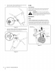
3 Assembly& Set-Up Contents of Carton OneTiller One 20 oz. bottle One Engine Operator's NOTE:The tiller is shipped before operating One Tiller Operator's Manual Manual without Fill up gasoline and oil as instructed manual SAE 30W oil gasoline or oil in the engine. in the accompanying 2. engine Position the upper handle onto the lower handle, Step A in Fig. 3-2. Align the holes on the lower handle with the holes your machine. on the upper handle. Assembly Handle 1.
4. Insert theclutch cablehandle fittingintotheholeonthe rightsideoftheupper handle. SeeFig.3-3. Set-tip (;as & 0il Fill-Up Service the engine separate engine instructions with gasoline and oil as instructed manual in the packed with your tiller. Read the carefully. WARNING! Use extreme care when handling gasoline. Gasoline is extremely flammable and the vapors are explosive. Never fuel machine indoors or while the engine is hot or running.
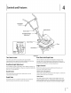
4 Controls and Features Tine Clutch Recoil Starter Clutch Cable Handlebar Height Adjustment De! Rea r Wheel Figure 4-1 TineClutchControl The clutch control Squeezing RearWheelwith DepthStake lever is located the lever against on the upper the handle engages The rear wheel can be raised and lowered handle. storage. the tine drive. Refer to the Maintenance instructions Release the lever to stop the tines from turning.
Operation WARNING! Read, understand, and follow all instructions and warnings posted on the machine and in this manual before operating. WARNING! Be sure no one other than the operator is standing near the tiller while starting the engine or operating the unit. Never run the engine indoors or in enclosed, poorly ventilated areas. Engine exhaust contains carbon monoxide, an odorless and deadly gas. Keep hands, feet, hair and loose clothing away from any moving parts on the engine and the tiller.
In some soils, the desired depth is obtained the first time over the garden. In other soils, the desired depth is obtained by going over the garden two or three times. Passesshould be made across the length and width of the garden alternately. Rocks which are turned up should be removed from the garden area. control by variation of tilling depth and travel speed can be obtained of pressure on the handles.
6 Maintenance& Adjustments WARNING! Before inspecting, cleaning or servicing the tiller, shut off the engine and wait for all moving parts to come to a complete stop. Disconnect spark plug. Failure to follow these instructions properly can result in serious personal property damage. injury the or Wheel Shaft Remove wheel assembly once a season.
DepthStake The depth stake acts as a brake for the tiller and controls the depth and speed at which the machine will operate, Figure 6-2. Remove the clevis and cotter then reattach pins, raise or lower the depth stake, pins to secure. Figure 6-2 Off-SeasonStorage If the tiller will not be used fora period following steps should Clean the exterior thoroughly. Lubrication longer than 30 days, the be taken to prepare the tiller for storage.
7 Service 2. Belt Replacement Your tiller has been engineered with a belt made of special material for longer life and better performance. Replace with a factory-approved purchased your tiller, an authorized 1-800-800-7310 1. OEM belt. See the retailer for information Loosen the lock nut shown in Fig. 7-2. Lock Nut from which you MTD Service Dealer, or call regarding price and availability.
Troubleshooting Problem Engine runs erratic Cause l Remedy 1. Spark plug wire loose 1. Connect and tighten 2. Unit running 2. Move choke lever to OFF on CHOKE 3. Blocked fuel line or stale fuel spark plug wire 3. Clean fuel line; fill tank with clean, fresh gasoline Tines do not engage 4. Vent plugged 4. Clear vent 5. Water or dirt in fuel system 5. Drain fuel tank. Refill with fresh fuel 6. Dirty air cleaner 6. Clean following engine manual 7. Carburetor 7.
9 illustratedPartsList 43_ 13 I 38 2 51 37 18 29 30 26A
Handle,Frame& WheelAssembly Ref, I Part Number 1 649-04030-0638 2 710-0136 3 649-04029-0638 Description Ref, [ Part Upper Handle 29 710-1007 Self Tapping Hex Head Cap Screw, 1/4-20x 1.75 30 911-0415 Clevis Pin Lower Handle 31 710-0809 Self Tapping 737-04272 Pipe Plug, 1/4-18NPT Description Number Screw, 3/8-16 x 1.50 Screw, 1/4-20x 1.25 4 710-04398 Flange Screw, sA6-18x 7.
1
SECTION10- NOTES 19
MANUFACTURER'S LiMiTED WARRANTY The limited warranty set forth below is given by MTD LLC with respect to new merchandise purchased and used in the United States and/or its territories and possessions, and by MTD Products Limited with respect to new merchandise purchased and used in Canadaand/ or its territories and possessions (either entity respectively, "MTD").