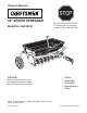
Owner's Manual ® 32" SPIKER SPREADER Model No. 486.24331 CAUTION: Before using this product, read this manual and follow all Safety Rules and Operating Instructions. STOP DO NOT RETURN TO STORE For Missing Parts or Assembly Questions Call 1-866-576-8388 • • • • • Safety Assembly Operation Maintenance Parts Sears, Roebuck and Co., Hoffman Estates, IL 60179 U.S.A. www.sears.com/craftsman PRINTED IN U.S.A. FORM NO. 48070 (REV.
TABLE OF CONTENTS SAFETY RULES........................................................... 3 FULL SIZE HARDWARE CHART................................. 4 CARTON CONTENTS.................................................. 5 ASSEMBLY................................................................... 5 OPERATION............................................................... 12 MAINTENANCE......................................................... 13 STORAGE..........................................................
SAFETY Any power equipment can cause injury if operated improperly or if the user does not understand how to operate the equipment. Exercise caution at all times, when using power equipment. • Read this owner's manual before attempting to assemble or operate the spiker/spreader. • Wear eye and hand protection when handling and using lawn chemicals. • Read the towing vehicle owner's manual and know how to operate the tractor before using the spiker/spreader attachment.
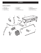
HARDWARE PACKAGE CONTENTS SHOWN FULL SIZE A C B D E H G F J T U S O I Q K L P R M V N NOT SHOWN FULL SIZE GG DD W X Z Y FF CC AA REF. QTY. A 2 B 3 C 2 D 2 E 2 F 1 G 1 H 1 I 1 J 2 K 6 L 10 M 2 N 2 O 2 P 2 Q 4 R 4 HH EE II BB DESCRIPTION Hex Bolt, 1/2" x 4" Hex Bolt, 5/16" x 2-1/4" Hex Bolt, 5/16" x 2" Hex Bolt, 5/16" x 1-3/4" Hex Bolt, 5/16" x 1-1/2" Hex Bolt, 5/16" x 1" Hex Bolt, 1/4" x 1 1/4" Hex Bolt, 1/4" x 3/4" Carriage Bolt.
ASSEMBLY CARTON CONTENTS 1. 2. 3. 4. 5. 6. 7. 8. Chain Cover Flow Control Lever Center Brace Hopper Assembly Hitch Tube (2) Lift Handle Spike Disk (7) Drive Disk Assembly (2) 2 9. Wheel (2) 10. Transport Tube Assembly 11. Hitch Bracket (2) 12.
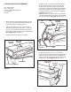
TOOLS REQUIRED FOR ASSEMBLY • • (2) 7/16" Wrenches (2) 1/2" Wrenches (2) 3/4" or Adjustable Wrenches (1) Screwdriver (1) Pliers • • • • Assemble the grip onto the lift handle. See figure 2. On the right side, insert a 5/16" x 1-3/4" hex bolt through a 5/16" flat washer and then through the rear hole in the hopper and the hitch tube. Assemble the transport tube and then the lift handle onto the bolt and secure with a 5/16" nylock hex nut. Do not tighten yet. See figure 2.
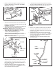
• Fasten the hitch tubes together using three 5/16" x 2-1/4" hex bolts and 5/16" nylock hex nuts. Do not tighten yet. See figure 4. • • 5/16" NYLOCK HEX NUT (3) If the wheel does not spin freely, back off the nylock jam nut and then the plain jam nut 1/4 to 1/2 turn each. Assemble a wheel to the other side. See figure 6.
• • • Place the flow control lever into the slot in the hopper. See figure 8. Place the center brace into the hopper. Insert the 1/4" x 1-1/4" hex bolt through the center brace and the front of the hopper. Assemble a 1/4" flat washer, the flow control lever and a 1/4" nylock hex nut onto the bolt. Do not tighten yet. See figure 8. Insert the 1/4" x 3/4" hex bolt through the center brace and the rear of the hopper. Assemble a 1/4" flat washer and 1/4" nylock hex nut onto the bolt.
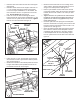
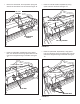
• Push two flange bearings into each of the drive disk assemblies. See figure 11. • DRIVE DISK ASSEMBLY Place a short spacer tube, a drive disk, a 5/8" flat washer, another drive disk and a second 5/8" flat washer onto the shaft. Fit the short spacer tube onto the flanged bearing in the end plate. See figure 14. DRIVE DISKS FLANGED BEARING FLANGED BEARING FIGURE 11 • Push a flange bearing into each of the seven drive disks, from the side shown in figure 12.
• • Place a 5/8" flat washer, the compression spring and another 5/8" flat washer onto the shaft. See figure 16. Place two 5/8" flat washers separated by a long spacer tube onto the shaft. See figure 18. 5/8" FLAT WASHER LONG SPACER TUBE COMPRESSION SPRING 5/8" FLAT WASHER FIGURE 16 FIGURE 18 • • Place two spike disks, separated by a long spacer tube, onto the shaft. Fit the long spacer tube onto the ends of the flanged bearings in the disks. See figure 17.
• • Place two 5/8" flat washers separated by a long spacer tube onto the shaft. See figure 20. • Place a 5/8" flat washer onto the end of the spike disk shaft and secure the shaft with a 1/8" x 1-1/2" cotter pin. See figure 22. Fasten the two drive disks to the shaft using two 1/8" x 1-1/2" cotter pins. See figure 22. 1/8" x 1-1/2" COTTER PIN LONG SPACER TUBE DRIVE DISKS 5/8" FLAT WASHER FIGURE 20 5/8" FLAT WASHER • FIGURE 22 Place a spike disk and a short spacer tube onto the shaft.
OPERATION KNOW YOUR SPIKER SPREADER Read this owner's manual and safety rules before operating your Spiker Spreader. Compare the illustration below with your Spiker Spreader to familiarize yourself with the various controls and their locations. FLOW CONTROL LEVER PLASTIC WING NUT LIFT HANDLE FLOW CONTROL LEVER Opens and closes the flow plate at the bottom of the hopper. PLASTIC WING NUT Tightens at desired setting to control how far the flow control lever can open the flow plate.
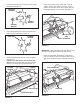
SETTING CHART • MATERIAL Flow Rate Setting TYPE At 3 M.P.H. Fertilizer Granular / Pelleted 5-6 / 6-7 Grass Seed Fine / Coarse 5-6 / 7-8 • • 3 M.P.H. is equivalent to traveling 100 feet in 23 seconds. For easiest application, first apply material across both ends of the area. Two or three passes on each end are sufficient. Then apply material back and forth as shown.
B 42 23 2 14 59 A 7 35 58 1 62 C 10 45 38 44 57 26 A 46 12 59 25 50 5 13 33 41 43 43 44 55 58 58 61 11 63 37 43 9 19 59 54 12 47 59 56 29 53 54 52 16 4 8 6 28 43 42 34 43 60 31 8 3 B F 48 13 20 32 39 59 24 14 13 21 10 59 40 30 58 15 22 17 57 C 42 23 42 18 36 51 27 49 PARTS REPAIR PARTS FOR MODEL 486.
PART NO. DESCRIPTION REF. NO. PART NO. DESCRIPTION Ferrule, 5/16" Thread x 1/4" Hole Bolt, Hex 5/16" x 2-1/4" Bolt, Hex 5/16" x 2" Bolt, Hex 5/16" x 1-1/2" Bolt, Hex 5/16" x 1-3/4" Bolt, Hex 5/16" x 1" Screw, Self Tapping 1/4" x 1" Bolt, Hex 1/4-20 x 3/4" Nut, Nylock Hex 5/16" Nut, Nylock Hex 1/4" Washer, Flat 1/4" Washer, Flat 5/16" Bolt, Hex 1/2" x 4" Full Thread Nut, Hex Jam 1/2" Nut, Nylock Hex Jam 1/2" Pin, Hair Cotter #4 (1/8") Pin, Cotter 3/32" x 3/4" Pin, Flat Head Hitch, 3/8" Dia.
Get it fixed, at your home or ours! Your Home For repair – in your home – of all major brand appliances, lawn and garden equipment, or heating and cooling systems, no matter who made it, no matter who sold it! For the replacement parts, accessories and owner’s manuals that you need to do-it-yourself. For Sears professional installation of home appliances and items like garage door openers and water heaters. 1-800-4-MY-HOME® (1-800-469-4663) Call anytime, day or night (U.S.A. and Canada) www.sears.