Owner's Manua Model No. 320.48251 /k Z___.w CAUTION: Read, understand and follow all Safety Rules and Operating Instructions in this manual before using this product. , SAFETY • OPERATION ° MAINTENANCE "ESPAI_IOL, PAGINA 17 Sears, Roebuck and Co., Hoffman Estates, IL 60179 U.S.A.
Warranty. ............................................................ Page 2 Safety Instructions ........................................... Description ......................................................... Page Page 3 4 Operation ....................................................... Maintenance ...................................................... TroubleShooting ................................................ Service Numbers ...............................................
j manual before using BE this SURE level. Failure all instructions may result in WARNING: to read to andfollow understand all instructions in this radiation exposure, electric shook, fire, and/or bodily injury. hazardous IIIII CAUTION: procedures exposure° I: ............ Use of controls other than those specified CAUTION; or adjustments or performance of herein, may result in hazardous radiation The use of optical instruments with this product will increase eye hazard. are on your level.
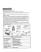
KNOWYOUR LEVEL (See Fig. 1) This Craftsman Laser Trac TM Level is a highly versatile tool. tt can be hand-held, stand_ wall-mounted or leveled on a horizontal surface or tripod it projects a laser line that sweeps a full 90 °, horizontal to vertical and all angles in between. Performance is further.
TO INSTALL BATTERIES (See Figures 2 and 3) This Laser Trac TM Level uses two "AA" batteries, IMPORTANT: BEFORE installing the batteries, ALWAYS check to be sure that the on/off switch on the level is in the up off position (see Fig. 2)° Fig. 2 Fig. 3 up-elf down-on ,2 1. Turn the black battery cover plate on the back of the level 1/4 turn in a counterclockwise direction and remove cover (see Fig. 3). 2, Install the batteries with the polarity as indicated on the label in the battery compartment,, 3.
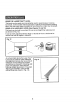
ADJUSTING THE LASER LINE PROJECTION The laser line projected from this tool can be adjusted 90 ° from vertical to horizontal and all angles in between, Use the black finger knob on the top of the tool to adjust angle, 1. Turn the tool on and be careful not to point the tool in the direction of anyone's eyes. 2. Move the finger knob in either direction to change the angle of the laser line on any surface directly in front of the tool. (See Figure 5) Fig.
WORKINGWITH OBSTRUCTIONS AND USER INTERFERENCE (See Figures 8 and 9) Figure 8 illustrates the nature of the laser line projected from the Laser Trac TM Level° It is actually a "plane" of laser light. This is important because obstructions and user interference that takes place in front of the device WILL NOT affect the laser line projected on either side of the user or obstruction.
USING THE LASER TRAC TM LEVEL This level can be easily and conveniently used in several ways, it can be hand-held, wall-mounted with the pin base or placed in the precision leveling base_ Also use tripod base (included) to mount level to a tripod (not included)_ USING AS A HAND-HELD LEVEL (See Figures 12 and 13) This level can be held in one hand for use as a straight line reference tool (as shown in Fig. 12).
USING THE LASER TRAC TM LEVEL (cont.) USING AS A WALL-MOUNTED LEVEL (See Figures 14 to 17) This level can also be wall-mounted using the special base included. Figures 14 and 15 show the top and bottom views of the Thin-Pin Wall-Mount Base° Figure 14 also shows the protective cover that snaps into the bottom of the base when it is not in use. There are two red buttons on the top of the base (see Fig° 14) that are used to push the thin pins out of the base.
USINGTHE LASER TRACTM LEVEL (cont.) MOUNTING LEVEL TO THIN-PIN WALL MOUNT BASE (cont.) WARNING: DO NOT push the red buttons on the Thin-Pin Wall Mount Base unless you plan to affix the base to a soft wood or wallboard surface. This could result in injury, because the pins under the base are very sharp instruments, ALWAYS HANDLE THIS BASE PLATE CAREFULLY. ALWAYS use the protective cover on the base when not in use° Fig. 17 Fig. '16__._.
USING THE LASER TRAC TM LEVEL (cont.) Fig. 18 Fig, 19/_ ve.icaJ Horizontat_ \ Adjustment Knobs Adjustment Knobs / ent Pin I USING LEVEL WITH TRIPOD MOUNTING BASE (see Figure 20) This level can also be used with the Tripod Mounting Base that securely mounts level to any tripod (not included)° This provides even more flexibility in the set up and use of the laser level.
PROJECTING LEVEL VERTICAL LASER LINES (see Figures 2! and 22) When used with the Precision Leveling Base the Laser Trac TM Level will project a plumb vertical line on the surface directly in front of the tool from any angle in the room (see Figure 21). However, if you want to project a straight vertical line across two or more adjacent surfaces (e.i.
This level has been designed to be a tow-maintenancetool However, in order to maintain its performance, you must ALWAYS-follow these simple directions. 1. ALWAYShandle the tool with care°Treat it as you would any optical device, such as a camera or binoculars_ 2. AVOID exposingthe level to shock, continuousvibration or extreme hot or cold temperatures. 3. ALWAYSstore the level indoors, When not in use, ALWAYSstore the level in its protectivecase 4.
PROBLEM CAUSE SOLUTION Laser line projection is weak_ Batteries are weak_ Replace with fresh batteries Laser line is hard to seer Light in area is too bright Use laser enhancing glasses. Laser line is not projected, Power switch is not "on". Check to be sure the power switch cover is in the full down or "on" position. Laser line projected is not level. 1. Thumb knob is not in correct position_ 2, Level is mounted on the thin-pin wall mounting base, 3.
NOTES 15
NOTES 16
iVlanual del Usuario IVEL 4 en 1 con Laser Tr'aCM" Modelo No. 320.48251 /_ ATENCION: Antes de usar este producto, lea, comprenda y siga todas las reqlas de seguridad y las ms-trucciones de funcionamiento incluidas en este manual. ° SEGURIDAD • FUNCIONAMIENTO o rvlANTENIMIENTO Sears, Roebuck and Co., Hoffman Estates, IL 60179 U.S.
Garantfa .......................................................... lnstrucciones de Seguridad .......................... P&gina PAgina Descripci6n ...................................................... Funcionamiento ........................................... Mantenimiento ................................................. P&gina 20 P&ginas 21 - 28 PAgina 29 Soluci6n de Aver[as ......................................... NQmeros de Servicio .......................................
ADVERTENClA: ASEGURESE de leer y comprender todas las instrucciones de seguridad indicadas en este manual,, El incumplimiento de todas las instrucciones indicadas a continuaci6n puede resultar en exposiciSn peligrosa a radiaci6n, choque el6ctrico, incendio yio lesi6n personal. ATENCiON: Et uso de controles o ajustes o la ejecuci6n de procedimientos no especificados en este manual puede resultar en exposici6n pelJgrosa a radiaci6no MlUlIH IIIII HIll U'l....
CONOZCA SU NiVEL (Ver Fig. 1) Este nivel Laser Trac MRCraftsman es una herramienta Puede sostenerse en la mano, montarse horizontal o montar en un trJpode. muy vers&til. en la pared, colocarse Proyecta una linea t&ser que recorre 90 ° completos la vertical y todos los &ngulos intermedios.
INSTALACIONDE LAS PILAS (Ver Figuras 2 y 3) Este nivel Laser Trac MRusa dos pitas "AA". IMPORTANTE: ANTES de instalar las pilas, SlEMPRE compruebe si el interruptor 'on/off' (encendido/apagado) est#. en posiciSn hacia arriba (apagado) (ver Fig. 2)_ Fig. 2 _._ Fig. 3 T 1_ Gire la tapa negra de la _ila situada en la parte trasera vuelta a la izquierda y retire la tapa (ver gig_ 3), del nivel 2. Instate las pilas con la polaridad de la pil& en el compartimiento indicada en la etiqueta 3.
AJUSTE DE LA PROYECCION La linea I&ser proyectada desde esta herramienta puede ser ajustada 90 ° desde ta posici6n vertical a la horizontal yen todos los &ngulos intermedios, Use el bot6n corredizo negro situado en la parte superior de la herramienta para ajustar el &ngulo. 1. Encienda la herramienta y tenga cuidado de no apuntarla a los ojos de nlnguna persona° 2. Mueva el bot6n en cualquier direcci6n para cambiar el &ngulo de la linea I#.
TRABAJANDO CON OBSTRUCCIONES (Ver Figuras 8 y 9) E INTERFERENCIA DEL USUARIO La Figura 8 ilustra la naturaleza de ta linea laser proyectada desde el nivel Trac MR.Es en realidad un "plano" de luz laser.
USO DEL NIVEL LASER TRAC M" Este nivel puede ser f&cil y convenientemente usado de varias manera& Puede ser usado en la mano, rnontado en la pared con la base provista de clavijas delgadas o colocado en la base de nivelaci6n a precisi6n, Adem_ts use ta base para tripode (incluida) para instalar el nivel en un tfipode (no incluido)o USO COMO UN NIVEL DE IVlANO (Ver Figuras 12 y 13) Este nivel puede ser sostenido en una mano para uso como una herramienta de referencia de linea derecha (como se muestra en la F
USO DEL NIVEL LASERTRAC MRcont. USO COMO UN NiVEL MURAL (Ver Figuras 14 a 17) Este nivel tambi_n puede usarse montado en la pared usando la base especial que se incluye. Las Figuras 14 y 15 muestran una vista superior e inferior de la Base de Montaje Mural con Clavijas Delgadas. La Figura 14 tambi6n muestra la cubierta protectora que se coloca a presiSn en la parte inferior de la base, cuando no est_ en uso_ Hay dos botones rojos en la parte superior de la base (ver Fig.
USO DEL NIVEL LASER TRAC MR cont. MONTAJE DEL NIVEL EN LA BASE DE MONTAJE DELGADAS cont. MURAL CON CLAVlJAS ADVERTENCIA' NO oprima los botones rojos situados en la Base de Montaje Mural con Clavijas Delgadas a menos que usted planee instalar la base en una superficie de madera blanda o fibra prensada_ De io contrario, esto podria causar una lesiSn pues las clavijas de la base son muy afiladas. SlEMPRE MANIPULE CON MUCHO CUIDADO ESTA PLACA DE BASE.
USO DEL NIVEL LASER TRAC MRcont. Fig. 18 Perillasde Ajuste Perillasde Ajuste Nineamiento USO DEL NIVEL CON LA BASE DE MONTAJE EN TRIPODE (ver Figura 20) Este nivel tambi6n puede ser usado con la Base de Montaje en Tdpode que permite la instalaci6n del nivet en un tripode (no inctuido), Esto proporciona a_n m&s flexibitidad en el ajuste y uso del nivel l&ser.
PROYECCION DE LINEAS LASER DE NIVELVERTICALES (ver Figuras 21 y 22) Cuando se utiliza con la Base de Nivetaci6n a Precisi6n, el nivel Laser Trac MR proyectar__ una I[nea de nivel vertical a plomo en ta superficie directamente en frente de la herramienta desde cualquier Angulo de la habitaci6n (ver Figura 21). Sin embargo, si usted desea proyectar una linea vertical derecha a trav6s de dos o m&s superficies adyacentes, (por ej.
Este nivel ha sido disefiado como una herramientade bajo mantenimiento. Sin embargo, para mantener su rendimiento,es necesarioque siga SIEMPRE estas sencillas instrucciones. I. SlEMPRE manipule con cuidado la herramienta.Tr&telaigual como trataria cualquier otro dispositivo6ptico, tal como una cAmarafotogr&ficao gemelos binocutares 2. EVITE la exposici6n del nivel a choques, vibraci6n continua o temperaturas extremadamentecalientes o friaso 3.
PROBLEIVlA CAUSA SOLUCION La proyecci6n de la I[nea !_.seres d_biL Las pilas est&n d_biles Cotoque pilas nuevas. Es dificil ver ta linea I_.sero La luz ambiental es dernasiado brillanteo Use lentes de intensificaci6n del l&ser La linea I&ser no se proyecta, El interruptor no est& en la posici6n "on" (encendido). Verifique para asegurarse de que la cubierta del interruptor est6 completamente hacia abajo, en la posici6n "on" (encendido). La linea I&ser proyectada no es nivelada. 1.
NOTAS 31
i ,:,,,,,,_:,,_,iii_"__"_,_"i!_, _, Get ours! it fixed, at yourhome,or Your Home For repair in your home of all major brand appliances, lawn and garden equipment, or heating and cooling systems, no matter who made it, no matter who sold it] For the replacement parts, accessories and owner's manuals that you need to dooit-yourselfo For Sears professional installation of home appliances and items like garage door openers and water heaters. 1-800-4-MY-HOME (1-800-469-4663) e Anytime, (US.A. www.sears.