
Operating instructions


KightFax 811512003 1:18 PAGE 4111 RightFax
DESCRIPTION
The Craftsman 18 Gauge Brad Nailer drives brads from %" to
2%" long. Oiltass design eliminates daily oiling and oil stains
on workpiece. Die cast magnesium body with textured rubber
grip minimizes operator fatigue. I_rga capaoi_ side leading
magazine with posilNe, quick action latch makes loading easy.
Nailer features rear exhaust, single and rapid-fire operation,
adjustable depth of drive control, rubber nose tip and storage
case. Salty feature disabtes toot unless contact tdp is pressed
against workptece. Tapered nosepiece provides operator with
greater visibility for precme fastener placement Rigid nose-
piece reduces jamming. The 18 Gauge Brad Nailer is excellent
for molding, furniture making, and picture fremlng.
SPECIFICATIONS
Capacity .............................. 100 brad nails
Nail size ...................... 18 gauge (.040" x .040 ")
Nail lengths ................................ % to 2_"
Operating pressure ........................ 60-100 PSI
Air inlet.................................... Y,"N.P.T.
Length ........................................ 9Vz"
Height ........................................ 9_ =
Width ......................................... 2_t_,_
Weight ..................................... 2.7 Ibs.
BRAD NAILS
18341 {Box of 5000) ......... 18 gauge brad nails, %" long
19171 {Box of 1000) ......... 18 gauge brad nails, %" long
18342 (Box of 5000) .......... 18 gauge brad nails, 1" long
19172 (Box of 1000) .......... 18 gauge brad nails, 1" long
18343 (Box of 5000) .....
19173 (Box of 1000) .....
18360 [Boo( of 5000) .....
19174 (Box of 1000) .....
18361 (Box of 5000) .....
18362 (Box of 5000) .....
19176 (Box of 1000) .....
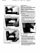
AIR SUPPLY LINE
Rater to Figure 1.
.18 gauge brad nails, 1%" long
18 gauge bred nails, 1%" long
.18 gauge bred nails, 1%" long
• 18 gauge bred nails, 1½" long
• 18 gauge brad nails, 1%" long
... 18 gauge brad nails, 2" long
... 18 gauge brad nails, 2" long
DANGER: Do not use oxygen, carbon dioxide, high-pressure
compressed gas or hotttad gases as the power source for this
tool. The tool will explode and serious personal injury coutd
resutt.
The air tool operates on compressed sir at pressures from
60 to 100 PSI.
Never connect the tool to air pressure which could poten-
tially exceed 200 PSI. Use only clean, dry, regulated air
within rated range as marked on tool.
Air Delivery Required: 0.94 SCFM @ 90 PSI
(30 shots per minute),
WARNING; Keep hands and _ away from discharge area
of tool when connecting air supply. Always disconnect tool
from air supply when servicing or adjusting tool and when tool
Is not in use.
• Air operated tools require cJesn, dry, lubricated com-
pressed air to ensure top performance, low maintenance
and long life.
Dirt and abrasive materials present in all air lines will dam-
age tool O-rings, valves and cylinders.
Moisture will reduce tool performance and life if not
removed from cornprassecl air.
• A filter-ragulator-lubricator system is required and should be
located as dose to tool as possible. A distance of tess than
15 feet is recommended. Lubricator is not required for
oittess tools.
• Keep air filter clean. A dirty filter will reduce the air pressure
to the tool causing a reduction in power and efficiency.
• The air supply system must ha able to provide air pressure
of 60 to 100 pounds per square Inch st tool
• All hoses and pipes In the air supply system must be clean
and free of moisture end foreign pertisies. Hoses must be
rated for s maximum woddng pressure of 150 PSI or 150%
of maximum system pressure, whichever is greater,
• Do n_ mou_ swivel contractor in air supply line.
• The air pressure should be properly regulated,
• Oifferent workptece mate_ls and different fastener lengths
will require different operating pressure.
• Be sure a= conneoitons in air supply system are sealed to
prevent air toss.
• Never connect a female quick-disconnect coupling to the
tool side of air line connection. A male, free-tim coupling
should be connected to the tool side of air freeconnection
(see Figure 1).
WARNING: The female coupling provides a seal preventing
loss of compressed air from compressor tank when discon-
net.fad from msie coupling, if connected to tool s{de of air
supply, the farnate ooupling could seal a compressed air
charge in the tool which could discharge if the tool trigger is
actuated.
Figure I -Air Supply Line
LOADING
Refer to Figures 2, 3 & 4 (page 4).
WARNING: Disconnect tool from air supply. Oo not load tool
until you are ready to use it. Do not ppll trigger or depress
contact tripwhile loading tool. Always load with nose of tool
pointing away from you and others. Always wear ssfaly gog-
gles that comply with United States ANSI Z87.1.
NOTE: For best results, use Sears fasteners only.
3