
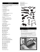
Manual


STEP 10
ATTACH EXTENSION TABLES
Tools Required: 13mm Open End Wrench and Straight Edge
Hardware Required: Six M10 x 25 hex head bolts, six M10
lock washers and six M10 flat washers (Hardware bag #1).
• Assemble extension table to the table using hex head
bolts, lock washers and flat washers.
• Hand tighten only. Do not tighten completely until tables
are level. Use a straightedge to level tables.
• Repeat above procedure for the other extension table.
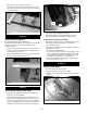
• Use a straight edge to check level and flatness between
main and extension tables.
• After tables are adjusted level and flat, secure the exten-
sion tables by tightening the hex nuts completely.
STEP 11
INSTALL BLADE
Tools Required: 13mm Open end Wrench
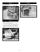
• Loosen knob on right side of cabinet.
• Remove blade and wrench. Replace knob.
• Depress arbor lock and use wrench to loosen flange nut.
Remove flange and nut from arbor.
• Place blade on arbor. Make sure arrow on blade and teeth
point towards front of saw.
• Replace flange and nut on arbor and securely snug blade
in position.
STEP 12
CHECK TABLE ALIGNMENT
• Saws are shipped from the factory with the table adjusted
so the miter gauge slots are parallel to the saw blade.
However, in order to obtain the best results from the saw, it
is suggested this adjustment be checked before operating.
• A simple method of checking alignment is as follows: Bolt
or clamp a dowel rod or similar object to miter gauge (a
combination square can be substituted). Pick out a tooth
on front of blade and set the dowel to it so it is just touch-
ing. Move same tooth to back of blade.
• Gauge this tooth with the dowel rod. If the tooth is in the
same position, relative to the miter gauge slot, the table is
parallel with the blade. In short, the miter gauge slots must
be parallel with the blade. This means that when measur-
ing distance between blade and slot at the front and rear
of the blade, the distances will be equal (see Figure 20).
NOTE: Be positive to measure the distance or make the test
on the same tooth of the saw blade in both front and rear
positions.
• If an adjustment is necessary, proceed as follows: (Refer
to Figure 13 in operator’s manual). Loosen the hex head
bolts and lock washers (Nos. 36, 37 and 38) of the trun-
nion. Shift trunnion until a position is found where the saw
blade is parallel to the miter gauge slots.
NOTE: Saw blade should also be centered within its table
insert opening.
6
Figure 17
Flange
Straight Edge
Nut
Figure 18
Arbor Lock
Figure 19