Operator's Manual 12" MINI LATHE Model No. 351.221060 CAUTION: Read and follow all Safety Rules and Operating Instructions before First Use of this Product. Keep this Manual with Tool. Sears, Roebuck V_N. sear S. CO rn]cra_t and Co., Hoffman Estates, IL 60179 U.S.A.
• Work area should be properly lighted. Warranty ......................................... 2 Safety Rules .................................... 2-3 Unpacking ....................................... 3 Assambl_; ........................................ Installation ...................................... Operation ..................................... Maintenance .................................... • Keep visitors at a safe distance from work area, - Keep chtidren out of workplace.
N_ver turn the lathe ON before clearing the bed, head and taifaiock of all tools, wood scraps, etc., except the workplece and related support devices for the operation planned. Never perform any operation with this lathe where theworkpiece is hand-held. Do not mount a reamer, milling cutter, drill bit, wire wheel or buffing wheel to the headstock spindle. Never place your face or body in line with the chuck or faceplate.
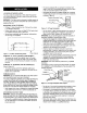
LOCATION OF WOOD LATHE • This tool is equipped with an approved 3-conductor cord rated at 150V and a 3-prong grounding type plug (see F]gure 2) for your protection against shock hazards. • Grounding plug should be plugged directly into a properly installed and grounded 3-prong grounding-type receptacle, as shown (Figure 2). The lathe should be positioned so that neither the operator nor a casual observer is forced to stand in line with the spinning chuck or workpiece.
EXTENSION • • CORDS The use of any extension cord will cause some drop in voltage and loss of power. Wires of the extension cord must be of sufficientsize to carry the current and maintain adequate voltage. Use the table to determine the minimum wire size (A.W.G.) extension cord. • Use only 3-wire extension cords having 3-prong grounding type plugs and 3-pole receptacles which accept the too_plug. • If the extension cord is worn, cut, or damaged in any way, replace it immediately.
CHANGING SPEEDS 3. On one end, make a saw cut approx'_mately l/,s" deep on each diagonal line. This is for the spur center. Refer to Figures 5 and 42. CAUTION: Make sure the power cord is removed from the outlet before attempting to change the belt post_on. 4, The other end uses the bearing center. Place the point of the beating center on the wood where the _agonal lines cross. 5.
USING WOODWORKING When You Can Cut and When You Must Scrape There are two different approaches: CHISELS SELECTION OF CHISELS Sharp tools are essential for clean, easy work. Select tools that will takeand holdkeen edges. GOUGE SKEW nd SPEAR POINT Figure g -The PARTING Six Commonly ROUND Used Chisel • The second approach is toward the diameter of a workpiece (as when turning the face of a facaplate turning, or the side of a large shoulderon a spindle turning).
If the rest is placed too high (Figure • Alldiameter approach operations must be done at the left of center. 13D) and the chisel is corre_y positioned for cutting, it strikes the workpiece near the top where the direction of fome exerted bythe workpiece is neady horizontal If the rest is placed - and kickback Three different chisel contact points are shown in Figure 15B. It will be noted that when a chisel i_ above the work.
• The holder should pray'tale s shoulder against which the butt end of the knife can be firmly seated.The knife must be securely mounted, either by means of a screw threaded into the ho_der, or by compressing it between two prongs bolted together. Figure 20 _ _ Figure 17 USING THE PARTING TOOL USING A BLOCK PLANE The parting fool has just one primary purpose: to cut into the workplace as deeply as desired, or all the way through to make a cut-off.
MAKING STANDARD CUTS Roughing Off Roughing off and other heavy work requires a firm grip and solid positioning of the chisel against the rest. This is best obtained by the tool-rest hand positioned illustrated, The wrist is dropped down so that the heel of the hand below the little finger acts as a sliding guide against the rest The handle hand controls chisel position.
When the calipers slip over the workpiece at the bottom of the groove, then the cut is finished. Wrong Right Figure 28 SMOOTHING A CYUNDER Figure 30 The final _/_"can be removed in two ways. Either use the 1" skew, working from the center toward both ends and taking lighter and lighter cuts until finished, or use a block plane as illustrated in Figure 21.
t is important that only the extreme heel should do the ¢ut:ing. This means that the bottom edge of the bevel next to the cee must at all times be tangent to the arc of the bead being formed. Easier beads can be ehaped with the spear point chisel. • Figure 35 - Chisel Inclined in Direction Use pencil marks and sizing cuts as before. Push the chisel stzaight into each cut and rotate horizontally to round oft the adjacent edges.
• Once the sizingcute have been completed, rough-out the excess wood with a gouge• Then, proceed with the finishing process by making the various types of cuts required. FACEPLATE AND CHUCK TURNINGS PLANNING THE WORK Figure 39 Make a layout first,.to provide a visual pattern to follow while working the turning. Pattern can be taid out in the same manner as epindie patterns - or templates can be made which can be held against the work for visual comparison.
WARNING: Make certain that the unit is disconnected from power source before attempting to service or remove any c6mponenL CLEANING Keep machine and workshop clean. Do not allow sawdust to accumulate on the tool. Keep centers clean. Check inside belt guard to make sure that saw dust has not accumulated. Be certain motor is kept clean end is frequentJy vacuumed free of dusL Use soap and water to dean painted parts, rubber parts and plastic guards.
_YMPTOM POSSIBLE CAUSE(S) CORRECTIVE ACTION vlotor will not start !. Low voltage 2. Open circuit in motor or loose connections • 1. Check power line for proper voltage 2. Inspect all lead connections on motor for loose or open connection _otor will not start; fuses blown or circuit _reakers are tripped 1. Shor_ circuit in line cord or plug 1, 2. Short circuit in motor connections 2. Inspect al! lead connections on motor for loose or shorted terrninals or worn insulation on wires 3.
Model 351.221060 Figure 42 - Replacement Parts Illustration for Mini Lathe 5O 5 4 \ 8 12 14 4 15 \ 52 _- L "-.. 51 ss... --"_""_.
KEY NO. 1 PART NO. 22964.00 DESCRIPTION Face Plate 2 3 23018,00 #1MT Spur Center 22993.00 4 STD863506 22982.00 Spindle 5-0.6 X 6ram Pan Head Screw* 5 6 STD315225 Headstock Cover KEY NO. 27 28 QTY 1 1 PART NO. 22996,00 NIA DESCRIPTION 5-1.0ram Square Nut Bed QTY. 4 1 1 16 29 16080. O0 Switch 1 30 22999.00 Bed Cover 1 1 31 23000.00 Strain Relief 1 2 1 32 33 23001.00 22979.00 Line Cord Plate 1 3 7 22981,00 6202z.z Ball Bearing* Headstock 8 STD833020 6-1.
NOTES 18
NOTES 19
Your Home For the replacement parts, accessories and owner's manuals that you need to do-it-yourself. For Sears professional and like garage items installation door of home openers 1-800-4-MY-HOME Call anytime, _ appliances and Water heaters. (1-8004694663) day or night (U.S.A. and Canada) www.sear_.cor'N "o_/ww.s_a rs.