Operator’s Manual ® LAWN TRACTOR 19.5 HP, Variation Speed 42” Deck Model No. 247.28884 • Espanol, P. 59 This product has a low emission engine which operates differently from previously built engines. Before you start the engine, read and understand this Operator’s Manual. CAUTION Before using this equipment, read this manual and follow all safety rules and operating instructions. For answers to your questions about this product, Call: 1-800-659-5917 Craftsman Tractor Help Line 7 am - 7 pm CT, Mon.
TABLE OF CONTENTS Warranty Statement...........................................................2 Safety Instructions.............................................................3 Slope Gauge......................................................................8 Safety Labels.....................................................................9 Assembly.......................................................................... 10 Operation.......................................................................
SAFETY INSTRUCTIONS WARNING DANGER This machine was built to be operated according to the safe operation practices in this manual. As with any type of power equipment, carelessness or error on the part of the operator can result in serious injury. This machine is capable of amputating fingers, hands, toes and feet and throwing debris. Failure to observe the following safety instructions could result in serious injury or death.
SAFETY INSTRUCTIONS • • • • • • • • • • • slope operation Slow down before turning. Operate the machine smoothly. Avoid erratic operation and excessive speed. Disengage blade(s), set parking brake, stop engine and wait until the blade(s) come to a complete stop before removing grass catcher, emptying grass, unclogging chute, removing any grass or debris, or making any adjustments. Never leave a running machine unattended.
SAFETY INSTRUCTIONS Children service Tragic accidents can occur if the operator is not alert to the presence of children. Children are often attracted to the machine and the mowing activity. They do not understand the dangers. Never assume that children will remain where you last saw them. • Keep children out of the mowing area and in watchful care of a responsible adult other than the operator. • Be alert and turn machine off if a child enters the area.
SAFETY INSTRUCTIONS General Service • Never run an engine indoors or in a poorly ventilated area. Engine exhaust contains carbon monoxide, an odorless, and deadly gas. • Before cleaning, repairing, or inspecting, make certain the blade(s) and all moving parts have stopped. Disconnect the spark plug wire and ground against the engine to prevent unintended starting.
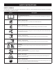
SAFETY INSTRUCTIONS Safety Symbols This page depicts and describes safety symbols that may appear on this product. Read, understand, and follow all instructions on the machine before attempting to assemble and operate. Symbol Description READ THE OPERATOR’S MANUAL(S) Read, understand, and follow all instructions in the manual(s) before attempting to assemble and operate DANGER— ROTATING BLADES Never carry passengers. Never carry children, even with the blades off.
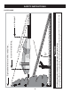
d line dotte ing a (repr esent lope) 15° s or a fence post Do not operate your lawn mower on such slopes. Do not mow on inclines with a slope in excess of 15 degrees (a rise of approximately 2-1/2 feet every 10 feet). A riding mower could overturn and cause serious injury. Operate riding mowers up and down slopes, never across the face of slopes. Use this page as a guide to determine slopes where you may not operate safely. WARNING 15° long Fold a or a corner of a building...
SAFETY LABELS WARNING This symbol points out important safety instructions which, if not followed, could endanger the personal safety and/or property of yourself and others. Read and follow all instructions in this manual before attempting to operate this machine. Failure to comply with these instructions may result in personal injury.
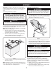
ASSEMBLY Shipping Brace Removal IMPORTANT: Your tractor is shipped with motor oil in the engine. However, you MUST check the oil level before operating. Refer to the Service & Maintenance section for instructions on checking the oil level. WARNING Make sure the riding mower’s engine is off, remove the ignition key, and set the parking brake before removing the shipping brace. Refer to the Operation section for instructions on how to set the parking brake.
ASSEMBLY Adjusting the Seat To adjust the position of the seat, pull up and hold the seat adjustment lever. Slide the seat forward or rearward to the desired position; then release the adjustment lever. Make sure seat is locked into position in a seat-stop before operating the tractor. See Figure 5. WARNING Before operating the tractor, make sure the seat is engaged in a seat-stop. Engage the parking brake. Stand behind the machine and pull back on seat until it clicks into place. 3.
OPERATION B A C J D E I H F G Figure 6 A Parking Brake Lever F PTO Lever (Blade Engage) B Throttle/Choke Control Lever G Cup Holder C Ignition Switch Module H Shift Lever D Auto-drive Pedal I Seat Adjustment Lever E Deck Lift Lever J Brake Pedal NOTE: Any reference in this manual to the RIGHT or LEFT side of the tractor is observed from operator’s seat position facing forward towards the front of tractor.
OPERATION Parking Brake Lever Auto-drive pedal To set the parking brake: Fully depress the brake pedal. Move the parking brake lever into the parking brake position. Release the brake pedal to allow the parking brake to engage. To release the parking brake: Depress the brake pedal and the parking brake lever will move out of the parking brake position on its own. The parking brake will then be released. Release the brake pedal.
OPERATION Gas and Oil Fill-up Oil IMPORTANT: Your tractor is shipped with motor oil in the engine. However, you MUST check the oil level before operating. Be careful not to overfill. For instructions on how to check the engine oil, refer to Checking The Engine Oil in the Service and Maintenance section of this manual. Gasoline The gasoline tank is located under the hood. Do not overfill. WARNING Use extreme care when handling gasoline. Gasoline is extremely flammable and the vapors are explosive.
OPERATION Safety Interlock System Setting the Cutting Height The safety interlock system is designed for safe operation of the tractor. If this system should ever malfunction, do not operate the tractor, Immediately contact 1-800-4-MY-HOME to have the system serviced. • The safety interlock system prevents the engine from starting unless the parking brake is engaged and the PTO (Blade Engage) lever is in the disengaged (OFF) position.
OPERATION 5. Turn the ignition key clockwise to the START position. After the engine starts, release the key. It will return to the ON (or Normal Mowing) position. Driving The Tractor WARNING Avoid sudden starts, excessive speed and sudden stops. CAUTION WARNING Do NOT hold the key in the START position for longer than ten seconds at a time. Doing so may cause damage to your engine’s electric starter. 6.
OPERATION Driving On Slopes Mowing Refer to the SLOPE GAUGE in the Safety Instructions section of the manual to help determine slopes where you may operate this tractor safely. WARNING To help avoid blade contact or a thrown object injury, keep bystanders, helpers, children and pets at least 75 feet from the machine while it is in operation. Stop machine if anyone enters the area. WARNING Do not mow on inclines with a slope in excess of 15 degrees (a rise of approximately 2-1/2 feet every 10 feet).
SERVICE AND MAINTENANCE MAINTENANCE SCHEDULE WARNING Before performing any type of maintenance/service, disengage all controls and stop the engine. Wait until all moving parts have come to a complete stop. Disconnect spark plug wire and ground it against the engine to prevent unintended starting. Always wear safety glasses during operation or while performing any adjustments or repairs. Interval Follow the maintenance schedule given below. This chart describes service guidelines only.
SERVICE AND MAINTENANCE Engine Maintenance Changing Engine Oil Checking the Engine Oil The engine oil should be changed in the first 5 hours and then every 50 hours or once a season. To change the engine oil, proceed as follows: 1. With engine OFF but still warm, disconnect spark plug wire and keep it away from spark plug. 2. Remove the oil fill cap/dipstick from the oil fill tube. See Figure 9. 3. Turn the steering wheel all the way to the right to better expose the drain plug. 4.
SERVICE AND MAINTENANCE Air Cleaner mark on the dipstick. Fuel Filter WARNING WARNING If filters, or covers are not installed correctly serious injury or death could result from backfire. Do not attempt to start the engine with them removed. Gasoline and its vapors are extremely flammable and explosive. Fire or explosion can cause severe burns or death. Keep gasoline away from sparks, open flames, pilot lights, heat, and other ignition sources.
SERVICE AND MAINTENANCE Lubrication Spark Plug 1. 2. Clean area around the spark plug base. Do not sandblast spark plug. Spark plug should be cleaned by scraping or wire brushing and washing with a commercial solvent Remove and inspect the spark plug. Check gap to make sure it is set at .030”. See Figure 13.
SERVICE AND MAINTENANCE Cleaning the Engine And Deck 2. Any fuel or oil spilled on the machine should be wiped off promptly. Do NOT allow debris to accumulate around the cooling fins of the engine or on any other part of the machine. IMPORTANT: The use of a pressure washer to clean your tractor is NOT recommended. It may cause damage to electrical components, spindles, pulleys, bearings or the engine. A screw plug can be found on your tractor’s deck surface as seen in Fig. 14.
SERVICE AND MAINTENANCE A C B Hex Cap Screw Seat Adjustment Figure 16 5. Refer to the Assembly section of this manual for seat adjustment instructions. Parking Brake Adjustment Figure 17 Looking at the cutting deck from the left side of the tractor, locate the bow-tie pin that secures the deck support rod on the rear left side of the deck. See Fig. 18. Remove the bow-tie pin that secures the deck support rod, and carefully remove the deck support from the deck lift arm.
SERVICE AND MAINTENANCE 8. Remove the bow-tie cotter pin securing the deck stabilizer rod to the deck. Slide the deck lift rod from the mounting bracket on the deck as seen in Fig. 19. The recommended operating tire pressure is: • • Approximately 10 psi for the rear tires Approximately 14 psi for the front tires IMPORTANT: Refer to the tire sidewall for exact tire manufacturer’s recommended or maximum psi. Do not overinflate. Uneven tire pressure could cause the cutting deck to mow unevenly.
SERVICE AND MAINTENANCE If your tractor has not been put into use for an extended period of time, charge the battery as follows: 1. Set your battery charger to deliver a max of 10 amperes. If your battery charger is automatic, charge the battery until the charger indicates that charging is complete. If the charger is not automatic, charge for no fewer than eight hours. 3. 4. Fuse Remove the hex flange nut that secures the blade to the spindle assembly. See Fig. 21.
SERVICE AND MAINTENANCE IMPORTANT: The V-belt found on your tractor is specially designed to engage and disengage safely. A substitute (non-OEM) V-belt can be dangerous by not disengaging completely. For a proper working machine, use identical equipment belts as listed in the parts pages of this Operator’s Manual. To change or replace the deck belt on your tractor, proceed as follows: 1. Remove the deck as instructed earlier in this section. 2.
OFF-SEASON STORAGE WARNING Never store lawn tractor with fuel in tank indoors or in poorly ventilated areas where fuel fumes may reach an open flame, spark, or pilot light as on a furnace, water heater, clothes dryer, or gas appliance. Preparing THE Engine IMPORTANT: Fuel left in the fuel tank during warm weather deteriorates and will cause serious starting problems.
TROUBLESHOOTING Problem Engine fails to start Cause 5. PTO/Blade Engage lever engaged. Parking brake not engaged. Spark plug wire(s) disconnected. Throttle/Choke control lever not in correct starting position. Choke not activated 6. 7. 8. 9. 10. Fuel tank empty, or stale fuel. Blocked fuel line. Faulty spark plug(s). Engine flooded. Blown Fuse(s) Move the Throttle/Choke lever into the Choke position. 6. Fill tank with clean, fresh (less than 30 days old) gas. 7.
Labels 777D15653 777X43688 DO NOT 777S33818 E VO • DO NOT OPERATE THE UNIT WHERE IT COULD SLIP OR TIP. • IF MACHINE STOPS GOING UPHILL, STOP BLADE(S) AND BACK DOWNHILL SLOWLY. AG TO AVOID SERIOUS INJURY OR DEATH • GO UP AND DOWN SLOPES, NOT ACROSS. • AVOID SUDDEN TURNS. A DANGER ROTATING BLADES CAUSE SERIOUS INJURY OR DEAT H TO 4. TURN KEY TO START ENGINE. AFTER START RELEASE KEY AND DEACTIVATE CHOKE BY PLACING THROTTLE TO FAST “RABBIT” POSITION.
PARTS LIST Craftsman Model 247.
PARTS LIST Craftsman Model 247.28884 Ref. No. 1 Part No. 925-1649 Ref. No. Description Part No. Description Bulb Socket 25 712-04065 Nut, Hex Flange Insert Lock, 3/8-16 714-04040 Cotter Pin 2 683-04619-4043 Hood Assembly 26 3 710-04484 Screw, 5/16-18 x .750 27 783-06823 Speed Latch Support Tab 4 710-0599 Hex Washer Screw, 1/4-20 x .
PARTS LIST Craftsman Model 247.
PARTS LIST Craftsman Model 247.28884 Ref. No. 1 Part No. 683-04155A-0637 Ref. No. Description Part No. Description Shaft, Lift 24 756-04196A Engagement Pulley 747-04857 Belt Keeper Rod Assembly 710-04484 Screw, Hd. Tapp, 5/16-18 x .75 2 712-04065 Nut, Hex Flange Insert Lock, 3/8-16 25 3 714-04040 Bow-Tie Pin, 91, RH 26 4 716-0106A E-ring, .625 Shaft 27 683-04195-0637 Support Bracket Assembly 683-04601-0637 Rider Frame Assembly 710-0134 Carriage Screw, 1/4-20 x .
PARTS LIST Craftsman Model 247.
PARTS LIST Craftsman Model 247.28884 Ref. No. Part No. Ref. No. Description Part No. Description 1 617-04094 Gear Assembly, Steering 21 683-0128B-0637 Pivot Bar Axle Assembly 2 710-0643 Screw, 5/16-18, 1.00, Gr5, Lock 22 710-04484 Screw, 5/16-18, 0.750 3 710-1309 Screw, Mach, 5/16-18, 0.750 23 712-04065 Nut, Flange Lock, 3/8-16, GrF 4 710-3094A Hex Head Screw, 3/8-16 x 1.00 24 714-04039A Pin, Cotter, 5/32, 1.25 5 710-3180 Screw, 5/16-18, 1.
PARTS LIST Craftsman Model 247.
PARTS LIST Craftsman Model 247.28884 Ref. No. Part No. Description 1 710-04482 Hex Flange Bolt, 3/8-16 x .875 2 710-04484 Screw, Hd. Tapp, 5/16-18 x .75 3 712-3004A Flange Lock Nut, 5/16-18 4 725-05013 Seat Safety Switch 5 725-05277 Seat Jumper Harness (not shown) 6 726-0154 Push Mount Cable Tie 7 732-04035 Spring, Compress., 1.28 x 3.125 8 732-04563 Spring, Compress., .68 x 1.065 x .055 9 938-0296 Shoulder Screw, 5/16-18 x .437 x .
PARTS LIST Craftsman Model 247.
PARTS LIST Craftsman Model 247.28884 Ref. Part No. Description 1 683-04549-0637 Muffler Shield Assembly 2 710-0227 Screw, AB #8-18 0.500 3 710-04683 Tap Screw, 3/8-16 1.000 4 710-0642 Tap Screw, 1/4-20 0.750 5 710-1314A Screw, Socket Head, 5/16-18 x .750 6 712-0271 Sems Nut, 1/4-20 7 BS-692236 Exhaust Gasket 8 725-0157 Cable Tie, 3/16 X .05 X 7.4 9 726-0205 Hose Clamp, .490 Dia.
PARTS LIST Craftsman Model 247.
PARTS LIST Craftsman Model 247.28884 Ref. 1 Part No. 918-04566 Description Ref. 45 Dr Assembly, Autodrive Lt-5 Part No. 731-04604 Description Sleeve, .758 X .821 X 2.4375 2 683-04606 Auto-drive Bracket Assembly 46 731-06330 Plug, Deck Hole, 7/8 3 683-04684 Idler Bracket Assembly 47 731-06894 Shift Plate Bearing 4 710-1260A Tap Screw, 5/16-18 x 0.750 48 732-04488 Spring, Ext, .38 Od X 3.25 Lg 5 712-04065 Flange Lock Nut, 3/8-16 49 732-04612 Spring, Extn, .70 Dia X 12.
PARTS LIST Craftsman Model 247.
PARTS LIST Craftsman Model 247.28884 Ref. No. Part No. Ref. No. Description Part No. Description 1 918-04822A Spindle Pulley Assembly 30 736-0362 Flat Washer, .330 x 1.25 x .06 2 683-0254B-0637 Deck Hanger Bracket Assembly 31 738-04146 Bolt Plug, M16 x 1.5 3 936-0344 Wash, Flat, .385 x 1.0 x .030 32 738-04162A Shoulder Spacer, .8840 x .190 4 983-04511 Brake Assembly 33 938-3056 Shoulder Bolt, 3/8-16 5 983-04525 Brake Assembly 34 942-04308 Cutting Blade, 21.
PARTS LIST Craftsman Engine Model 31P677-3373-G2/G6 For Model 247.28884 1058 OPERATOR’S MANUAL 48 SHORT BLOCK 29 1329 REPLACEMENT ENGINE 1330 REPAIR MANUAL 11 32 684 1 2 3 28 850 584 585 27 1264 25 27 1263 552 691 718 16 26 1044 24 306 146 307 46 741 616 43 45 227 758 404 614 505 1270 757 759 847 562 4 523 12 842 1017 1024 525 15 22 1027 20 524 965 943 750 Assemblies include all parts shown in frames.
PARTS LIST Craftsman Engine Model 31P677-3373-G2/G6 For Model 247.28884 5 34 33 868 42 42 45 238 306 36 1026 35 7 1026A 13 1022 1034 337 1029 635 830 192 51 617 1023 51A 883 1022 50 51 617 914 51A 415 850 186 54 654 53 Assemblies include all parts shown in frames.
PARTS LIST Craftsman Engine Model 31P677-3373-G2/G6 For Model 247.28884 125 141 131 108 634 130 633 95 987 217 98 94 51 105 118 117 133 1091 127 104 654 135A 53 137 975 137 135 947 137 276 1127 431 187 240 964 601 1266 Assemblies include all parts shown in frames.
PARTS LIST Craftsman Engine Model 31P677-3373-G2/G6 For Model 247.28884 1036 EMISSIONS LABEL 1040 304 305 445 305A 968 305B 324 415 1070 1005 1044 23 78 1051 37 783 Assemblies include all parts shown in frames.
PARTS LIST Craftsman Engine Model 31P677-3373-G2/G6 For Model 247.28884 334 474 333 1059 851 635 1119 309 510 1051 1054 801 783 789 310 513 877 729 1090 503 462 579 797 802 697 188 216 222 209 202 265 232 267 Assemblies include all parts shown in frames.
PARTS LIST Craftsman Engine Model 31P677-3373-G2/G6 For Model 247.28884 121 CARBURETOR OVERHAUL KIT 51 127 987 617 1266 137 104 634 633 105 217 1266A 850 358 ENGINE GASKET SET 3 883 12 943 7 20 691 51 9 1022 842 524 1266 868 617 1095 VALVE GASKET SET 51 7 1022 868 Assemblies include all parts shown in frames.
PARTS LIST Craftsman Engine Model 31P677-3373-G2/G6 For Model 247.28884 Ref. No. Part No. 1 796010 2 3 Ref. No. Part No.
PARTS LIST Craftsman Engine Model 31P677-3373-G2/G6 For Model 247.28884 Ref. No. Part No. 306 796006 307 Ref. No. Part No.
PARTS LIST Craftsman Engine Model 31P677-3373-G2/G6 For Model 247.28884 Ref. No. Part No.
Notes Page This page intentionally left blank. Use this page to make any notes regarding your tractor.
Look For Relevant Emissions Durability Period and Air Index Information On Your Engine Emissions Label Engines that are certified to meet the California Air Resources Board (CARB) Tier 2 Emission Standards must display information regarding the Emissions Durability Period and the Air Index. Sears Brands Management Corporation makes this information available to the consumer on our emission labels.
(This page applicable in the U.S.A. and Canada only.) Sears Brands Management Corporation (Sears), the California Air Resources Board (CARB) and the United States Environmental Protection Agency (U.S.
FEDERAL and/or CALIFORNIA EMISSION CONTROL WARRANTY STATEMENT YOUR WARRANTY RIGHTS AND OBLIGATIONS MTD Consumer Group Inc, the United States Environmental Protection Agency (EPA), and, for those products certified for sale in the state of California, the California Air Resources Board (CARB) are pleased to explain the emission (evaporative and/or exhaust) control system (ECS) warranty on your outdoor 2006 and later small off-road spark-ignited engine and equipment (outdoor equipment engine) In California, n
WARRANTED PARTS: The repair or replacement of any warranted part otherwise eligible for warranty coverage may be excluded from such warranty coverage if MTD Consumer Group Inc demonstrates that the outdoor equipment engine has been abused, neglected, or improperly maintained, and that such abuse, neglect, or improper maintenance was the direct cause of the need for repair or replacement of the part.
REPAIR PROTECTION AGREEMENT Congratulations on making a smart purchase. Your new Craftsman® product is designed and manufactured for years of dependable operation. But like all products, it may require repair from time to time. That’s when having a Repair Protection Agreement can save you money and aggravation.
ÍNDICE Operación segura Prácticas . . . . . . . . . . Páginas 59 Etiquetas De Seguridad . . . . . . . . . . . . . . . . . Page 65 Asamblea . . . . . . . . . . . . . . . . . . . . . . . . . . . . Page 66 Operación de . . . . . . . . . . . . . . . . . . . . . . Páginas 68 De Servicio y Mantenimiento de . . . . . . . Páginas 75 Fuera de temporada de almacenamiento . . . Page 85 Solución de problemas . . . . . . . . . . . . . . . . . Page 86 Lista de piezas . . . . . . . . . . . . . . . . . . . . .
INSTRUCCIONES DE SEGURIDAD ADVERTENCIA PELIGRO La presencia de este símbolo indica que se trata de instrucciones importantes de seguridad que se deben respetar para evitar poner en peligro su seguridad personal y/o material y la de otras personas. Lea y siga todas las instrucciones de este manual antes de poner en funcionamiento esta máquina. Si no respeta estas instrucciones podría provocar lesiones personales.
INSTRUCCIONES DE SEGURIDAD • • • • • • • • • Nunca deje la máquina en funcionamiento sin vigilancia. Apague siempre las cuchillas, coloque el freno de mano, detenga el motor y retire la llave antes de bajarse del vehículo. Tenga sumo cuidado al cargar o descargar la máquina en un remolque o camión. Esta unidad no debe conducirse en ascenso o descenso de rampas, porque podría ladearse y provocar lesiones personales graves.
INSTRUCCIONES DE SEGURIDAD • Para evitar accidentes al operar en marcha atrás, siempre desenganche las cuchillas antes de colocar marcha atrás. Si está instalado, el “Modo Precaución Marcha Atrás” (hojas de operar la máquina, mientras que los paseos a la inversa) no debe utilizarse cuando hay niños u otras personas presentes. • Mantenga a los niños alejados de los motores en marcha o calientes. Pueden sufrir quemaduras con un silenciador caliente.
INSTRUCCIONES DE SEGURIDAD • • • • • • • • • • • Revise los pernos de montaje de la(s) cuchilla(s) y del motor a intervalos frecuentes para verificar que estén bien apretados. Además, inspeccione visualmente la(s) cuchilla(s) en busca de daños (por ejemplo, desgaste excesivo, abolladuras, rajaduras, etc.). Reemplace la(s) cuchilla(s) únicamente con las cuchillas de fabricantes de equipos originales (O.E.M.) listadas en este manual.
INSTRUCCIONES DE SEGURIDAD Símbolos De Seguridad Esta página representa y describe la seguridad los símbolos que pueden parecer en este producto. Lea, comprenda, y siga todas instrucciones en la máquina antes procurar para reunir y operar. Symbol Description LEA EL MANUAL(S) DEL OPERADOR leído, entienda, y siga todas las instrucciones en el manual(s) antes de procurar montar y funcionar PELIGRO— DÉ EL CORTE DE PIE Nunca transporte pasajeros. Nunca transporte niños, aún con la cuchilla apagada.
INSTRUCCIONES DE SEGURIDAD Guía de pendiente Mire y mantenga este nivel con un árbol vertical Doble 15° por o la esquina de un edificio... °) pend i e n t e de 15 o el poste de una empalizada s (rep r e s e n ta una la líne a d e p unto ADVERTENCIA Use esta página como guía para determinar en qué pendientes no puede operar el tractor de manera segura. No opere la cortadora de césped en dichas pendientes.
ETIQUETAS DE SEGURIDAD ADVERTENCIA Este símbolo señala a cabo las instrucciones de seguridad importantes que, si no se siguen, podría poner en peligro la seguridad personal y / o la propiedad de sí mismo y los demás. Lea y siga las instrucciones en este manual antes de intentar operar esta máquina. El incumplimiento de estas instrucciones puede resultar en lesiones personales.
ASAMBLEA Envío Brace eliminación IMPORTANTE: Su tractor se entrega con aceite de motor en el motor. Sin embargo, debe comprobar el nivel de aceite antes de operar. Consulte la sección de Servicio y Mantenimiento para obtener instrucciones sobre la comprobación del nivel de aceite. ADVERTENCIA Asegúrese de que el motor del tractor cortacésped es, retire la llave de encendido, y poner el freno antes de quitar la llave de envío.
ASAMBLEA 2. Coloque la arandela (con la parte ahuecada hacia abajo) sobre el volante y segura con el tornillo hexagonal. Véase la figura. 3. 3. Conecte el mazo de cables en el interruptor de seguridad del asiento en la parte inferior del asiento, como se muestra en B de la Figura 4. NOTA: El tractor no funciona con el cable de alimentación desconectado. Ajuste del asiento Para ajustar la posición del asiento, tírelo hacia arriba y sostenga la palanca de ajuste del asiento.
OPERACIÓN B A C D J E I H G F Figure 6 NOTA: Cualquier referencia hecha en este manual al lado DERECHO o IZQUIERDO del tractor debe entenderse tal como se observa desde la posición del operador. Cumple con los estándares de seguridad de ANSI Las máquinas quitanieve de Craftsman cumplen con los estándares de seguridad del instituto estadounidense de estándares nacionales (ANSI).
OPERACIÓN Levante la palanca de la cubierta Para ajustar el freno de estacionamiento: completamente el pedal de freno. Mover la palanca del freno de estacionamiento en la posición del freno de estacionamiento. Suelte el pedal del freno para que el freno de estacionamiento a participar. Para liberar el freno de estacionamiento: Presione el pedal de freno y la palanca del freno de estacionamiento se moverá de la posición del freno de estacionamiento por su propia cuenta.
OPERACIÓN Embrague-pedal de freno El embrague-pedal del freno está situado en el lado izquierdo del tractor de césped, a lo largo del estribo. Pisar el embrague-pedal de freno para la participación del disco de freno y llevar el tractor a una parada completa. NOTA: El pedal debe ser presionada para encender el motor. Consulte Interruptores de enclavamiento de seguridad más adelante en esta sección de este manual.
OPERACIÓN ADVERTENCIA Evite lesiones personales graves o la muerte • En las pendientes conduzca hacia arriba y hacia abajo, no de forma transversal. • Evite maniobras de giro bruscas. • No opere la unidad en áreas donde puede derrapar o ladearse. • Si la máquina deja de subir la pediente detenga las cuchillas y retroceda lentamente bajando la pendiente. • No corte el césped cuando haya niños u otras personas cerca. • Nunca transporte niños, ni siquiera si las cuchillas están desconectadas.
OPERACIÓN Paro del motor ADVERTENCIA Si se golpea un objeto extraño, detenga el motor, desconecte el cable de la bujía (s) y tierra contra el motor. Inspeccionar cuidadosamente el equipo de los daños. Reparación de los daños antes de reiniciar y de funcionamiento. 1. 2. 3. Si se dedican a las hojas, colocar la toma de fuerza (Blade Engage) palanca en la posición OFF desconectado posición. Gire a la izquierda la llave de encendido a la posición STOP.
OPERACIÓN Conducción en las laderas Involucrar a los Blades Refieren al ancho de la pendiente en la seguridad de las prácticas de operación importante sección del manual para ayudar a determinar zonas de ladera donde puede operar el tractor con total seguridad. Participación de la toma de fuerza (Blade Engage) las transferencias de energía a la plataforma de corte o de otro tipo (disponible por separado) los archivos adjuntos. Para participar de las hojas, haga lo siguiente: 1.
OPERACIÓN Cortar Faros ADVERTENCIA Para ayudar a evitar el contacto con la cuchilla o una lesión en el objeto lanzado, Mantenga a los espectadores, los ayudantes, los niños y las mascotas por lo menos 75 pies de distancia de la máquina mientras está en funcionamiento. Parada de la máquina, si alguien entra en el área.
SERVICIO Y MANTENIMIENTO LISTA DE MANTENIMIENTO ADVERTENCIA Antes de realizar cualquier tipo del mantenimiento/servicio, suelte todos los mandos y pare el motor. Espere hasta que todas las partes de movimiento hayan venido a una parada completa. Desconecte el alambre de bujía y báselo contra el motor para prevenir el comienzo involuntario. Siempre lleve puestos cristales inastillables durante la operación o realizando cualquier ajuste o reparaciones. Intervalo Siga la lista de mantenimiento dada abajo.
SERVICIO Y MANTENIMIENTO Mantenimiento del motor PRECAUCIÓN Comprobar el aceite del motor No llene demasiado. Llenado excesivo de aceite puede provocar que el motor no empezar, difícil de partida, o fumar motor. Si más de la marca FULL en la varilla, el aceite de drenaje para reducir el nivel de aceite en FULL marca en la varilla de medición. Sólo el uso de aceite de alta detergente se evaluó la calidad con la clasificación de servicio API SF, SG, SH, o SJ.
SERVICIO Y MANTENIMIENTO Fuel Filter • Mantenga la gasolina lejos de chispas, llamas, luces piloto, el calor, y otras fuentes de ignición. • Compruebe las líneas de combustible, el tanque, la tapa y los accesorios con frecuencia para detectar rajaduras o escapes. Reemplazar si es necesario. • Antes de reemplazar el filtro de combustible, vaciar el tanque de combustible según las instrucciones de abajo. • No fuga de combustible cuando el motor está caliente.
SERVICIO Y MANTENIMIENTO Bujía Puntos de pivote y Vinculación 1. Lubricar todos los puntos de giro en el sistema de tracción, freno de estacionamiento y la vinculación levantar al menos una vez al año con aceite de la luz. 2. Limpie el área alrededor de la base de la bujía. No chorro de arena de la bujía. La bujía debe limpiarse por raspado o cepillo de alambre y el lavado con un disolvente comercial de Retirar e inspeccionar la bujía. Brecha Asegúrese de que se ha fijado en .030 “. Ver Figura 15.
SERVICIO Y MANTENIMIENTO Limpieza de las máquinas y la cubierta Cualquier combustible o aceite derramado en la máquina debe ser borrado de inmediato. NO permita que los desechos que se acumulan alrededor de las aletas de refrigeración del motor o en cualquier otra parte de la máquina. IMPORTANTE: El uso de una lavadora de presión para limpiar su tractor no se recomienda. Puede causar daños a los componentes eléctricos, ejes, poleas, rodamientos o el motor.
SERVICIO Y MANTENIMIENTO 2. 3. Bajo la cubierta moviendo la palanca de elevación de cubierta en la muesca en la parte inferior del guardabarros derecho. Extracción de la auto-Tornillo (A) que asegura el cinturón-Rod de todo poseedor de la polea del motor del tractor, a continuación, quitar la varilla poseedor del cinturón (B). Véase la figura. 11. Nota: Haga una nota mental de lo agujero al otro extremo de la cinta-Rod poseedor se inserta en los propósitos de reinstalación. 4.
SERVICIO Y MANTENIMIENTO 6. Neumáticos figura. 20. Retire el arco alfiler de corbata que asegura la vara de apoyo de cubierta, y retirar con cuidado el apoyo de la cubierta de los brazos de elevación de la cubierta. Repita los pasos anteriores en el lado derecho del tractor. ADVERTENCIA No sobrepasar nunca la presión máxima de inflado que aparece en la pared lateral de la llanta. NOTA: El arco de pelo alfiler de corbata clips debe ser instalado desde arriba hacia abajo. 7.
SERVICIO Y MANTENIMIENTO Carga ADVERTENCIA Baterías emiten un gas explosivo durante la carga. Carga de la batería en un área bien ventilada y mantenerse lejos de una llama abierta o piloto como en un calentador de agua, estufa, horno, secadora de ropa o de otros aparatos de gas. PRECAUCIÓN Al cargar la batería de su tractor, utilice sólo un cargador de 12V diseñado para baterías de plomo-ácido. Lea su cargador de batería manual del propietario antes de cargar la batería de su tractor.
SERVICIO Y MANTENIMIENTO NOTA: Cuando tenga que reemplazar la hoja, asegúrese de instalar la hoja con la cara de la hoja marcada’’fondo’’(o con un número estampado en él) frente a la tierra cuando el cortacésped se encuentra en la posición de funcionamiento. PRECAUCIÓN Utilice una llave de par para apretar la tuerca de husillo de la hoja brida hexagonal a entre 70 libras-pie y 90 libras-pie.
ALMACENAMIENTO FUERA DE TEMPORADA ADVERTENCIA Nunca almacene tractor de césped con combustible en el tanque en un espacio cerrado o en áreas con poca ventilación, donde los gases del combustible puedan alcanzar el fuego, chispas o una luz piloto como la que tienen algunos hornos, calentadores de agua, secadores de ropa o algún otro dispositivo a gas. El drenaje de los combustibles Preparación del motor 1.
SOLUCIÓN DE PROBLEMAS Problema Causa Remedio El motor no arranca 1. 2. 3. 4. Perilla de potencia de arranque (PTO)conectada. No está colocado el freno de mano. Se ha desconectado el cable de las bujías. La palanca de control del regulador no está en la posición de arranque correcta. 5. No se ha activado el cebador 6. El depósito de combustible está vacío o el combustible se ha echado a perder. 7. La línea del combustible está bloqueada. 8. Las bujías no funcionan correctamente. 9. Motor ahogado. 10.
Busque el período de duración de emisiones importantes yla información de clasificación de aire en la etiqueta de emisiones de su motor Los motores cuyo cumplimiento con los estándares de emisión Tier 2 de la Comisión de Recursos Ambientales de California (CARB) esté certificado deben exhibir la información relacionada con el período de duración de las emisiones y la clasificación de aire.
(Esta página se aplica sólo en EE.UU. y Canadá).
DECLARACIÓN FEDERAL y/o DE CALIFORNIA SOBRE GARANTÍAS EN EL CONTROL DE EMISIONES SUS DERECHOS Y OBLIGACIONES EN CUANTO A LA GARANTÍA MTD Consumer Group Inc, la Agencia de Protección Medioambiental de los Estados Unidos (EPA), y para aquellos productos certificados para su venta en el estado de California, el Departamento de los Recursos del Aire de California (CARB) se complacen en explicar la garantía que cubre al sistema de control (ECS) de emisiones (evaporativas y/o de escape) de su equipo y motor (moto
8. Durante la totalidad del período de garantía del motor y equipo para todo terreno arriba mencionado, MTD Consumer Group Inc mantendrá un suministro de piezas bajo garantía suficiente para satisfacer la demanda esperada de tales piezas. 9. Cualquier pieza de reemplazo se podrá usar para el cumplimiento del mantenimiento o las reparaciones bajo garantía y se suministrarán sin cargo para el propietario. Dicho uso no reducirá las obligaciones de garantía de MTD Consumer Group Inc. 10.
ACUERDO DE PROTECCIÓN PARA REPARACIONES Felicitaciones por haber realizado una adquisición inteligente. El producto Craftsman® que ha adquirido está diseñado y fabricado para brindar muchos años de funcionamiento confiable. Pero como todos los productos a veces puede requerir de reparaciones. Es en ese momento cuando el disponer de un Acuerdo de protección para reparaciones le puede ahorrar dinero y problemas.
Riding Equipment questions or problems? Satisfaction with your purchase is our number one concern! To troubleshoot problems, get answers to questions, order parts, or schedule repair service for your Riding Equipment, call the number below. Para respuestas a preguntas o problemas, y ordenar piezas o pedir servicio para la reparación de su equipo, llame el número abajo. 1-800-659-5917 Craftsman Help Line www.craftsman.