
Operator`s manual


5. Pullstarterropehandlesharplyuntil
engineruns.
6. Oncetheenginestarts,allowitto
runamaximumof10secondsat
FULLCHOKE.Then,slowlymove
theredchokelevertotheHALF
CHOKEposition.
7. Allowtheunittorunaminimumof
20moresecondsatHALFCHOKE
(coldertemperaturesmayrequire
longerwarm-upperiodsbefore
theenginewillacceptaloadand
accelerateproperly).
8. MoveredchokelevertoOFF
CHOKEpositionandallowtheunitto
runaminimumof20moreseconds
atOFFCHOKE.Releasethethrottle
trigger.
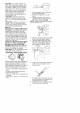
STARTING ENGINE
NOTE: Check oil level before starting.
Oil level should be at the FULL mark
on the dipstick. If not, add oil (see
ADD OIL section).
1. Set unit on a flat surface.
2. Slowly press the primer bulb 8
times.
3. Move red choke lever to FULL
CHOKE position.
4. Squeeze the throttle trigger fully and
hold through all remaining steps.
5. Pull starter rope handle sharply until
engine runs.
6. Once the engine starts, allow it to
run a maximum of 10 seconds at
FULL CHOKE. Then, slowly move
the red choke lever to the HALF
CHOKE position.
7. Allow the unit to run a minimum of
20 more seconds at HALF CHOKE
(colder temperatures may require
longer warm-up periods before
the engine will accept a load and
accelerate properly).
8. Move red choke lever to OFF
CHOKE position and allow the unit to
run a minimum of 20 more seconds
at OFF CHOKE. Release the throttle
trigger.
RESTARTING A WARM ENGINE
Follow steps listed in the STARTING
ENGINE section without squeezing
throttle trigger.
If the unit will not start, refer to the
TROUBLESHOOTING TABLE or call
1-800-235-5878.
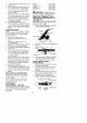
CRAFTSMAN ®
CONVERTIBLE TM FEATURE
This model is equipped with a coupler
which enables optional attachments to
be installed. The optional attach-
ments are:
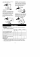
Edger ............... 358.79240
Cultivator ............ 358.79241
Blower .............. 358.79242
Brushcutter .......... 358.79244
Pruner .............. 358=79245
_&WARNING: Always stop unit
and disconnect spark plug before re-
moving or installing attachments.
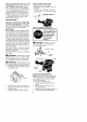
REMOVING TRIMMER ATTACH-
MENT (OR OTHER OPTIONAL AT-
TACHMENTS)
CAUTION: When removing or instal-
ling attachments, place the unit on a
flat surface for stability.
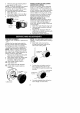
1. Loosen the coupler by turning the
knob counterclockwise.
Upper Shaft
Coupler
Attachment
TIGHTEN Knob
2. Press and hold the locking/release
button.
Locking/Release
Button
/ cup er_== Upper Shaft
Attachment
3. While securely holding the engine
and upper shaft, pull the attach-
ment straight out of the coupler=
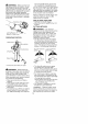
INSTALLING OPTIONAL
ATTACHMENTS
1. Remove the shaft cap from the at-
tachment (if present).
2. Position locking/release button of
attachment into guide recess of
coupler.
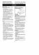
3. Push the attachment into the cou-
pler until the locking/release button
snaps into the primary hole.
4. Before using the unit, tighten the
knob securely by turning clockwise=
Coupler Primary Hole
Guide Recess
13
Upper Locking/
Shaft Release
Button
Attachment