IMPORTANT MANUAL Do Not Throw Away Operator's Manual Model No. 358.797922-32cc 358.797950-22cc 358.797982-32cc 358.797961-22cc 358.797990-32cc Always Wear Eye Protection . CRAFTSMAN® Hours (CST) Mon + Sat 7 a.m+- 7 p.m. Sun !0 a.m. - 7 p.m. _ READ THE OPERATOR'S DANGER MANUAL AND FOLLOW ALL WARNINGS AND SAFETY INSTRUCTIONS. FAILURE TO DO SO CAN RESULT IN "SERIOUS INJURY.
i SAFETY RULES CAUTION: ALWAYS DISCONNECT SPARK PLUG WIRE AND PLACE WIRE WHERE tT CANNOT I CONTACT SPARK PLUG TO PREVENT ACCIDENTAL STARTING WHEN SETTING UP.t TRANSPORTING, ADJUSTING OR MAKING REPAIRS. 1 OPERATOR SAFETY • Always wear eye protection to prevent rocks or debris from being blown or ricocheting into eyes and face which can result in blindness and!or other serious injury. • Always wear a respirator or facemask when working with the unit in dusty' environments.
SAFETY RULES WARNING THIS POWER UNIT CAN BE DANGEROUS! THIS UNIT CAN CAUSE SERIOUS INJURY OR BLINDNESS TO THE OPERATOR AND OTHERS. THE WARNINGS AND SAFETY INSTRUCTIONS IN THIS MANUAL MUST BE FOLLOWED TO PROVIDE REASONABLE SAFETY AND EFFICIENCY IN USING THIS UNIT. THE OPERATOR IS RESPONSIBLE FOR FOLLOWING THE WARNINGS AND INSTRUCTIONS IN THIS MANUAL AND ON THE UNIT.
CONGRATULATIONS on yourpurchaseof a Sears Craftsman Gasoline Blower.It hasbeendesigned, engineeredandmanufactured to giveyouthebestpossible dependability andperformance. Should you experience any problems you cannot easily remedy, please contact your nearest Sears Service Center/Department or Call the 1-800 number listed on the front of this manual. Sears has competent, well trained technicians and the proper tools to service or repair this unit.
HARDWARE _._ I.... i illiiiiii ii iiiiii iiii .......... i II II II IIIIII IIIIII I II I CONTENTS I nil lli I Illll IIIIIIIIIIllLl IIJlll I 7 IIIII iiii I Parts packed separately in carton VACUUM BAG 358.797982, 358.797950 & 358.797990 OPERATOR'S MANUAL UPPER VACUUM TUBE 358.797982, 358.797950 & 358.797990 LOWER VACUUM TUBE 358.797982, 358.797950 & 358.797990 2-CYCLE ENGINE OIL ELBOW TUBE 358.797982, 358.797950 & 358.797990 ASSIST HANDLE 358.797982, 358.797950 & 358.
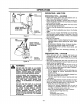
,,,,,,,,, ,,,,,,,,,, ,,,,,, ,,, HOW TO ASSEMBLE YOUR ................................................ BLOWER VACUUM BAG ASSEMBLY (Fig 2 & 3) • Open the zipper on the large end of the vacuum bag. • Insert the elbow tube, grooved end first, through the zipper opening in the vacuum bag. Then, push the grooved end of the elbow tube through the vacuum bag tube opening in the other end of the vacuum bag. Make sure the vacuum bag tube opening is flush against the tube flange.
ASSEMBLY VACUUM TUBE ASSEMBLY LOCKING TABS (Fig 4, 5, 6, & 7) • Remove the blower tube from the engine.Page 6. • Set the unit, bloweroutletup, on a flat surface.Open the vacuum inlet cover as follows: - Insert a screwdriverintolatch area. - Gently twist the tip of the screwdriverand open the vacuum intet cover with your otherhand. , Holdopen vacuuminletcoverand alignthe grooveson the uppervacuumtubewiththe lockingtabsinsidethe vacuum inlet.
OPERATION KNOW YOUR BLOWER (Fig 8) READ THIS OPERATOR'S MANUAL AND SAFETY RULES BEFORE OPERATING YOUR BLOWER. Compare the illustrations with your unit to familiarize yourself with the location of the various controls and adjustments. Save this manual for future reference. LOCK :FLER & GUARD PLUG THROTTLE TRIGGER STOP SWITCH CHOKE LEVER ASSIST HANDLE ON SOME MODF.LS (See Hardware Chart) / BLOWER TUBE FLARE NOZZLE _ CONCENTRATOR NOZZLE Figure 8 The CHOKE LEVER is used for starting a cold engine.
IIIIIIIIIIII III Jl ILl IIII I ..................................................................... 111111 OPERATION llll iiii II LU II III I[ i - ...................................................................................... ,,,,,,,,,,,,,,,,,,,, ,,, ............... BLOWER SAFETY WARNING: THE BLOWER CAUSES OBJECTS TO BE THROWN VIOLENTLY. THE OPERATOR MUST WEAR A SAFETY FACE SHIELD OR GOGGLES. ALWAYS WEAR HEAVY, LONG PANTS AND BOOTS. KEEPOTHERSAT LEAST 30 FEET (10 METERS)AWAY.
........................................ ,llllll, ii i i i ii ii ii i ii i illlll i i OPERATION • iii OPERATING / USE TIPS ASSISTHANDLE USE % ,lllll,llL i OPERATING 1,op HANDLE_ ASSISTHANDLE MODEL: 358.797982_ & 358.797950 BLOWER _ _ TIPS -- BLOWER • Always work going away from solid objects such as walls, trees, automobiles, and fences. • Clean corners by starting in corners and moving outward to flat areas to prevent an accumulation of debris which could fly into face.
OPERATION ,,, ,,,, ,, BEFORE STARTING .............................................. ENGINE: 2-CYCLE ii. AIR-COOLED ENGINE i i OIL WARNING: BE SURE TO READ THE FUEL SAFETY INFORMATION IN THE SAFETY RULES SECTION ON PAGE 2 OF THIS MANUAL BEFORE YOU BEGIN. "CRAFTSMAN 40:1 2-cycle AIR-COOLED engine oil is strongly recommended. This oil is specially blended with fuel stabilizers for increased fuel stability (extends fuef life up to 5 times longer) and reduced smoke.
OPERATION ,,,,,,,, STOPPING YOUR ,, ,, , ........................................................ ENGINE The engine may sound as if it is trying to start before the 5th pufi. If so, go to the next step i_iately. • Move the choke lever to the "Half Choke" pos_on. - Pull the starter rope sharply until the engine runs, but no more than 6 pulls. • Move the stop switch to the "Off" position. • if engine does not stop, move the choke lever to the full choke position.
......... i ii i] i CUSTOMER ,,,,,,,,,,,,,, ................................. RESPONSIBILITIES ,,,,,,,,,,,,,,,,,, MAINTENANCE ................. SCHEDULE Fill in dates as you complete regular service Before Use After Use ,,,,,,, Every 5 Hrs. Every 10 Hrs. Every Season , ,,i service Dates ....i,,, _ ,ll,l,!,l II I III ,, ,, ,, Check for damage or worn parts Check for loose fasteners and parts ............................................................. _' . ,.
CUSTOMER RESPONSIBILITIES REPLACE SPARK PLUG (Fig 14) HAZARD AND PRODUCING HARMFUL CAUTION: TO AVOID CREATING FIRE EMISSIONS, DO NOT CLEAN FILTER IN GASOLINE OR OTHER FLAMMABLE SOLVENT. The spark plug should be replaced each year to ensure the engine starts easier and runs better. Spark Plug gap should be .025". o Pull off the spark plug boot. THE HOLES IN THE AIR FILTER MUST BE FITTED OVER THE POSTS ON THE AIR FILTER COVER.
SERVICE iml AND ADJUSTMENTS =ll,llJ CARBURETOR ii i, i ill,, ii .............. i llllll lll l i i,ll PREPARATION Tools Required: Small standard screwdriver • Stop the engine. Make sure your unit is fully assembled with the tubes and nozzle in place. • Use a fresh fuel mixture with proper gasoline/oil ration (see Fueling Your Engine section). • Place the uniton a solid, flat surface free of any loose -debris. • Locate the two carburetor adjusting screws. Fig. 15.
Jl|,,uJJJ1J ............ iiiiiiiiii ii SERVICE i ii i ,,,,,,,,/ ADJUSTING .............. PROCEDURE , [_ IDLE SPEED ADJUSTMENT • Allow warm engine tO idfe. If engine wil[not idle, turn idle speed screw clockwise until the engine runs without stalling. Stop here if performance is satisfactory. • Turn screw clockwise to increase engine speed. • Turn screw counterclockwise to stow engine down. • If you feel further adjustments are necessary, proceed to following sections.
SERVICE AND ADJUSTMENTS STARTER ROPE (Fig 16-22) - Remove the 5 screws from the pulley housing, then remove the pulley housing and pulley from the engine. Replace the starter rope if the rope breaks or is badly worn. NOTE= When replacing an unbroken rope, cut the rope and allow the rope to rewind onto the pulley. REMOVE SCREWS WARNING: DO NOT REMOVE THE PULLEY WHEN REPLACING THE STARTER ROPE. ALWAYS WEAR EYE PROTECTION WHEN SERVICING THE STARTER ROPE.
SERVICE AND ADJUSTMENTS ,="U,HL,_, CLEAN/REPLACE FUEL FILTER (Fig 23 & 24) • Run fuel tank dry of fuel before proceedingwith this step. • Remove fuel cap and allow itto hang to side of motor. • Using a small pair of needle nose pliers, grasp fuel cap retainer,holdingit in tank openingand pull out. • With cap out of tank, use a small section of bent wire similar to that shown in the illustrationto catch fuel line and slowly pull from tank.
i ................................................... •.................. • .............................. STORAGE ......... I iii iiiiiiii iiiiiiiiiiiiiiiiiii :: i WARNING: ALLOW THE ENGINE TO COOL, AND SECURE THE UNIT BEFORE STORING OR TRANSPORTING IN A VEHICLE. STORE UNIT AND FUEL IN AN AREA WHERE FUEL VAPORS CANNOT REACH SPARKS OR OPEN FLAMES FROM WATER HEATERS, ELECTRIC MOTORS OR SWITCHES, FURNACES, ETC. STORE UNIT WITH ALL GUARDS IN PLACE.
............ L..J TROUBLE , .......... TROUBLE SHOOTING SHOOTING ,, ,,, iiu ; ,,,,,,,,,,,,,, ,, ............. ,,,, , ............. CHART .............................. ,,, ,, , ............. CHART SYMPTOM CAUSE REMEDY Engine willnot start or will run only for a few seconds after starting. 1. Fuel tank empty. 2. Engine flooded. 3. Spark plug not firing. 4. Fuel not reaching carburetor. 5. Carburetor requires adjustment, 6. None of the above. 1. Fill tank with correct fuel mixture. 2.
,, ,,,,,, ,,,,, ..................... REPAIR Sears Blower- Models 358.797922, PARTS 358.797950,358.797961, 358.797982, 358.797990 14 32 114 4 12. 40 ! 24 I0 !9 112 26 27 _ 115 20 10 46 34 33 47 48 49 /59 50 51 52 53 54 55 57 69 65 66 68 74 78 81 93 87 88 89 90 Manual \ 91 92 I \ I07 108 104 2t 70
REPAIR Key Part No. No.
REPAIR Carburetor _sembly Part Number PARTS 530-035263 - _-141 Carb. Repair FAt \ 17 1 2 10 8 9 _// 11 Carb. Gasket Kit r 1 \ 12 Key No. 1 2 3 4 5 6 7 I0 ii Pa_ No. 530-035014 530-035151 530-035016 530-035268 530-035214 530-035217 530-035218 530-035166 530-035164 530-035203 530-0352O8 18 13 14 15 Key No.
NOTES - 24 -
NOTES - 25 -
TABLE OF CONTENTS Safety Rules ...................................................... Product Specifications ........................................ Customer Responsibilities ................................. Warranty ............................................................ Accessories ..................................................... Assembly ........................................................... LLLIIIIIIIIIIII_III I I / Jllll 2 4 13 4 26 6 Operation ...................................
CRAFTSMAN® Operator's Manual 22cc/32cc GASOLINE ENGINE BLOWER Model No. 358.797922-32cc 358.797961-22cc 358.797990-32cc IF YOU NEED REPAIR SERVICE OR PARTS: REPAIR SERVICE 1-800-4-REPAIR (1-800-473-7247) Each Gasoline Blower has its own model number. The model number for your unit wilt be found on a decal attached to the unit. All parts listed herein may be ordered from any Sears, Roebuck and Co. Service Centers and most Retail Stores.