
Manual


NOTE: The aluminum line saver can become —
worn during use. After a groove is worn
into line saver, remove it from trimmer head, turn
it upside down, and reinstall it {with'spool re
_____
moved) to provide a new wear surface.
_______
Awahning
The line saver must be installed only from the in
side of the trimmer head. If installed on the out
side of the trimmer head, the line saver can fly
off and become a dangerous missile.________________
e. Insert the end of the line through the line saver.
Place spool in trimmer head. Press spool
down, then turn it enough to lock lugs on
spool under lugs on drive gear.
NOTE; Make sure the line is not caught between
the rim of spool and the wall of trimmer head.
f. Replace the tap button. Align the lock ring
over the catches on the hub; push the lock ring
down on the hub and turn it clockwise until the
catches lock into place.
A WARNING
All catches must be fastened and the lock tab
latched in the Lock Ring. If installed incor
rectly, the Lock Ring can fly off and become a
dangerous missile.
g. Make sure lock ring is properly fastened by
pulling on it and trying to turn it counterclock
wise. If it comes off, reinstall it properly.
h. Pull on the line to change the spool from the
locked position to the operating position.
i. Obtain the correct line length (4-6 inches) by
pressing the tap button and pulling on the
line again.
NOTE; Each time the tap button is pressed, ap
proximately 2 inches of line can be pulled from
the trimmer head.
2. Spool Replacement
a. Replace the spool when the square comers on
the lugs are rounded off, reduced in size, or bro
ken off.
b. To replace the spool, follow the instructions in
“Installing Spool with Line.”
3. Installing Line on Spool
To replace the Line on existing Spool;
a. Follow “Installing Spool w/Line,” steps
“a.—d." and remove any line remaining on
the spool.
b. Use a 40 foot length of .080” Sears Laser Line.
c. Insert 1/16” to 1/8” of the end of the line
through the hole in the spool.
Allow no more than 1/8” line to extend in
side the spool.
d. Wrap the line onto the sjiool firmly and
evenly in a clockwise direction as shown by
the arrow on the spool.
NOTE; The line must be wrapped firmly and
evenly for proper line feed.
e. Follow “Installing Spool with Line,” steps
If the line breaks off or backs up in the trim
mer head, follow “Installing Spool' w/Line,”
steps “a.—d.” Pull slack in line until the line is
tightly wound on the spool, leaving 4-~6 inches of
extended line. Continue with steps “e.~i.”
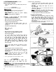
Line Saver
Catch
Lock Tab
Catch
Catch
Approximately 2 Inches of Line Can
Be Pulled From the Trimmer Head
Each Time the Tap Button is Pressed.
Tap Button
NORMAL
SPOOL,
WORN
SPOOL
4. Trouble Shooting the Trimmer Head and Line
• Doei not advance/brealu while cutting} • Weldi onto apooli
- Improperly wound onto spool. — Line size incorrect.
Line elzo incorrect. - Incorrect ipool
- Too little line outside head. - Crowding line against material being cut.
• Pulls back into head: - Cutting at higher speeds than necessary.
- Too little line outside of head, • - -
19