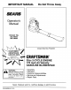
IMPORTANT MANUAL Do Not Throw Away Operator's Manual Model No. 358.798960 358.798980 Always Wear Eye Protection CUSTOMER ASSISTANCE 1-800-235-5878 HOURS (CST) ~[RAFTSMAN 32cc 2-CYCLE ENGINE Mon. - Sat. 7 a.m.• 7 p.m Sun.10a.m.·7p.m. . ® 170 mph Air Velocity GASOLINE BLOWERNAC Ii.. as WARNING Read the operator's manual and follow all warnings and safety instructions. Failure to do so can result in serious injury.
SAFETY RULES A CAUTION Always disconnect spark plug wire and place wire where it cannot contact spark plug to prevent accidental starting when setting up, transporting, adjusting or making repairs. OPERATOR SAFETY • Always wear eye protection to prevent rocks or debris from being blown or ricocheting into eyes and face which can result in blindness and/or other serious injury. • Always wear a respirator or facemask when working with the unit in dusty environments.
SAFETY RULES ~ Ii.. WARNING This power unit can be dangerous! This unit can cause serious injury or blindness to the operator and others. The warnings and safety instructions in this manual must be followed to provide reasonable safety and efficiency in using this unit. The operator is responsible for following the warnings and instructions in this manual and on the unit.
CONGRATULATIONS on your purchase of a Sears Craftsman Gasoline Blower. It has been designed, engineered and manufactured to give you the best possible dependability and performance. Should you experience any problems you cannot easily remedy, please contact your nearest Sears Service Center/Department or call the 1-800 number listed on the front of this manual. Sears has competent, well trained technicians and the proper tools to service or repair this unit. Please read and retain this manual.
TABLE OF CONTENTS Safety Rules 2 Product Specifications .
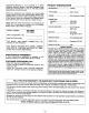
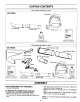
CARTON CONTENTS Parts packed separately in carton 358.798960 Flare Nozzle o ))0] Blower Tube IJ 3.2 oz. 40:1 2-Cycle Engine Oil _- _ .. D ....,................ , ... "E+!;£,: '_r :;s:~;';'":> Operator's Manual Parts packed separately in carton 358.798980 _' ...... D .,. ..... 00 __ .... =~lIXln .3.2 oz. rx8.W~¥:~"Cn 40:1 ir.?·':.
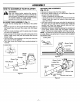
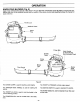
ASSEMBLY HOW TO ASSEMBLE YOUR BLOWER r>... WARNING as VACUUM TUBE ASSEMBLY (Fig. 2 & 3) • Remove the blower tube from the engine. • Set the unit, blower outlet up, on a flat surface. Open the vacuum inlet cover as follows: - Insert a screwdriver into latch area. - Gently tilt the tip of the screwdriver forward towards the blower outlet and open the vacuum inlet cover with your other hand.
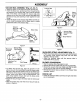
ASSEMBLY VACUUM BAG ASSEMBLY (Fig. 4, 5, 6 & 7) • Open the zipper on the large end of the vacuum bag. • Insert the elbow tube, grooved end first, through the zipper opening in the vacuum bag. Then, push the grooved end of the elbow tube through the vacuum bag tube opening in the other end of the vacuum bag. Make sure the vacuum bag tube opening is flush against the tube flange. • Close the zipper on the vacuum bag.
OPERATION KNOW YOUR BLOWER (Fig. 8) READ THIS OPERATOR'S MANUAL AND SAFETY RULES BEFORE OPERATING YOUR BLOWER. Compare the illustrations with your unit to familiarize yourself with the location of the various controls and adjustments. Save this manual for future reference. ----Plug ... Spark Primer Bulb , Assist Handle on Some Models (See Hardware Chart) j Flare Nozzle <, Blower Tube / Starter Rope Handle ...----- Figure 8 The CHOKE LEVER is used for starting a cold engine.
OPERATION HOW TO USE YOUR BLOWERNAC PRIMER BULB • The primer bulb is used to circulate fuel to the carburetor. • The primer bulb is activated by pressing on it with your thumb. STOPPING YOUR ENGINE • Move ignition switch to the "STOP" position. • If engine does not stop, turn choke knob to full. THROTTLE CONTROL GROUP (Fig. 9 & 10) THROTTLE TRIGGER • The throttle trigger allows for variable control of engine speed. • The throttle trigger is actuated by the index finger on your right hand.
OPERATION SAFETY Bl,.OWER SAFETY A WARNING The blower causes objects to be thrown violently. The operator must wear a safety face shield or goggles. Always wear heavy, long pants and boots. Keep others at least 30 feet (10 meters) away. This unit will throw objects. Keep others including children, animals, bystanders and helpers at least 30 feet (10 meters) away from the operator and unit. Stop the engine if you are approached.
OPERATION BLOWER TIPS OPERATING TIPS ~ r>... • Always work going away from solid objects such as walls, trees, automobiles, and fences. • Clean corners by starting in corners and moving outward to flat areas to prevent an accumulation of debris which could fly into face. • Be careful when working near plants. The force of the air could damage tender plants. • Direct air flow by directing the nozzle down or to one side. • Vary the air flow by adjusting your grip on the throttle trigger.
OPERATION 40:1 2-CYCLE AIR-COOLED ENGINE OIL BEFORE STARTING ENGINE ~ Ii.. CRAFTSMAN 40:1 2-cycle engine oil (AIR-COOLED) is strongly recommended. This oil is specially blended with fuel stabilizers for increased fuel stability (extends fuel life up to 5 times longer) and reduced smoke. WARNING Be sure to read the fuel safety information in the safety rules section on page 2 of this manual before you begin.
OPERATION STOPPING YOUR ENGINE • Move the ignition switch to the "Stop" position. • If engine does not stop, move the choke lever to the "Full Choke" position. A WARNING When starting the engine, hold the unit as shown in Figure 13. Do not set the unit on any surface except a clean, hard area while the engine is running. Debris such as gravel, sand, dust, grass, etc.
CUSTOMER RESPONSIBILITIES MAINTENANCE SCHEDULE Before Use Fill in dates as you complete regular service After Use Every 5 Hrs. Yearly Service Dates .;' Check for damaged or worn parts .;' Check for loose fasteners & parts .;' Clean unit & labels .;' Clean air filter .;' Replace spark plug .;' Replace fuel filter BEFORE USE GENERAL RECOMMENDATIONS The warranty on this blower does not cover items that have been subjected to operator abuse or negligence.
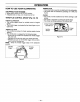
CUSTOMER RESPONSIBILITIES EVERY 5 HOURS YEARLY CLEAN AIR FILTER (Fig. 15) ~ 1">.. REPLACE SPARK PLUG (Fig. 16) CAUTION To avoid creating fire hazard and producing harmful emissions, do not clean filter in gasoline or other flammable solvent. The holes in the air filter must be fitted over the posts on the air filter cover. When installing the air filter/cover assembly, be sure that the filter does not hang on the choke lever screw.
CUSTOMER RESPONSIBILITIES REPLACE FUEL FILTER (Fig. 17 & 18) The fuel filter should be replaced after each season. Never operate your unit without a fuel filter. Be careful not to damage fuel line while removing the fuel filter. • Run fuel tank dry of fuel before proceeding with this step. • Remove fuel cap and allow it to hang to side of motor. • Using a small pair of needle nose pliers, grasp fuel cap retainer, holding it in tank opening and pull out.
SERVICE AND ADJUSTMENTS STARTER ROPE (Fig. 19, 20, 21,22, 23, 24 & 25) ~ .Ii.. • Remove the 5 screws from the pulley housing, then remove the pulley housing and pulley from the engine . WARNING Do not remove the pulley when replacing the starter rope. Always wear eye protection when servicing the starter rope. The recoil spring, located beneath the pulley, is under tension. If the spring pops out, serious injury can result. Remove Screws Replace the starter rope if the rope breaks or is badly worn.
FOR CALIFORNIA RESIDENTS ONLY WHEN SEEKING SERVICE IN CALIFORNIA CALIFORNIA EMISSION CONTROL WARRANTY STATEMENT YOUR WARRANTY RIGHTS AND OBLIGATIONS The California Air Resources Board and Sears, Roebuck and Co., USA, are pleased to explain the emissions control system warranty on your 1995 lawn and garden equipment engine. In California, new utility and lawn and garden equipment engines must be designed, built, and equipped to meet the State's stringent anti-smog standards.
WHAT IS COVERED-REPAIR OR REPLACEMENT OF PARTS-Repair or replacement of any warranted part will be performed at no charge to the owner at an approved Sears servicing center. If you have any questions regarding your warranty rights and responsibilities, you should contact your nearest authorized service center or call Sears at 1-800-473-7247.
SERVICE AND ADJUSTMENTS ~~ 3/16"- " Rope Tai Figure 23 Figure 24 • Guide rope inside the pulley, then through pulley hole. Figure 23. • Wrap rope counterclockwise around the pulley ratchet and tuck the loose end back under the rope, leaving about a 1 inch tail next to the retainer rib. The end of the rope should not go more than 1/4" past the end of the retainer rib. • Install and tighten the retainer screw/washer. Figure 24. NOTE - Do not overtighten the retainer screw.
SERVICE AND ADJUSTMENTS CARBURETOR ADJUSTMENTS Carburetor adjustment is critical and If done Improperly can permanently damage the engine as well as the carburetor. Please read all Instructions and consult the Trouble Shooting section of this manual before beginning this process. If the engine does not operate according to these instructions after repeating the adjusting steps, do not use the unit. For further assistance. please call our customer assistance helpline at 1-800-235-5878. ~ .I'i..
STORAGE Fuel stabilizer is an acceptable alternative in minimizing the formation of fuel gum deposits during storage. Add stabilizer to the gasoline in the fuel tank or fuel storage container. Always follow the mix instructions found on stabilizer containers. Run engine at least 5 minutes after adding stabilizer to allow the stabilizer to reach the carburetor. Immediately prepare your unit for storage at the end of the season or it will not be used for 30 days or more.
TROUBLE SHOOTING POINTS TROUBLE SHOOTING CHART SYMPTOM CAUSE CORRECTION Engine will not start or will only run only for a few seconds after starting. 1. 2. 3. 4. 5. 6. 1. 2. 3. 4. 5. 6. Engine will not idle properly. 1. Carburetor set too fast or too slow. 2. Carburetor requires adjustment. 3. None of the above. 1. See "Carburetor Adjustments." 2. See "Carburetor Adjustments." 3. Contact your SEARS Service Center/Dept. Engine will not accelerate, lacks power, or dies under a load. 1. 2. 3. 4. 5.
REPAIR PARTS Sears Blower - Models 358.798960 & 358.798980 2 #3-' 6 23 41 42 ~.
REPAIR PARTS Key No. Part No.
REPAIR PARTS Carburetor Assembly Part Number 530-069730 (WA219-B) Carbo Repair Kit , 1 Key No. 1 2 Part No. 530-069729 530-038403 Description Carburetor Repair Kit Limiter Cap-Single Needle Vacuum Tube/Blower Tube Ass'y. 4 i KEY NO. PART NO. 530-095358 530-037250 530-069750 530-038555 530-095359 1 2 3 4 5 25 i DESCRIPTION Collection Bag Shoulder Strap Vacuum Tube Tube & Nozzle Ass'y.
CRAFTSMAN® SSAiRlS Operator's Manual 32 cc 2-CYCLE ENGINE 170 mph Air Velocity GASOLINE BLOWERNAC Model No. 358.798960 358.798980 Each Gas Blowers' has its own model number. The model number for your unit will be found on a decal attached to the unit. All parts listed herein may be ordered from any Sears, Roebuck and Co. Service Center and most Retail Stores.