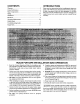
I SEARS OWNER'S MANUAL MODEL NO. 390.2508 CRAFTSMAN° CAUTION: Read andFollow All Safety Rulesand Operating Instructions Before FirstUse of This Product. Save ThisManual For Future Reference. HYDROGLASS ® SHALLOW WELL JET PUMP • Safety Instructions • Installation • Operation • Troubleshooting • Repair Parts Sears, Roebuck and Co., Hoffman Estates, IL 60179 PRINTED IN USA. U.S.A.
CONTENTS WaL'ranty Pump INTRODUCTION .............................................................................. 2 Performance .............................................................. 3 Major Components .............................................................. 3 Piping ................................................................................ Installation Electrical 4 ..............................................................................
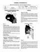
GENERAL INFORMATION Table h Pump Performance Pump Chart (In Gallons Per Minute) Suction Discharge Discharge Pressure Pumping Depth in Feet Model Description Size Size P.S.I. 5' 10' 15' 20' 390.2508 1/2 HP Standard S.W. Jet 1-1/4" 3/4" 40 7.3 6.2 5.2 4.2 PIPING MAJOR COMPONENTS AND WHAT THEY DO Piping Relief Valve A Shallow well jet pump can be installed on a dug well, drilled well or with a driven point.
PIPING Cased Well INSTALLATION ff horizontal suction pipe is more than 25' long, priming plug at well head to allow filling of pipe. Open Water SEARS jet pumps should be used vdth (see Figure 2, Page 3). For mounting chase tank fittings Kit No. 2788. install a Captive Air® Tanks pump to tank, pur- SEARS Captive Air* Tanks are pre-charged with air at the factory. Check the tank Owner's Manual to find if air charge needs adjustment. Pump model 390.2508 requires 30 pounds for proper operation.
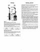
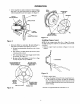
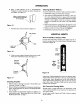
ELECTRICAL Disconnect Motor Switch power before working Settings on pump, motor, pressure switch, or wiring. Dial Type Voltage Selector If the motor can operate at either 115 or 230 volts, it is set at the factory to 230 volts. Do not change motor voltage setting if line voltage is 230 volts, or if you have a single voltage motor. NOTICE: Remove Never wire a 115 volt motor Hotor to a 230 volt line. End Cover Figure 5 - Voltage Set To 230 Volts, Dial Type To change to I 15 volts: 1.
ELECTRICAL WIRING CONNECTIONS ,AWARNING] Fire hazard. Connection Incorrect voltage can cause 1. a fire or seriously damage the motor and voids the warranty. The supply voltage must be within + 10% of the motor nameplate voltage. Procedure: Connect the ground wire first as shown in Figure 6. The ground wire must be a solid copper wire at least as large as the power supply wires. 2. There must be a solid metal sure switch and the motor tion.
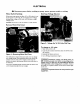
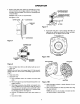
OPERATION Disassembly and Assembly of Pump Priming the Pump NOTE: To properly prime the pump, install a pipe tee in the discharge piping, similar to that shown in Figures 1 and 2 on Page 3. [& CAUTION Never run pump dry. Running pump without water may cause pump to overheat, damaging seal and possibly causing burns to persons handling pump. Fill pump with water before starting. &WARNING tempting Your SEARS pump is designed for ease in servicing.
OPERATION 3. Remove seal plate from motor by inserting two screwdrivers between the seal plate and the motor flange. Pry seal plate off motor flange. This will force rotating portion of seal off shaft. CARDBOARDWASHER NOTE: Be sure you do not scratch shaft! See Figures 7 & 8. MOTOR FLANGE SCREWDRIVER D WITHSEAL HALF CUP/St .=L_ PUMPBACK Figure MOTOR 3/4" PIPE 9 F. Reassemble seal plate to motor flange. BE SURE it is right side up: index pins should be down; seal plate is marked at top.
OPERATION I. Screw impeller on shaft (clockwise) while holding shaft wzth 7/16" open end wrench on shaft flats. This v_fll automatically locate seal in place. See Figure 11. SEAL PLATE HOLES MUST LINE UP DIFFUSER FACE OF SEALING WASHER IMPELLER HUB SHAFT SHOULDER % BE SURE NIBS ENGAGE NOTCHES RUBBER DRIVE RING Figure 13 Figure Installing II Remount diffuser on seal plate. Be sure diffuser right side up as follows (see Figures 13 and 14). a. Rib next position; b.
OPERATION B. Place a small amount of No. 2 non-hardening Permatex on surface of insert as shown. Smooth out with finger. See Figure 15. Cleaning To remove Shallow debris from venturi 1. Disassemble Wipe on small amount of non-hardening Permatex on this surface Figure 15 C. Pull insert into cavity as shown in Figure 16. Well pump Jet or nozzle, per instructions proceed as follows: on Page 7. 2. Turn venturi counterclockwise and remove it. The nozzle is now exposed.
TROUBLESHOOTING SYMPTOM POSSIBLE CAUSE(S) Motor will not run switch CHART CORRECTIVE ACTION 1. Disconnect 2. Fuse is blown is off 1. Be sure switch 3. Starting switch 4. Wires at motor are loose, disconnected, or wired incorrectly 4. Refer to instructions 5. Pressure 5. Cleanbyslidingpiecesofplainpaperbctweencontacts 2. Replace is defective switch contacts is on false 3. Replace sta_ing are dirty on wiring. Motor runs hot and 1. Motor is wired 2. Voltage is too low 2.
REPAIR PARTS 1 28 2 4 6 7 8 9 10 26 11 25 24 23 AVC Port 22 21 20 To Order Parts, Sears Product Call 18 17 Service, 1-800-366-7278 2305 0296 J 14 Model Key No, Part Number 13 J 12A / 12B 390.2508 Qty.
SEARS OWNER'S MANUAL I:RRFTSMRN* HYDROGLASS ® SHALLOW WELL JET PUMP Forthe repair or replacementpartsyou need Call 7 am - 7 prn, 7 days a week 1-800-366-PART MODEL NO. (1-800-366-7278) 390.2508 Forin-homemajorbrandrepair service Call24 hours a day, 7 days a week 1-800-4-REPAIR (1-800-478-7247) The model number of your Shallow Well Jet Pumpwill be found on a plate attached to the pump discharge connection.