F642-2292 SEARS OWNER’S MANUAL MODEL NO. 390.252151 CAUTION: CRAFTSMAN Read and Follow SHALLOW WE LL Oh teeny Mes ond « | WATER SYSTEM Before First Use of This Product. * Safety Instructions his Manual * Installation Save This Manual For « Electrical Future Reference. ) * Maintenance * Repair Parts Sears, Roebuck and Co., Hoffman Estates, IL 60179 U.S.A. PRINTED iN U.S.A. Form No. FE42.2292 (Rev.
CONTENTS INTRODUCTION INTRODUCTION/WARRANTY 2 Please read our instructions before installing and using PUMP PERFORMANCE 3 your Shallow Well Water System. This will help you ob Major COMPONENTS 4 INSTALLATION built into this equipment. It will also help you avoid any needless service expense resulting from causes be ELECTRICS] : ond our control which are not covered by our war. OPERATION . Sty. ’ MAINTENANCE...
SAFETY INSTRUCTIONS (Continued) 6. Disconnect electrical power source before in8. Line voltage and frequency of electrical power sup stalling or working on pump. ply must agree with motor nameplate. 7. Ground pump with a ground wire run from ground. Use of fuses or wire smaller than size recommended ing lug on motor to a grounded lead in the service in owner's manual can cause overheating, possible panel, fires, and will void warranty.
BASIC TOOLS AND MATERIALS NEEDED Plastic Pipe Installation Tools Pipe Wrenches Screwdriver Knife or Saw to Cut Plastic Pipe Tire Pressure Gauge Galvanized Steel Pipe Installation Tools Pipe Wrenches Screwdriver Pipe Cutting and Threading Tools Tire Pressure Gauge MAJOR COMPONENTS AND WHAT THEY DO Impeller and Jet Impeller turns with motor shaft, causing water to fly out from its rim by centrifugal force. Impeller rotation creates a vacuum which pulls in more water.
INSTALLATION 1. Wrap male pipe threads being attached to pump ‘with one or two layers of Teflon tape. Cover entire threaded portion of pipe. 2. Do not over tighten threaded fittings in the plastic pump. Be sure you do not try to tighten joint past thread stop in pump port! 3. If leaks occur, remove fittings, clean off old tape, re wrap with two to three layers of tape and remake the connection. If joint still leaks, replace the fittings (fittings may be undersized). 4.
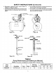
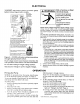
ELECTRICAL [warning Disconnect power at service panel before connecting pressure switch. Motor wires To convert from 7 23010 115 Volts: || Move whoa wire ¢ are connected 0 these wo brass scows. ticktacktoe {Sp fom B1n A. >) Clamp Move slack wis { |g power fmm ALY 2 care to . prevent strain on Motor Ground terminal Cro 2 screws. a white w/ Hack Tracer I Connect gratin (of bare copper) ground wire to green Ground screw, Conn eat black and white power supply wits 16 Hies twa Craws, ane wire to pate screw.
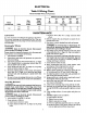
ELECTRICAL Table II Wiring Chart Recommended Wire and Fuse Sizes Distance in Feet from Motor to Meter Branch 0 101 201 301 401° Max, Fuse* Motor Load Rating 100 200" 300° 00 500° Horsepower Volts Amps. Amps Wire Size 118 230 MAINTENANCE Lubrication It is not necessary to lubricate the pump or its motor. The motor bearings are lubricated for life. The mechanical shaft seal in the pump is water lubricated and self-adjusting. Draining for Winter Risk of electric shock. Disconnect power before working on unit.
MAINTENANCE NOTICE: Do not over tighten; you may twist studs off of tank. If you have a torque wrench, tighten to 85 inch-pounds torque. 18. Stand tank on feet and reconnect piping. 19. Recharge tank to proper air pressure (see Page 5). 20. Reconnect hoses and pressure switch tube; prime pump (see Page 6). Air Valve Replacement 1. Follow steps 1 through 5 under “Vinyl Bag Removal”, Page 7. 2. Cut valve off as close to tank as possible. Push remaining portion back into tank, 3.
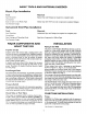
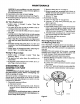
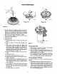
MAINTENANCE 419.0194 Figure 6 3, Remove pump back half from motor by unscrewing four (4) nuts. Pry back half off motor by inserting two (2) screwdrivers between the back pump half and the motor flange. This will force rotating portion of seal off shaft. See Figure 5, Page 8, 4. Place back half of pump on flat surface and tap out ceramic seat. See Figure 6. 5. Clean seal cavity. 6. Install new seal. A. Clean polished surface of ceramic seat with clean cloth. B.
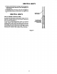
HELPFUL HINTS 3. Flush out the debris by running water through the nozzle in the same direction as the dislodging tool was inserted. 4. Reinstall nozzle and venture, Do not over tighten! 5. Reassemble pump per instructions on Pages 8 and 9. HELPFUL HINTS How to Handle a Gaseous Well In some areas well water contains gases which must be allowed to escape before the water is used, This can be done as shown in Figure 9.
TROUBLESHOOTING GUIDE TROUBLE POSSIBLE CAUSES REMEDIES Motor will not run 1. Disconnect switch is off 2. Fuse is blown 3. Starting switch is defective 4. Wires at motor are loose, disconnected, or wired incorrectly *5, Motor is wired incorrectly 6. Pressure switch contacts are dirty Be sure switch is on Replace fuse Replace starting switch Refer to instructions on wiring Clean by sliding piece of plain paper between contacts Motor runs hot and overload kicks off *1. Motor is wired incorrectly 2.
REPAIR PARTS SEARS 1/2 HP SHALLOW WELL WATER SYSTEM (Pump Only) Model 390.252151 las ‘Wiring omitted i] for clarity To Order Parts In the U.S.A, Call Sears Product Service, 1-800-366-7278 To Order Parts outside the U.S.
REPAIR PARTS Koy Mode! 390.252151 Part No. 1/2 HP Description = J218-853C Motor 115/280V 60 Cycle {includes Key Nos.
REPAIR PARTS SEARS 1/2 HP SHALLOW WELL WATER SYSTEM (Tank Only) Model 390.252151 "To Order Parts outside the U.S.A, Call Your local Sears Service Center or Store REPAIR PARTS Model 380.252151 Key 1/2 HP Qty. No. Part Number Used Description 1 U231.2891 Ark Assembly (Includes Diaphragm, Valve, Nuts, & Inlet Flange) . 20-13 1 Bag Tiny! . U12-160 t 1 Air Naive w/Cap 2 Ut-167 1 Inlet Flange .
SEARS OWNER’S MANUAL Model No. 390.252151 The model number of your Shallow Well Water System will be found on the pump body.