Operators Manual ® 5.5 H.R OFT TOP No. 486.245041 • o • • ,, CAUTION: Before using this product, read this manuaU and follow aH Safety RuUes and Operating Instructions. iMPORTANT Safety AssembLy Operation Maintenance Parts - READ TH_S FIRST!!! For Missing Parts or AssembUy Questions PUease Call 866-576-8388 Mon.-Fri. 7 am - 5 pm CST. FAX 217-728-2032 or e-maiU info@aqd-fab.com Missing parts will be sent UPS in 24 hours directly to your home. SEARS, ROEBUCK AND CO., HOFFMAN ESTATES, IL 60179 U.
WARRANTY ................................................................ 2 SAFETY RULES .......................................................... 3 ACCESSORIES AND ATTACHMENTS ....................... 5 FULL SIZE HARDWARE CHART ................................ 6 CARTON CONTENTS ................................................. 8 ASSEMBLY .................................................................. 9 OPERATION .............................................................. 18 MAINTENANCE .............
Any power equpiment can cause injury if operated improperly or if the user does not understand how to operate the equipment. Exercise caution at all times when using power equipment. Read and follow all instructions in this manual before attempting to assemble or operate this equipment. Failure to comply with these instructions may result in personal injury. Keep this manual in a safe place for future reference and for ordering replacement parts. Read this operating and service instruction manual carefully.
lira TO AVOID SERmOUS mNJURY • • , • • • • • Read Owner's Manual and all safety labets on machine before starting and using machine. Do Not remove top cover or attempt to empty contents of cart whi{e engine is running. Do Not stand behind cart in exhaust discharge area whi_e engine is running. Keep hands, feet, face, _ong hair and cmothing out of chipper in_et, vac in_et, and discharge area. There are ROTATING BLADES inside these openings. Wear approved safety glasses and gloves.
THESE ACCESSORIES WERE AVAILABLE WHEN THE UNiT WAS PURCHASED. THEY ARE ALSO AVAILABLE AT MOST SEARS RETAIL OUTLETS AND SERVICE CENTERS, MOST SEARS STORES CAN ORDER REPAIR PARTS FOR YOU WHEN YOU PROWDE THE MODEL NUMBERS OF YOUR TRACTOR AND VAC SYSTEM. h k _' t- f The Hand Wand Attachment, Model 486.24509 provides a 12' x 5" diameter hose to clean around shrubs, patios, window wens and other areas not accessible to the tractor.
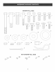
SHOWN FULL SIZE ] i i D C J J J i i ii ii i $ FI O __ U V _1 _ J X Z Y .
ATTENTmON! Keep centente ef each hardware CONTENTS Ref, Qty. A B C D F G I J L M N 3 2 1 2 4 4 25 4 4 12 2 OF LARGE package VAC HARDWARE Description Hex Bolt, 3/8" x 3" Shoulder Bolt Hex Bolt, 1/2" x 1-1/2" Hex Bolt, 1/4" x 1-3/4" Hex Bolt, 1/4" x 1-1/4" Hex Bolt, 5/16" x 1" Hex Bolt, 1/4" x 3/4" Carriage Bolt, 1/4" x 3/4" Hex Bolt, 5/16" x 3/4" Thread Forming Bolt, Truss Head 5/16" x 3/4" Bolt, Curved Head 1/4" x 1" CONTENTS OF SMALL separate Ref. Qty.
4 ..... 3 18 19 20 j21 22 23 25 26 29 CARTON Refo 1 2 3 4 5 6 7 8 9 10 11 12 13 14 15 16 Qty. 1 2 2 2 1 2 1 1 1 1 2 1 2 2 1 1 32 31 30 27 CONTENTS Description Cover Top Connecting Tube Support Tube, R,H, Support Tube, LH, Elbow (Discharge Chute) Deck Adapter Hose2 Hose Hanger Rod Assembly Hose Adapter (Nozzle) Engine Hose Clamps Tailgate Cart Bodies Wheels Tailgate Reinforcement Bracket Wheel Support Ref. Qty.
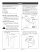
Thisunitis shippedWFHOUTGASOLINE orOIL. After assembly, seeseparateenginemanualforproperfuel andengineoil recommendations, TOOLS REQUIRED FOR ASSEMBLY (1) Screwdriver (1) Pliers (1) 3/8"Wrench (2) 7/16"Wrenches (2) 1/2"Wrenches (2) 9/16"Wrenches (1) 3/4"Wrench(2)if hitchplateinfig,21 is used REMOVAL , , Fit the tailgate reinforcement bracket around the end of the cart body, Fasten it to the top flanges of the cart body using two 1/4" x 3/4" hex bolts and 1/4" nylock nuts. Do not tighten yet.
, , , Pul!thecartbodyhalvestogether. Place the rear tongue onto the wheel support and the latch stand bracket. Assemble the axle through the wheel support and the tongue. Fasten the axle to the wheel support using two 1/4" x 1=3/4" hex bolts and 1/4" nylock nuts. See Figure 6. Tighten the four truss head bolts. Tighten the six hex bolts in the sides of the cart. Tighten the three hex bolts in the bottom of the cart, keeping the bottom aligned.
, Flipthecartoversothatit restson itswheels. Assemblethefronttongueontopofthereartongue usingthree3/8"x 3"hexboltsand3/8"hex!ocknuts. Seefigure8. HINT:Foreasierassembly, supportthereartonguewith a b!ockofwood. Assemblethehitchpintothehitchbracketand tongue,securingit withthe 1/8"haircotterpin.See figure8. Place the R.H. Front Tube Support Bracket under the top flanges of the cart, as shown in figure 10. Fasten the bracket to the cart using three 1/4" x 3/4" hex bolts and 1/4" nylock nuts.
To install the fabric cart cover: Place the support tubes down into the front and rear tube support brackets, with the tube's welded brackets facing the center of the cart, Assemble the top connecting tubes to the support tubes using four 1/4" x 1ol/4" hex bolts and 1/4" nylock nuts, Tighten unti! the end of the bolt extends through the nut, See Figure 12, 114"× 1-1/4" HEX BOLT 1, Unzip the cover's rear flap and place cover on top of the support tubes, making sure that the zippered flap is at rear of car
, Assemble a plastic wheel to each engine mount bracket using a 3/8" shoulder bolt and 3/8" hex lock nut. See Figure 14. Remove the hex bolts, lock washers and hex lock nuts from the two holes in the impeller housing as shown in figure 16. Assemble the hose hanger bracket to the two holes using the bolts, lock washers and lock nuts which you removed.
Loop the 25" tarp strap under the hose. Fasten the hooks to the hose hanger rod assembly. See figure 20. Place the hose hanger rod assembly down into the hose hanger bracket on the impeller housing assembly. See figure 18. HOSE HANGER ASSEMBLY '\ '/ BOSEHANGER ASSEMB_ FIGURE 20 FIGURE 18 , Place a hose clamp onto the end of the hose. Push the hose onto the hose adapter (nozzle). Tighten the hose damp onto the hose and hose adapter. Do not collapse the hose adapter when tightening the clamp.
ASSEMBLING THE #62468 TO THE MOWER DECK DECK ADAPTER Position the adapter over the deck opening, and check for fit of cutout as shown in figure 23. Trim cutout, if necessary, to allow tilting of adapter, keeping the fit as close as possible for best vacuum suction. NOTE: Not al! of the parts in the deck adapter hardware package will be used for any one particular fit up. . NOTE: Remove the mower discharge deflector from your mower deck. Save the deflector and hardware for remounting deflector.
Assemble theadapterbrackettothedeckusingtwo 5/16"x 1-1/4"hexbolts,5/16"flatwashersand5/16" nylocknuts.Seefigure25. FOR 1990 AND NEWER MURRAY WiTH A 38" OR 40" DECK NOTE:It maybenecessary to useextra5/16"flat washerstoshimunderthebracketnexttothedeck surface.Tenextrawashershavebeenfurnishedas shims.Seefigure25.
FOR 1990 AND NEWER WITH A 46" DECK MURRAY TRACTORS Tape 46" template onto deck adapter, Mark and then cut out adapter, Fasten the angle bracket and the mounting bracket to the mower deck as shown in figure 34, Use two 5/16" x 1" carriage bolts, 5/16" fiat washers and 5/16" nylock nuts, The bolt heads go on inside of mower deck, Drill two 5/16" diameter holes in the deck adapter that will align with the holes in the angle bracket and the mounting bracket, Assemble the deck adapter to both brackets using t
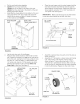
KNOW YOUR VAC SYSTEM Read this owner's manual and safety rules before operating your Vac System, Compare the illustration below with your Vac System to familiarize yourself with the various controls and their locations. BOOT LATCH LOCK REAR FLAP LEVER \ CHOKE CONTROL THROTTLE LATCH LOCK LEVER Locks the cart bed down to the tongue. Releases to allow cart to be tipped back for dumping= CONTROL REAR FLAP Zippered flap opens to allow contents of cart to be emptied.
HOW TO START YOUR VAC SYSTEM CAUTION: To avoid possible injury, be sure that no one is near the cart before WARNING: Never start or run the engine without a!! covers being properly attached to the blower housing and cart. releasing the latch lock lever. , , , , , , , Check oil and gas in Vac engine. Attach spark plug wire to spark plug. Move choke lever on engine to CHOKE position. (A warm engine may not require choking.) Move throttle control lever on engine to FAST position.
CUSTOMER RESPONSIB_LIT_ES Read and follow the maintenance schedule and the maintenance MAINTENANCE SCHEDULE Fil! in dates as you complete regular service. Check for loose procedures listed in this section. _,.J _ ,o_ fasteners Service Dates X Check cover Check tire pressure X X che_keng!ne_!1!eve! X Lubricate X Clean ! lXl IX Maintain engine per instructions below and in engine manual.
Clean the engine and the entire unit thoroughly. Refer to engine manual for correct engine storage instructions. it is important to prevent gum deposits from forming in essential fuel system parts such as the carburetor, fuel filter, fuel hose or tank during storage. Also, alcohol blended fuels (called gasohol or using ethanol or methanol) can attract moisture which leads to separation and formation of acids during storage. Acidic gas can damage the fuel system of an engine while in storage.
REPAIR PARTS FOR MODEL 486.245041 11 26 SOFTTOP MOW-N-VAC CART 22 \ \ 32 / 11 12 31 12 17 12 23 20 lO \ \ 13 j 28 14 19 27 RER NO. PART NO. QTY. 1 2 3 4 5 6 7 8 9 10 11 12 13 14 15 16 24096 62457 23487 24497 24984 43594 43093 43601 48637 43014 43012 47189 1509-69 HA20186 43814 23490 2 1 1 1 1 2 2 4 2 2 25 31 2 1 12 1 DESCRIPTION REFo NO. Cart Body Tailgate Reinforcement Bracket Wheel Support Latch Stand Bracket Axle, Wheel 1" Dia.
REPAIR PARTS FOR MODEL 486.245041 f.f SOFT TOP MOW-N-VAC 1" 23 J I I \ \ \ 27 37 14 I 38 4O / / TRACTOR 12 32 _ 13 24
REPAIR PARTS FOR MODEL 486.245041 RER NO. PART NO. QTY. 1 2 3 4 5 6 7 8 9 734-0973 24957 24956 43182 43840 43085 738-0373 47810 63375 2 2 1 4 2 4 2 17 1 10 11 12 13 14 15 16 17 18 19 2O 21 22 23 24 25 26 27 28 29 3O 31 32 781-0635 1 728-3001 3 43661 4 47189 7 1273120113-E 1 222261 1 63227 1 46420 1 43792 1 43793 2 48634 2 64647 2 64648 2 48640 1 43790 1 43088 4 23540 1 1543-69 9 43020 1 712-3083 1 43352 1 43081 12 43830 1 DESCRIPTION SOFTTOP RER NO. PART NO. QTY.
REPAIR PARTS FOR MODEL 488.245041 SOFTTOP mMPELLER HOUSING ASSEMBLY RER NO. PART NO. 1 629=0241A 2 3 4 5 24634 24633 43182 710-0772 6 710=1268 43063 7 8 712-0421 47810 9 43086 10 11 719=0330A 12 725-1700 RER NO. QTY. DESCRiPTiON 1 1 1 10 3 2 3 3 12 13 1 1 13 14 15 16 17 18 19 2O 21 22 23 Harness, Wire Housing Ass'y. Inner Housing Ass'y.
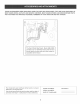
SIGHT AND HOLD THIS LEVEL WITH A VERTICAL TREE @ A POWER POLE 03 O A CORNEFI OF A BUILDING _ ..... OR A FENCE POST O O @ o I E _fl _o _o b,('4 o W_"- @ OO. " "J_o £. I >, 0 i ii v@ o @ 4_ @ 4_ _b J_ @ I CAUTION: Do not operate your tractor and Vac System on a slope in excess of 10 degrees. Be sure of your tractor's towing and braking capabilities before operating on a slope. Avoid any sudden turns or maneuvers while on a slope.
;;;;;;;;;;;;;;;;; For repair of major brand appliances in your own home... no matter who made it, no matter who sold it! !!!!!!!!!!!!!!!!! I°800°4°MY°HOMESM Anytime, day or night www._e_r_.oom To bring in products such as vacuums, lawn equipment and electronics for repair, call for the location of your nearest Sears Parts & Repair Center. 1-800-488-1222 Anyfime, dayornight wwwosears.