Owner's Manual I CRAFI",'SMAN+ I 42"- 2 STAGE SNOW THROWER TRACTO R ATTAC H M E NT Model No. 486.248531 • • • • • CAUTION: Before using this product, read this manual and follow all Safety Operating and Instrucctions. IMPORTANT - READ THIS For Missing Parts or Assembly Please Call 217-728-8388 Mon.-Fri. 7 Safety Assembly Operation Maintenance Parts FIRST!!! Questions am - 5 pm CST. FAX 217-728-20322 or e-mail info@agri-fab.
ACCESSORIES SAFETY FULL SIZE ........................................................... .......................................................... 2 3 HARDWARE CHART ................................. CARTON ................................................. ASSEMBLY .................................................................. OPERATION .............................................................. MAINTENANCE ..........................................................
Anypowerequipmentcancauseinjury if operatedimproperlyor if the userdoesnot understandhowto operate the equipment.Exercisecautionat all times,whenusing powerequipment. • Readthis owner'smanualcarefullyandknowhow to operate • • • • yoursnowthrowerandhowto stopthe unitanddisengagethe controlsquickly. • Neverallowchildrento operatethe equipment. • Neverallowadultsto operatethe equipment withoutproperinstruction. • Keepthe areaof operationclearof allpersons, especiallysmalllchildren,andpets.
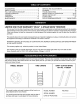
SHOWN ACTUAL SIZE \ P SPARE PARTS BAG Store these two bolts and nuts in a safe )lace until needed, (See page 17.) NOT SHOWN ACTUAL SIZE jAA HH REF. A B C D E F G H I J K L M N O P Q QTY. 1 4 2 6 2 4 2 2 6 4 1 10 12 6 2 2 2 DESCRIPTION Hex Bolt, 1/2" x 1-1/4" Hex Bolt, 3/8" x 1" (Thread Forming) Hex Bolt, REF. R 5/16" x 1-3/4" Hex Bolt, 1/4" x 1" Slotted Truss Head Bolt, 3/8" x 1" Carriage Bolt, 3/8" x 1" Carriage Bolt, 5/16" x 1-3/4" Carriage Bolt, 5/16" x 1-1/4" QTY.
CARTON 1. 2. 3. 4. 5. 6. 7. CONTENTS Cross Brace (Weight Tray) Side Brace (Weight Tray) Right Hand Side Plate (Stamped "R") Left Hand Side Plate (Stamped "L") Anti-rotationn Bracket Chute Crank Rod Assembly Support 8.
TOOLS (2) (2) (2) REQUIRED INSTALLING FOR ASSEMBLY 7/16" Wrenches 1/2" Wrenches 9/16" (2) (1) SIDE PLATES ON TRACTOR Wrenches 3/4" Wrenches Knife ADDITIONAL REQUIRED General Purpose Grease REMOVAL • OF PARTS FROM CARTON Remove all parts and hardware packages from the carton. Lay out parts and hardware and identify using the illustrationns on pages 4 and 5. NOTE: Not all of the supplied parts and hardware will be needed for your particular tractor.
Assemble a shoulder bolt, a 3/8" lock washer and a 3/8" hex lock nut to the bottom hole in each side plate. See figure 3. Proceed to page 8.
INSTALLING HANGER For better clearance, arms using BRACKETS lower the tractor's suspension the attachment lift lever. On Tractors With Foot Rest Brackets (Figure 7) • Remove the bolt and nut that fasten the L.H. and R.H. foot • rest brackets to the frame. S Attach the L.H. Hanger Bracket (mark inside of the t carriage nuts.
INSTALLING • CLUTCH/IDLER Turn the clutch/idler place the ASSEMBLY assembly upside down and extra tensioning shown in figure 11. chain through the hole USE THIS HOLE FIGURE • • 11 Hook the loose spring through the end of the tensioning chainn. See figure 12. Hook the other end of the spring onto the bottom of the bolt and nut which secure the idler pulley to the upper idler arm.
ASSEMBLY Place the OF THE SNOW THROWER • Tilt the snow thrower back down to the ground. lift handle into the lift bracket on the right side of the snow thrower. Fasten the handle to the bracket lock two 5/16" x 1-3/4" hex bolts, 5/16" and 5/16" hex nuts. See figure 15. LIFT HANDLE _.
CHUTE CRANK BRACKET 5/16" x 1" \\ \ .,dw,,,.,,,,. _CARRIAGEBOLT CHUTE CRANK ROD ROD SUPPORT BRACKET J / _16"FLAT WASHER WASHER 5/16"LOCK _ "5/16"HEX NUT FIGURE • 19 LEFT SIDE VIEW Coat the top of the ring around the discharge opening general purpose grease. See figure 20. Place the discharge chute (facing forward) onto the ring. Place the anti-rotation bracket on top of the chute aligning it with the holes on the right hand side of the flange.
INSTALLINGTHE • AUGER BELT INSTALLING The auger belt comes preassembled to the pulleys on the snow thrower housing. Make sure the belt passes over the top of the auger pulley and then twists 1/4 turn to pass underneath each side idler pulley. The "V" side of the belt must mate with the grooves of the pulleys. See figure 22. AUGER PULLEY TWIST 1/4 TURN IDLER PULLEY THE A Lift the front of th in the mounting p the left side of th through the holes cotter.
ATTACHING WEIGHT TRAY TO TRACTOR Loosen the top hex bolt on each side of the tractor frame at the rear. Assemble the slotted end of the side braces down onto the loosened bolts. Do not tighten yet. See figure 25. Place the fasten the weight tray on top of the tractor hitch side braces to carriage 5/16" lock nuts. Do not tighten yet. • and it using two 5/16" x 1" washers and 5/16" hex See figure 25.
If yourtractoris notequippedwithrearreflectors, assemble tail reflectorstothe rearfender. Placethe reflectorsascloseto the bottomofthe fenderand asfar apartas the shapeof the will allow.Seefigure28.
KNOW YOUR Read this SNOW THROWER owner's manual and safety rules before operating our snow thrower. Compare the illustration below with your snow thrower to familiarize yourself with the vario _E TRIGGER LIFT HANDLE UPPER CHUTE LOWER CHUTE SKID SHOE SCRAPER SPIRAL R.H.& L.H. CHUTE TILT HANDLE Pivots the Upper Chute up or down to control the angle and distance of discharge. CRANK ROD Rotates the Lower and Upper Chutes to control the direction of discharge.
RAISING AND LOWERING • • To raise, push down on the lift handle until the snow thrower locks in the raised transport position. To lower, push down slightly on the lift handle and pull the trigger. With the trigger pulled, slowly lower the snow thrower until it reaches the ground. CAUTION: Do not operate the snow thrower without the rear weight attached to the tractor to provide extra traction and stability. REMOVING SNOW Snow removal conditions vary greatly from light fluffy snowfall to wet heavy snow.
& CAUTION: Before servicing or adjusting the snow thrower, shut off the engine, remove the spark plug wire(s), set the parking and remove the key from the tractor ignition. REPLACING • • • • • AUGER BELT Release spring tension from the upper drive belt. Lower the snow thrower to the ground. Remove the attachment pin. Lock the snow thrower's lift handle in the down position to decrease auger belt tension.
STORAGE RECOMMENDATIONS • • • Lower the snow thrower to the ground. Remove the snow thrower from the tractor. Clean the snow thrower thoroughly. Wash off any salt which may have dried on the thrower and • Anybare metal that has become exposed should be painted • or coated with a light oil to prevent rust. Store in a dry place. REMOVING • • • THE SPIRAL AUGER HOUSING Lower the snow thrower to the ground. Remove the attachment pin. See figure 21 on page 11.
NOTES 19
REPAIR PARTS FOR MODEL 486.248531 78 77 28 30 21. 42" SNOW 29 THROWER 12 21 / 93 70 17 _.
REPAIR REF. NO. 1 2 3 4 5 6 7 8 9 10 11 12 13 14 15 16 17 18 19 20 21 22 23 24 25 26 27 28 29 3O 31 32 33 34 35 36 37 38 39 4O 41 42 43 44 45 46 47 48 49 5O 51 52 53 54 55 PART NO. QTY. 05931 64184 618-0616 1 1 1 PARTS FOR MODEL 486.248531 42" SNOW REF. NO. QTY. DESCRIPTION Housing, Bearing Housing Assembly 56 57 63579 63768 24773 703-2734 1 1 1 1 PART NO.
REPAIR 41 PARTS FOR MODEL 40 486.
REPAIR REF NO. PART NO. 1 64637 2 710-0865 3 4 5 6 8 9 10 12 13 14 15 16 17 18 19 20 21 22 23 24 25 26 27 28 29 30 31 32 33 34 35 36 37 38 39 4O QTY 1 2 PARTS FOR MODEL 486.248531 DESCRIPTION REF. NO. Lift Shaft Assembly 41 710-0367 PART NO. 42" SNOW QTY.
| o ! | | I | | ¢5 :3 2m o = 5 _ PO _ CAUTION: DO NOT OPERATE YOUR TRACTOR AND SNOW THROWER ON A SLOPE IN EXCESS OF 10 DEGREES. BE SURE OF YOUR TRACTOR'S TOWING AND BRAKING CAPABILITIES BEFORE OPERATING A SLOPE. AVOID ANY SUDDEN TURNS OR MANEUVERS ON A SLOPE.
1-800-4-MY-HOME sMAnytime. day or n,ght (1-800-469-4663) www.sears.com To bring in products such as vacuums, lawn equipment and electronics for repair, call for the location of your nearest Sears Parts & Repair Center. 1-800-488-1222 Anyt,me, day or night www.sears.com For the replacement parts, accessones and owner's manuals that you need to do-it-yourself, call Sears PartsDirect s_ ! 1-800-366-PAFIT (1-800-366-7278) 6a.m.- 11p.r_. CST, 7 days a week www.sears.