SEAIRS 32" CRAFTSMAN LAWNSWEEPER CAUTION: Read Rules for Safe Operation and Instructions Carefully ® Assembly Operation ® Maintenance L ® Repair Sears, Roebuck Parts and Co, Chicago, Ill 60684 PRINTED USA IN U S A
RULES FOR SAFE OPERATION The following safety precautions are suggested This lawn sweeper is designed, engineered and tested to offer reasonably safe and effective service, provided it is operated in strict accordance with these instructions Failure to do so may result in personal injury. Always observe the rules for safe operation.. 1. 2. 3. 4, 5.
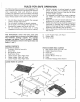
CONTENTS OF HARDWARE PACKAGE: (Figure tL Sweeper Housing AssembLy Hitch Pin A (I) B (2) Spacers 1" Dia, x 3/4" Long C (1) Hairpin Cotter D (2) Hex Bolts 3/8"16 x 3/4" Long E (2) Hex Bolts 3/8q6 x 1-1/4" Long F (2) Flat Washers 3/8" I,D G (8) Hex Lock Nuts 3/8-16 Thread H (t) Hex Bolts 3/8-16 x 1-1/2" Long t (1) Flat Washer 17/32" x t-t/2 x t0 Ga J (2) Flat Washer 5/16" I,D, K (3) Hex Bolts 3/8-16 x t" Long L (2) Carriage Bolt 5/16-18 x 3/4" Long M (t) Spacer 13/32 I.
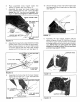
ASSEMBLY TOOLS (1) (I) (1) (1) (1) (1) (t) 0NSTRUCTIONS TOP VIEW REQUIRED 3/8" x 1" HEX BOLT (FRONT HOLE) Adjustable Wrench 3/8" Open End or Box Wrench 7/16" Open End or Box Wrench 1/2" Open End or Box Wrench 9/t6" Open End or Box Wrench Standard Screwdriver Pair of Pliers HITCH BRACKET POSITION SEE GROUP "B" PAGE 10, HITCH Refer to carton contents figure on page 2 and figure I on page 3 for parts and hardware needed to assemble sweeper housing,, BAR 3t8'" HEX LOC!( NUT Assemble the hitch bar to t
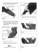
Assemble other end of height adjustment strap to height adjustment handle See figure 7. Place slot on strap in line with square hole in height ad}ustment handle Secure strap with 5/16" x 3/4" carriage bolt, 5/16" flat washer and hand knob See figure 7. NOTE: Lightly coat slot with grease for ease of adjustment. , BAG MOUNT \ 318'" x 314" HEX BOLT Assemble the grip, with finger knobs as shown, to the height adjustment handle, See figure 7, , x 1-1t4" HEX BOLT , Assemble the hitch pin, two 1" Diao x 3/
ASSEMBLY Slide the two upper hopper tubes together, as shown in figure 11. Line up the center holes, OF HOPPER BAG Refer to carton contents figure on page 2 and figure 2 on page 3 for hardware needed to assemble hopper bag. See page 2 to identify both upper and lower hopper tubes.
6_ 7_ 10, Place assembled lower hopper tubes into bottom of hopper bag, See figure !4. Assemble the upper and lower hopper tube ends together with two 318" x 3/4" hex bolts (inside} and 3t8" hex lock nuts (outside), See figure 14. Do not overtighten to allow for pivot, UPPER HOPPER Secure the bag corners over lower hopper tube by snapping the flap to bag bottom on each side, See figure t7.
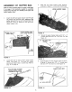
12o Locate hole along side of upper hopper tubes and pierce a hole through the bag aligned with the hole in the tube, See figure 20. CLEVIS BAG RETAINER UPPER HOPPER TUBE / PIN FIGURE 22 16 Secure hopper 24_ FIGURE 20 13. Assemble mount clamps to each side of upper hopper tube.
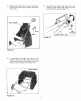
17. Assemblethe wind screento upperhoppertube, Pullthe four cornerloopsandsnap,Seefigures 25 and 26, 19. To remove the hopper bag frame from the sweeper,simplyflip the bag retainersupward and removethe bag°See figure 27. UPPER HOPPER TUBE BAG RETAINER OOP SNAP HOPPER FIGURE 27 FIGURE 25 18. To assemble the hopper bag frame to the sweeper, simply hook the clevis pins into the notches in mount arms, Bag retainers must pivot freely to lock in position., See figure 26.
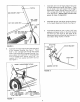
A BRUSH HEIGHT ADJUSTMENT APPROXIMATELY CENTERED IMPORTANT TO ASSURE BEST PERFORMANCE OF YOUR NEW SWEEPER, THE FOLLOWING INSTRUCTIONS MUST BE READ CAREFULLY. SEE FIGURE 28. YOU MUST SET UP SWEEPER TO THE TOWING VEHICLE, SO BOTTOM OF BAG FRAME IS APPROXIMATELY LEVEL ON FLAT SURFACE, SUCH AS DRIVE OR WALK.
OPERATION B_ Your sweeper is a precision piece of equipment. Engineering skill and experience have been combined to provide reasonable safety and efficiency. However, as with any type of mechanical equipment, carelessness or error on the part of the operator can result in damage to your equipment. Therefore, exercise care at all times and do not subject your sweeper to misuse. SWEEPING Do Not drive or dump the sweeper too close to a fire as the brushes and bag can be destroyed by excessive heat or flame.
BRUSH REPLACEMENT WHEEL GEARS/PAWL SERVICE 1, 2, To service wheel gears, Do Not Remove both wheels at the same time. Remove one wheel 1. Remove the hopper bag from 2. at a time to prevent use of left hand parts on right hand side, When removing gears make notes on position of all washers and snap rings, 3, Brush replacement should be done one brush at a time, Tip the sweeper back on housing for ease of brush replacement° Do not remove hex bolts from double brush retainers through brush shaft.
NOTES 13
REPAaR PARTS FOR MODEL 488.240320 32" LAWN SWEEPER 18 36 ! 40 23 2O 67 67 5 46 69 14 / J/61516_ 27 \ 14 _,,/.
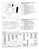
REPAIR PARTS LIST FOR MODEL 486°240320 NQ PART QTY 1 2 43903 43886 4 1 3 4 5 6 7 8 9 10 11 12 t3 14 15 16 43885 43645 43720 23387 43979 43928 43927 43930 43929 43956 C-9M5732 43655 1650-21 44007 1 I 1 1 1 1 1 1 1 t 8 2 4 4 17 43182 4 !8 43407 2 19 44008 2 20 44137 4 21 22 43081 0142-000 2 2 23 24 25 43064 43661 43013 2 4 12 26 1095 4 27 28 29 43081 43064 43080 2 I 1 30 31 32 33 34 35 36 23400 43957 1652-13 1629-56 62445 43900 43012 I 1 2 2 1 2 8 37 62501 1 38 39 40 41
32'" CRAFTSMAN LAWNSWEEPER Always mention the Model Number when or repair parts for your Lawnsweeper.