
Owners manual


4
ASSEMBLY
FEATURES & OPERATION
Assembly
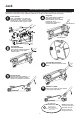
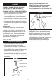
Handle Assembly
• Refer to Picture 1 when performing this step.
Align Quick Disconnect pushpin in upper
handle piece with attachment hole in lower
handle piece. Push upper piece into lower
piece until pushpin pops through hole.
• Suciently loosen the Handle Socket Screw
to insert the assembled handle (Picture 2).
• Line up the square shaped hole located at
the bottom of the handle over the square
bolt inside the Handle Socket.
• Lower the handle onto the bolt. Secure the
handle in place by tightening the Handle
Socket Screw until the handle stops rotating.
NOTICE: ONLY use the handle provided
with this jack. Handle is specially designed
to properly t into handle socket and engage
release valve.
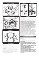
Operation
Raising the Jack
• Place vehicle in park, with emergency brake
on and wheels securely chocked to ensure
lifting stability.
• Refer to the vehicle manufacturer owner’s
manual to locate the approved vehicle lifting
points.
• Position the jack so that the saddle will rmly
contact the vehicle lifting point.
• Close the release valve by turning the
handle clockwise until it stops.
• Pump jack handle until saddle nears contact
with vehicle lifting point. Check to see that
the saddle is centered and will contact lifting
point rmly.
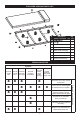
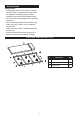
Oil Fill
Screw
Pin
Pump Plunger
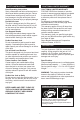
PREPARATION
Preparation
After rst removing from shipping box
• Carefully remove the retaining clip from the
back of the service jack.
CAUTION: The socket will tend to spring
upward when the clip is removed. To prevent
possible injury, place one hand on top of
socket to control its upward motion when
removing clip with other hand.