o_vne 1 Model No. 502.255193 , ,i i iil,ii 12 HP. LECTRIC START 40" MOWER SPEED LAWN TRACTOR CAUTION: Read And Follow All Safety Rules And Instructions Operating This Equipment. Before ® Assembly o Operation e Maintenance e Service ® Repair F-91726 12-01-90 and Adjustment Parts Sears, Roebuck and Co, Chicago, IL 60684 UoS.A.
SAFETY Safe Operation As Recommended RULES Practices by American for Riding National Vehicles Standards Institute This cutting machine is capable of amputating hands and feet and throwing objects. Failure to observe safety instructions could result in serious injury or death to the operator or bystanders.
SAFETY RULES - continued SLOPE OPERATION: Slopes and rough terrain are major factors related to loss of control and tip over accidents which can result in severe injury or death. All slopes require extra caution. If you cannot back up the slope or if you feet uneasy on the slope, do not mow ito See the "Slope Guide" in the back of this book to check for safe operation, DO 1. Mow up and down 2o Remove slopes, not across. 3 Watch 4. Use slow 5,, Follow 6. Use extra 7.
Congratulations on your purchase of a Sears Tractor. designed, engineered and manufactured ible dependability and performance. to give you the best poss- If you experience any problem you cannot see your nearest Sears Service Department. well trained this unit. technicians and the proper Please read and retain this manual. to assemble and maintain "Safety Rules".
i i TABLE OF CONTENTS SAFETY RULES ............................................... 2-3 CUSTOMER RESPONSIBILITIES ......................... 4 PRODUCT SPECIFICATIONS ............................... 4 WARRANTY ...................................................... 4 TABLE OF CONTENTS ....................................... 5 INDEX ............................................................... 5 TRACTOR ATTACHMENTS ................................ 6 ASSEMBLY ................................................
ii TRACTOR Attachments That illl iiiiiillllllllllll ATTACH Add Craftsman to the Lawn M ENTS Usefulness of Your Tractor Sears offers a wide variety of attachments that fit your iawn tractor Many of these are listed below with brief explanations of how they can help you°This list was current at the time of publication; however, it may change in future years- more attachments may be added, changes may be made in these attachments, or some may no longer be available_ Most of these attachments do not
ASSEMBLY i ,,,,,,, ,u ,,,,,,,,, i,,, u ...................
ASSEMBLY ii HOW TO PREPARE AND CHARGE THE BATTERY ii Remove and discard NOTE; Before you install the battery, add the battery acid the meta_ (Electrolyte) and charge the battery° Battery acid will damage paint and parts, WARNING: Vent Cap Read the instructions included with the battery acid container. Protect your hands _ 1. nd eyes fromyou.
ASSEMBLY _OW TO ASSEMBLE rilE STEERRNG WHEEL Jse the fasteners shown below to install ;asteners are shown at full size the steering wheeE The @ S1eedng B ix66 B t 5×90 Bellows 1 Make sure the front wheels point forward. Slide the bellows over the steering post. Make sure the collar of the bellows on top. Push on the top of the bellows.
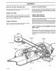
= == =l= H =l=l,====,l,l,l,l,l==l,l=ll=l=== ASSEMBLY = 111i= iH ,lliHi,i,ll HOW TO ATTACH CHECK THE DRIVE THE HUB CAPS BRAKE The drive brake can be easily checked as foHows_ Set the parking brake Move the shift lever to the neutral (N) position Push the unit. Push each hub cap onto the center' hub of each wheel, Make sure the washer holds the hub cap in place_ If the rear wheels rotate, adjust the drive brake.
iMPORTANT: Remove and identify the contents CONTENTS of each box as shown OF BOX below: A Containers Weight Bracket Hin_ Frame Mount Bracket _L=_ CONTENTS OF BOX B Window Parts Bag (In paper bag_ Extension Tube and Plate Assembly Fr°ntWi_" (2) Plastic Bags (Not shown) \ Channel Elbow D-81_8 F_91726 I 1
PARTS BAG - conterlts for Grass Bagger The fasteners and other loose parts are shown below. The fasteners are shown full size with the quantities NOTE: Some of the fasteners will not be required for your modoLi_., in brackets (). ..,..
ASSEMBLY HOW TO ASSEMBLE Assemble the front weight THE FRONT support with WEIGHT the fasteners shown full size below, © 1, (B) (A) (c) 15x 109 2x74 15x88 Assemble the tractor the four carriage as shown,, bolts C_ .
iii iiiiiii1,,111 ASSEMBLY H =l= =H,N :::::::::::::::::::::::::::::::: HOW TO MOUNT THE FRAME ASSEMBLY Remove and discard the two self=tapping screws from the rear of the framer Use these two holes to mount the frame bracket_ 2.
From the right side of the unit, install 6, the channel channe_ Mount 7_ as shown, Rotate the channel the channel pin throug (F) h pin to lock the in place, the outer tube to the channel as shown, Make sure the holes on one end of the outer tube are on the right side of the unit, Use the fasteners fasteners shown full size below Make sure the (G) are tight_ CAUTION: If the fasteners are tightened outer tube can be damaged.
IIIHII=I=IIIll i= i ASSEMBLY HOW 1o TO MOUNT Assemble THE COVER the hinge to the cover with the fasteners full size below,.
................................ i,, ,lui un,lllli,l_Jii ASSEMBLY HOW 1,, TO MOUNT Assembfe latch fasteners shown THE EXTENSION pin (A) to the TUBE extension tube with the below A 54563 15x89 2x39 A B C 2, Move the lift lever to the highest cut position, 3. Disconnect the wire to the spark plug. Raise the deflector, Rotate the blade away from the discharge openir;g, Remove the carriage shown.
ASSEMBLY HOW TO MOUNT THE CONNECTOR Mount the connector TUBE tube with the fasteners shown full size 1 below,, Assemble the handle tube the fasteners with screwdriver 15x89 and tighten the 3, Fasten the elbow 4x24 4, 5_ cover, (E) the in the hole of cover NOTE: To help the elbow with the hole in the tube with the self=tapping screw until the head of the put wax or polish efbow 7 rubber latch is aligned whh Slide the bottom end of tube and you open or close the on
ASSEMBLY HOW TO ASSEMBLE THE CONTAINERS NOTE: There is only one way that these containers can be put together. Carefully read and follow the instructions below_, 1 Separate the six container have 2 tops, 2 middle 2, Look for a number numbers 3. into two on one side groups pieces of each You will top piece The for the two top pieces are I arid 3.
ASSEMBLY i HOW 1 TO ATTACH Tilt the seat forward Two 3,.
i , , OPERATION KNOW THE PRODUCT Before you operate the unit, read this instruction When you read this instruction follow the operating Position book° If you understand book, compare instructions the illustrations and the safety rules the unit and how the unit operates, to the unit. Learn the location Keep this instruction book for future you will get the best performance. of the controls.
OPERATBON The operation foreign thrown result in severe safety glasses your lawn eye the spectacles available at Sears TO USE THE can result eyes, damage° shields and Wide over the mower in the or eye mower recommend HOW of any lawn objects Retail wear Safety Completely for 3, Remove your t from release the paddng will hold the unit, I To release the clutch/brake automatically parking FUNCTION pedal and brake, completely The brake Trimming Snow the control
OPEBATnON i HOW TO USE THE THROTTLE Use the throttle control engine_ 1 To start a cold CHOKE 2, The to increase engine, position lever HOW TO OPERATE WITH THE MOWER HOUSING the speed of tile to the For transport throttle with a detent, using a grass bagger, For maximum also for a cooler FAST position, The the is marked and when the FAST position 4,, CONTROL or decrease move , START WARNING: The deflector is a safety device,, Do not remove the deflector° The deflector forces th
HOW TO USE THE GRASS BAGGER WARNING: Do not ride up or down slopes that are too steep to back straight up. Never tide the unit across a slope.. See the "Slope Guide" in the back of this book for information on how to check slopes.. To operate the unit with the grass bagger, control follow 1, Put the throttte 2, Put the shift lever in FIRST (1) position 3, If the height of the grass is more move the mower grass.. Lower' cutting than 3-1/2 to the highest the mower width I the steps below.
OPERATRON BEFORE STARTING THE ENGINE HOW TO START WARNING: The electrical system has an operator presence system that includes a sensor switch mounted in the seat. These components tell the electrical system if the operator is sitting on the seat° For your protection, always make sure this system operates correctly. This system will stop the engine when the operator leaves the seat if the blade engagement control is engaged. CHECK OIL - Add as needed NOTE; runs. Do 1, Make 2.
OPERATION OPERATING 1. 2, TIPS Check the blade engagement control For the blade(s) be correct correctly, to disengage for correct adjustment.
MAINTENANCE Blade, Inspect FIRST 2 HOURS EACH USE PROCEDURE SCHEDULE EVERY 25 HOURS B!ade Engagement _ Brake, T Clutch, O Shift Control, Check X Check X Lever, Check X Tires, Check Check & Char_3e _ Battery, Ctean Lubrication 1 Coolin 9 System, i_ Oil, Chan£1e Air Filter, Muffler, X , Clean ......... Fuel Filter, RECOMMENDATIONS 1.
MAINTENANCE _NSPECT BLADE WARNING: Before you inspect or remove the blade, disconnect the wire to the spark plug, If the blade hits an object, stop the engine° Check the unit for damage The blade has sharp edges,. When you hold the blade, use gloves or cloth material to protect your hands,.
MAUNTENANCE HOW TO CHECK AND ADJUST THE BLADE ENGAGEMENT CONTROL WARNING: engagement 1 Stop 2 Before you adjust the blade engagement control lever, check and level the mower housing. See "How To Level The 3 4 5.. the engine.. Completely To prevent an injury, the blade control must operate correctly.. Disconnect the wire from the spark Engaged Position pEug.. Mower Housing" Set the height of the mower housing in the lowest position. Move the blade engagement control to the ENGAGE position..
MAnNTENANCE HOW TO CHECK AND THE DRIVE BRAKE ADJUST Completely pedal forward,, brake push the clutch/brake Movethe If the rear wheels the drive brake rotate, adjust Push the unlt.
5AAtNTENANCE HOW TO ADJUST NOTE: To help show in the illustration, t.
MAINTENANCE _JL_L_ BATTERY CUT AWAY To charge as follows or clean the battery, remove the battery from VIEW Vent the unit Correct WARNING: To prevent sparks, disconnect the black battery cable from the negative (--) terminal before you disconnect the red cable.. Liquid Level WARNING: The battery contains sulphuric acid which is harmful to the skin, eyes and clothing.
MAINTENANCE i ii Hi ,ll ill lllil liiNil i i = = IENGONE HOW TO CHECK THE OIL NOTE: Do not check the le;vel of the oil while the engine runs. 1. Make sure the unit is level. 2_ Clean the area around the dipstick, Remove the dipstick_ Wipe the oil from the dipstick° Insert the dipstick into the oil fill tube. Turn the dipstick clockwise until it is tight, Remove the dipstick. Check the oil level on the dlpstick.
MAgNTENANCE ,=,,,J, iLiJ ,,, HOW TO CLEAN Some engines N H ii iHi ii ii = THE AIR FILTERS have two filters, an outer foam filter around paper filter. Clean the air filters every 50 hours.
HOW TO ADJUST The factory settings THE CARBURETOR for the carburetor the engine is operated under adjust the carburetor mixture. are for most conditions, the following 1o The engine 2. A change has a loss of power 3. A 40 ° change 4, was adjusted at 80 ° at the factory The engine is operated above 4,000 from if an adjustment 1., summer is needed, Turn the needle follow operation temperature.
SERVICE AND ADJUSTMENT .,I,,,,,,,,,UUl1' J HOW TO REMOVE 1- Move 2_ Move the DISENGAGE 3- the hair pins and Remove 7,. Remove the mower & Pull the unit,, mower 1. 2_ lever to 4. the from hanger from TO INSTALL the stack pulley the suspension 6. Attach "A" from the axle support._ from rod. 7, side See Attach the right and,the plate to the lifter and hair pins, ! 0,. Push the mower housing under the right side of the unit.
SERVICE AND ADJUSTMENT HOW TO REPLACE MOWER 1 DRIVE Remove 2, 4, away from the idler pulley on "How away from remove the mower drive belt, Remove the mower drive belt from NOTE: Replace the Put the belt around 8, Make sure the "V" side of the mower and remove mandrel mower the right drive the left mandrel belt with drive belt, Pull the belt retainer pulley° Put the beh around away from the idler putley, the drive belt is under the end of the cross Make sure the mower 11
SERVICE AND ADJUSTMENT HOW 70 REPLACE THE MOTION DRRVE BELT Motion 1• Remove the mower To Remove 2o Completely parking housing, The Mower push See the instructions Housing" the in this pedal forward on "How instruction and book engage Drive the brake, Loosen The" Belt Guides 3o Remove the idler pulley 4o Loosen 5o Remove the bett from the drive pulley 6, Remove the two screws the belt guides Remove the support 7o Disconnect 8o Remove Pulte, that are arqund the dri
SERVICE HOW TO LEVEL THE MOWER If the mower housing lawn will look better. is level, WARNING: adjustment, wlre 1, Make 2 Check spark wilt cut easier plug_ Remove prevent the air pressure the mower the engine Move the the and the spark from position height There are two the mower tires.
SERVnCE AND ADJUSTMENT HOW TO REPLACE THE LIGHT 1, Raise the tractor 2. Pull the tight socket 3 Pull the light bulb from the socket 4 Install Push the socket HOW a new hood, light from bulb TO CLEAN the bezel. into the bezel. THE MOWER HOUSING stop the engine and disconnect the wire to the WARNING: Before you clean the mower housing. spark plug. _ Grass and other debris 0n top of the mower belt,from 1, BULB working Move correctly.
SERVICE HOW Ifthe TO START batter,/is WITH A WEAK too weak to start the engine, BATTERY the battery charged If ",Jumper Cables" are used to start emergency, follow the procedure below, NOTE: The unit system. ground is equipped Also, the other system° with vehicle WARNING: a 12 volt must 1 Put a wet Connect 4, cloth 5.
TROUBLE SHOOTING (Recoil-Start PROBLEM: The engine 1. 2 3 the steps, How To Start The Engine in this book. the battery terminals Tighten the cables for a loose wire_ Tighten the limit switches. (See tire diagram..) the fuel tank. Clean the fuel tineo Replace the fuel Follow Clean Check wiring Drain filter 4. will And not start. Models) PROBLEM: A hot engine 1.. Clean the air screen 2.. Check the oil 3 4. Remove the spark plug(s} Move the throttle to the SLOW 6..
MODEL NO. 502.255193 ELECTRICAL SCHEMATIC BATTERY BLACK RED + 12V RED SOLENOID t r t I I I FUSE I _/ -- 15 AMP STARTER ,, |I BLACK SEAT SWITCH (SEAT UNOCCUPIED RED IGNITION [ CLUTCH INTERLOCK ATTACHMENT PEDAL SWITCH INTERLOCK SWITCH BLAcK(CLUTCHo_ENGAGED)o BLACK (DISENGAGED)!_,r - _ -_ BLK. BLK. B YELLOW L ;L__O_4YELLOW _ ,_ N EC-_--R YLW. N'C i"_0N (CLOSED IF UNPLUGGED SOLID STATE IGNITION YELLOW? _ SPARK PLUG FROM0 SEAT @- SWITCH) YELLOW HEADLIGHT 2.
MODEL NO. 502.
MODEL NO. KEY NO. REPAIR PARTS CHASSIS & HOOD 502.255193 DESCRIPTION 1 Seat 2 Plate Assembly, Switch PART KEY NO. NO. DESCRIPTION PART MFG.
MODEL NO. 502.255193 1 REPAIR MOTION PARTS DRmVE 2 8 16 I_5701 5 58 •14 17 oJ 22 21 25 19 32 31 3O 27 29 5 28 53 45 51 59\ 57 F-91726 54 46
MODEL NO. KEY NO, DESCRIPTION REPAaR PARTS _,qOTnON DRDVE 502.255393 PART NO, IVlFG. NO.
MODEL NO, 502.255193 REPAIR PARTS STEERING D-5699-3 0 10 I 27 29 25 22 1 24 38 \ 30 F=91726 29 28 4.
MODEL NO. REPAmR PARTS STEERaNG 502.255193 KEY NO. * When you order F-91726 Steering MFG. NO.
MODEL NO. 502.255193 REPAIR PARTS MOWER SUSPENSION D-5698 3 / 6 13 / 11 \ 10 o \ \ 18 12 21 15 22 _% / 13 26 \ 3o 27 F-91726 ! 13 50 k t3 20
MODEL F_91726 NO. REPAIR PARTS MOWER SUSPENSION 502.255193 KEY PART iViFG. NO. DESCRIPTION NO. NO.
MODEL NO. 502.
MODEL NO. REPAIR PARTS MOWER HOUSING 502.255193 PART NO. KEY NO. DESCRIPTION iVIFG, NO. KEY NO. DESCRIPTION PART NO. NIFG. NO. 1 Nut, Hex 15xlO1 3I Guide, Belt 9t797E700 2 LOckwasher 18x33 32 Bracket Assy.
MODEL NO. REPAIR 502.255193 o D-5749 N3_19 ILl I- \ oo 731 G3_ M07731 03 M3V7'8 I" F-91726 54 PARTS WiRiNG
MODEL NO. REPAIR 502.255193 II1 E _o _ 03 _.0 03 03 t.
_ODEL NO. REPAIR PARTS ENGINE MOUNT 502.
MODEL NO. 502.255193 REPAIR PARTS ENGINE MOUNT KEY NOo 1 Fuel Cap 55988 2 Fuel Tank 91869 3 Hose Clamp 91174 4 Fuel Line 92160 5 Hose Clamp 23713 6 Screw 26x214 7 Screw STD610803 8 Throttle 9 Engine Briggs & Stratton Model: Control NIFG. NO.
MODEL NO. REPAIR PARTS GRASS BAGGER 502.
MODEL NO. 502.255193 REPAIR PARTS GRASS BAGGER KEY NO. DESCRIPTION PART NO.
MODEL NO, REPAIR 502.255193 SiX SPEED _.PEERLESS MODEL PARTS TRANSAXLE NO.
MODEL NO. 502.255193 REPAIR PEERLESS KEY NO. PARTS SIX SPEED TRANSAXLE MODEL NO. 930-011 PART NO. KEY NO.
ENGINE BRIGGS PARTS iLLUSTRATION & STRA'R'ON - MODEL 12 HP. 281707-O428-O1 _ _353 520 _)354 305 66,3 232 _1564 307 _5 230 634A ,___._62 1I 757 ]1019lABEl.KITI 1021 1020 [___58 GAs_ETI 74] SET 219 46 36 26 524 *SPECIAL TOOLS TO INSTALL,.
ENGINE BRIGGS PARTS ILLUSTRATION & STRATTON - MODEL 12 HP.
ENGINE BRIGGS PARTS iLLUSTRATiON & STRATTON - MODEL 12 HP. 281707-0428-01 310 i 513 896 F Housing _=== O__ Length --_ 803 801 NOTE: To identify Briggs & Stratton manufactured starter motors, measure the housing length,. Assemblies F-91726 include all parts shown 64 in frames.
ENGINE PARTS LIST BRIGGS & STRATFON 12 HP. - MODEL 281707-0428-01 DESCRIPTION MFG. PART NO. 1 Cylinder Assembly 490450 2 Bearing, Cylinder 399265 KEY NO. NOTE: Requires for instatlation_ special MFG. PART NO.
ENGINE BRIGGS PARTS LIST & STRATTON 12 HP. - MODEL 281707-0428-01 DESCRIPTION IV1FG. PART NO, KEY NO. DESCRIPTION 219 222 Oil Slinger, Gov. Gear & Bkt. Plate -Governor Control 490815 491594 544 549 Armature Assembly Washer -Air Cleaner 390837 224 Screw -Air Cleaner 94018 552 231597 225 Crank -Governor 231058 562 Bushing -Governor Crank Bolt -Governor Lever' 227 230 Lever Assy Governor Washer =Governor Crank 490927 222450 592 601 Nut -Hex.
"4 0 O o , ; : g 4) e 0 e 0 e el : 0 : a g e 0 O 0 e_ r=, 0 m I m F-91726 67
® 2 HP. ELECTRIC 40" MOWER 6 SPEED LAWN TRACTOR The Model frame. Number The Model for the mower Number is found for the engine spark plug. Always give the Model parts for your unit.