® 32.8 cc 2-cycle 10 inch Diameter Tines MiNi TILLER/CULTIVATOR MODEL NO. 536.797501 Caution: Read and follow all Safety Rules and Operating Instructions before first use of this product. SEARS, ROEBUCK 339426 03/07/96 AND CO., Hoffman Estates 60179 U.S.A.
Table of Contents Warranty Safety Rules Contents of Shipping Carton Assembly Operation Maintenance 2 2 2-3 4 4-6 7-10 t1-12 Service and Adjustments Storage Troubleshooting Edger Repair Parts Engine Repair Parts Spanish (EspaSol) Parts Ordering/Service.
with fuel in the tank inside a building where fumes may reach an open flame. SAFE STORAGE • Always refer to the owner's manual instructions for important details if the mini tillertcultivator is to be stored for an extended period. • Never store the mini tillerlcultivator with fuel in the fuel tank inside a building where ignition sources are present such as water and space heaters, clothes dryers, and the like.
in the state of California the spark attester is required by law (Section 4442 of the CafifoP nia Public Resources Code), Other states may have similar laws, Federat laws apply on federal lands. A sparkarrester/muffler is availablethroughyournearestSears AuthorizedServiceCenter(See REPAIR PARTS section inthismanual), Contents of Parts Bag (shown full size) 1 - Tie Strap 1 - 10-16 x 1-1/2Inch Washer Head TapScrew Parts packed separately In carton (not shown full size) •Lett Lower Handle 1 - 5.
TO REMOVE CULTIVATOR MINI TILLER/ FROM CARTON • Remove the plastic parts bag from the carton. • Remove the handles from the carton. - Remove packing insert from carton° * Lift the mini tillerlcultivator out of the _arton and place on a hard level surface. . Remove packing material from around tines.
Finger tighten only. ° Using two 7/16 inch wrenches, tighten the Iocknuts on the screws in the lower ends of the lower handles just enough to hold the lower handles firmly in place / IMPORTANt; Overtighteningthe screws enough to changethe shapeof the handlescan resultin damageto the enginecasting. / • Hold the curved head carriage bolt against the outside of the lower handle while tightening the tee knobs securely.
KNOW YOUR MINI TILLER/CULTIVATOR READ THIS OWNER'SMANUAL AND SAFETYRULESBEFOREOPERATINGYOUR MINI TILLER/CULTIVATOR,Comparethe illustrations withyourminitiller!cultivator to fa_ miiiarize yourseffwiththe location of variouscontrolsand adjustments.
HOW TO USE YOUR TILLER/ CULTIVATOR .A /_ WARNING: The operation of this mini tiller/cultivatorcan result in foreign objects being thrown into the eyes, which can cause severe eye damage. Always wear safety glasses or eye shields while operat* ing the mini tiller/cultivator. We recommend standard safety glasses or Wide Vision Safety Mask for over your glasses. TO STOP MINI TILLER]CULTIVATOR • Release the throttle control to stop the tines. • Move the shut-off switch on the engine to the OFF position.
gine while in storage° To avoid engine problems, the fuel system should be emptied before storage for 30 days or Ionger. Drain the gas tank, startthe engine and let it run until the fuel lines and carburetor are empty. Use fresh fuel next season. See Storage Instructions for additional information, Never use engine or carburetor cleaner products in the fuel tank or permanent damage may occur. GASOUNE AND OIL MIXTURE Mix gasoline and oi! 24:1 as follows: - Pour 1 U.S.
- If the engine becomes flooded, see the Spark Plug Maintenance paragraph in the Malntenanc_ section of this manual Then pull the starter rope with the choke lever in the NO CHOKE position. WEED REMOVAL CAUTION: The muffler and sur.. rounding areas become hot after running the engine_ Avoid these areas, TILLING HINTS • When using the mint tiller/cultivatorto remove weeds, it is best to till no deeper than t-1/2 Inches° Tilling deeper will only pull to the surface ungerminated weed seeds.
CUSTOMER RESPONSIBILITIES SCHEDULE SERVICE RECORDS Fill in dates as you complete regular service T{gh_nAll Screws and Nuts SERVICE DATES ii Before After Each first2 _=ry Every 75 Uso Houm Hours Hours p4 Before SloragoIBefore Each S_son v_ Lubflcale Ttne Sha|t tf C_ r Lubr{cate Transmission S_k Rug Cie__d R_-Oii Aircie_ei Fiiiei v' v" v" ioy!!o.o, ,, ,,,, ..... Drain Fue! GENERAL RECOMMENDATIONS • Reinstall the air vent screw.
ENGINE to enter the engine. - Reassemble the filter. Place the cover on the air cleaner housing and tighten screws to secure cover to the housing. a_rc CAUNON: Never run engine without leaner element installed. A defective air cleaner can result in loss of engine power and cause excessive wear or damage to engine components if dirt or dust is permitted to enter the engine through the carburetor° An air cleaner that is clogged with dust or dirt should be cleaned and re-oiled.
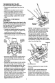
Properly installed Right Side_nes TINE REPLACEMENT The mini tillerlcultivator is left hand or right hand as viewed from the operator's position behind the unit. All four tines on this unit are different and cannot be interchanged..The tines must be properly installed as shown in figures to the right or the mini tiller/cultivator will not function properly,, For working close around plants or in small areas, the OLrlsidetines may be removed to reduce the tilling width to about 7 inches.
• Turn the mixture adjusting screw slowly clockwise until the engine falters, Note this location. - Turn the mixture adjusting screw slowly counterclockwise untilthe engine starts to sputter. Note this location. • Turn the mixture adjusting screw clockwise until it is halfway between the first position where the engine faltered and the second position where the engine started to sputter. .
ENGINE Start and run the engine until it stops due to lack of fuel Pull the starter handle slowly until you feel resistance due to compression pressure, then stop, Release the starter tension slowty to prevent the engine from reversing due to compression pressure_ This position wilt close both the intake and exhaust ports to prevent corrosion of the piston and cyl;nder bore, IMPORTAWI': It is important to prevent gum deposits from forming in essential fuel system parts such as the carburetor, fuel filter,
CRAFTSMAN 10" - 1.6 H.P. TILLER/CULTIVATOR 536.797501 ENGINE ASSEMBLY NO. PART NO. 10 ENGINE 11 12 13 14 17 PART NAME Tecumseh 1°6 hp 143961672 (See Engine pages) Flatwasher, 378x1,25x,06 Ht Rotor Washer, Regsptik ,263x49x.O'_ Screw, 1/4=20xt _75 C_ble, Throttle Owner's Manual 335350 t2o3eo 1_o42 3!93o6 339426 323392B All unnumbered Items are Interchangeable with opposite slde Note: Nways use original equipment parts.
CRAFTSMAN 10"-t.6 H.P. TILLER/CULTIVATOR 536.797501 TINE SHIELD ASSEMBLY REF, NO. PART NO. 48O i309073_633 48I 273869 482 120392 483 1502 490 56158 491 56157-853 REF. NQ, PART NO, PART NAME 492 156155-853i "Fine,Assy Outer LH 493 i56!53-853 ! "Fine, Assy Inner RH i494 56154-853 _ne, Assy Outer RH 495 56123 Clevis Pin .3tx1..38 496 56180 Hair Pin 091DiaxI 62Lg f PART NAME Tins Shield i Screw, 1/4-20x5 00 Flatwasher .281x 63x.
CRAFTSMAN 10"- 1,6 H.P. TILLER/CULTIVATOR 536.797501 DECALS _PART @ NO. 822 | 823 ]320711 824 1338985 _305828 DETHATCHER DEBRIS (REF)_ PART NAME Reference Only Decal, Caulk;on Decal, "line Sears Mini-Til Decal, Caution (Starting Inst) 320229B CULTIVATOR SHIELD HANDLE ASSEMBLY REF. NO. §30 932 934 941 942 943 944 945 946 947 _48 REF. ITEM THROTTLE_NT_OL PART NO .... PART NAME 56237-853 Upper Handle 339398-85,3 Lower Handle, LH 339399-853 Lower Handle, RH 56199 Cart. Bolt, 5/16_18x1.
CRAFTSMAN 10" - 1.6 H.P. TILLER/CULTIVATOR 536.797501 TRANSMISSIONBREAKDOWN REFo NO. PART NO.
CRAFTSMAN 2-CYCLE ENGINE MODEL NUMBER: 143.
CRAFTSMAN 2-CYCLE ENGINE MODEL NUMBER: 143.961672 REF, REF, NO. PART NO, 1 250302A 650888 13 13A 166 160 19 20 30 39 270288A 1270298 490324 650986 PART NAME Cylinder (lncl 1190184,167&t87A Screw, Torx %30, 4-20 x 43/64" Crankcase Ass'y. (incl. 20 & 44) Crankcase Cover Ass'y Air Vane Governor Spring Oil Seal Crankshaft 310286A 310271 530163 510348 530110 510319 Piston & Rod Ass'y. (Ind.
CRAFTSMAN Carburetor 2-CYCLE ENGINE MODEL NUMBER: 143.961672 No,. 632941B PAR t NO. i NO. 40A 632953 6329to 45 632902 48 5O 632904 NO+ | PART NAME 632941B _ Carburetor I (Incl t84 of Engine Parts List} 632947 _ Throttle Shaft & Lever Ass'y 632928 I "l'hrottle Relum Spring 6.
CRAFTSMAN 2-CYCLE ENGINE MODEL NUMBER: Starter No, 590690 12 13 \ REFPART PART NAME NO.
MINI ZURCADORA/CU LTIVADORA Contenido 24 Garant_a 24 Reglas de Seguridad 24-26 Contenido la bolsa con las partes 26 Montajff 27-29 Opera clon 29-33 Maintiemento 33-35 Servicio Y A_ustes 36-37 Almacenamlento 37-38 Identificacton de Problemas 39 Partes de Repuesto 16-19 Partes de Motor 20-23 Orden de Partes Servicio Contratapa GARANTIA LIMITADA DE UN AiSle DE LA MINI ZURCADORA/CULTIVADORA CRAFTSMAN Durante un a_o a partir de ta fecha de compra, siemprey cuando esta Mini zurcadora/ cuh|vadora Craftsman sea
• Liana et estanque de combustibFe afuera con touche cuidadoo Nunca liana el estanque de combustible en recintos cerrados. Vuelva a colocar la tapa del estanque de combustible en forma segura y limpie el combustible derramado_ cuttivadora sin buena visibilidad o luzo . Nunca remueva la tapa del estanque de combustibte o agregue combustible a un motor qua est,. funclonando o qua est& caliente. .
dedestaponar los brazes de cultivo y bosques, de arbustos o de c_sped, a menos qua el sistema de escape del motor venga equipado con un amortiguador de chtspas que cumpla con las leyes locales o estatales (si existen).. Si se usa un amortiguador de chtspas, el eperador debe mantenerlo en condiclones de trabajo eflcientes. cuando hags repataciones, ajustes o inspecciones..
,_ PRECAUCION: Siempre use anteojos de seguridad o pmtecciones pare los ojos al montar la mini zurcadora.,' cu]livadora. HERRAMIENTAS NECESARIAS PARA EL MONTAJE PARA INSTALAR DEL MANGO EL CONJUNTO Los mangos inferiores tienen una dobladura corta en el exlremo inferior y son pianos en la parte superior, pare permitir qua el mango superior se coloque entre los mangos inferiores° Para montar los mangos haga Io siguiente: .
AVISO: Para permitir el montaje adecuado de la secct6n plane del mango superior aseg_rese qua la secci6n plane de los mangos infer_oresest6n mirando hacia adentro, AsegOrese que haya una arandela en cada tornilio de montaje vea figure abajoo Puede qua sea necesario rotarel mango inferior pare alinear los agujeros de montaje. \_\ \_ en su lugar.
AVISO: Un lade de la correa de ligadura es _spero, y el otto es tiSOoE! lade ,tspero ttene que quedar en laparte interior de la curcalura que se lorma cuando se junlan los extremes de la correa de ligadura , Trate de soltar la correa de tigadura, st se suelta, quiere decir que se ha amarrado con la parte lisa en la parts interior de la curvatura.
Control de la Ace|eracl6n - Controla la veloctdad del motor y |a rotaci6n de los brazos+ La mini zurcadora/culfivadora estb equipada con un embrague centrffugo qua engancha al sistema de impulsi6n de los brazos cuando aumenta la veloddad del motor. ctavija de horquilla y el pasador de horquiUa+ Estacade de las Transporte Palanca de control de la Eetrangulaci6n - Se usa para ayudar ahacer arrancar un motor frlo. Interruptor de Apagado - Se usa pare parar el motor.
anticipado enunenvase degasolina limpio. en el estanque del combustible, puss se pueden producirdaSos permanenteso Stempre usegasolina nueva, limpla y sin plpmo. MEZCLA DE GASOLINA Y ACEITE Z_ PRECAUCION: La gasolina es inflamab]e y se tiene qua tener cuidado cuando se maneje o atmacene.
PARAHACERARRANCAR EL MOTOR Antes dehacer arrancar el motor, uniformemente. Luego mueva el control de estrangulack_n ala posict6n de SIN ESTRANGULACION (NO CHOKE).
• Conozca la ubicac[6n las funciones de todos los contro]eSo cultivar pare retener la humedad . La estaca de profundtdad (an la porte posterior de la mini zurcadora/ culttvadora) sirra un fin dob]e vea figure paglna 30), Ayuda a regular la profundidad del corte a un nivel uniforms y tambi_n sirve de freno pars ayudarle al operador a controlar la veloc[dad de la mini zu rcadora/cuitivadora.
areas donde se cambian los brazos. Vuelva a insta|ar los brazos. • Remueva los brazos del lado derecho.
CAMBIO DE LOS BRAZOS El lado derecho o lado izquierdo de ra mini zurcadoraJcuitivadorase determina segOn la posict6n del operador detr&sde la unidado Los cuatro brazos de esta un_dadson disttntos y no se pueden intercambiaro Los brazos se tienen qua instalaren forma adecuada seg_n se muestra en las que viene figures, ala derecha o a, _amini zurcadoraicuitivadora no vaa funcionar en forrna adecuadao • Revise pare asegurarse que los brazos queden instalados en el lado correcto de la unidad.
EspumaLIMPIEZA Siempre remueva la mugre y la basura de la mini zurcadora/cuttivadoradespu_s de cada use vea la figura abajo+ Remuava cualquier corde!, alambte o la vegetaci6n que puedan haberse quedado atrapados en el mecanismo y deteniclo la rotac_6nde toe brazes+ Proceda seg_n io siguiente: • Suelte st contro!de la aceleraclbn y mueva el interrupterde apagado a la posicibn de "APAGADO" (OFF), luego desconecte st alambre de la bujla.
las manos, los pies, el polo y la ropa suelta alejados de las partes en movimiento° ° Oire et tornillo de ajuste de la mezcla yea _aflguraabajo en el sentido de las mani!las del reloj pare cerrar]o. ub]caci6n. .
• Remueva los brazos y aceite el eje de los brazos y vuelva a instatarlos(yea la secci6n de Servicio y Ajustes en este manua!). • Suelte las manillas T qua aseguran et mango superior af mango inferior_ • Con cuidado, dobla el mango superior hacla abajo asegur_ndose qua la aceteraci6n no est& enrededa. Aprtete las maniUas 1". .
PROBLE_ Arrenque dtflcul I CAUSA CORRECCION ] Mezcta de combustible rancia Demas{ado a_{te enia mezcla ......... Drene el estTanque de combustible Udnalo con mezda nueva. ............. Revise 1a tabia de i_ mezc_a del combustible y mezc{e combustible nUevo, El motor funciona errdtlcamente Mugre en el estanque de combustible o Umpie el estanque de combustible sin combustible El eslanque de combustible tiene que ester Ileno haste la mired cuando se hace arrancar el motor.
For the repair or replacement parts you need delivered directly to your home Call 7 am-7 pm, 7 days a week 1-800-366-PART (1-800-366-7278) Para ordenar piezas con entrega a domicilio -1-800-659-7084 For in-house major brand repair service Call 24 hours a day, 7 days a week 1-800-4-REPAIR (1-800-473-7247) Para pedlr ser-¢icio de reparacibn a domicilio - 1-800-676-5811 For the location of a Sears Parts and Repair Center in your area Call 24 hours a day, 7 days a week 1-800-488-1222 For information on pu