5.0 Horsepower 22 Inch Dual Stage 120V, Electric Start SNOW THROWER MODEL NO, 536,884791 Caution: Read and follow all Safety Rules and Operating Instructions before first use of this product, SEARS, ROEBUCK F-O01070J 07/27/99 AND CO., Hoffman Estates, IL 60179 U.S.A.
ilnP':_:) H= [o]= [o,[o]'_lld=l_',] Table of Contents Warranty Safety Rules Contents of Shipping Carton Assembly Operation Maintenance LIMITED TWO-YEAR 2 2 2-4 4-5 5-7 8-12 12-14 WARRANTY Service and Adjustments Storage Troubleshooting Repair Parts Engine Repair Parts Spanish (Espa5ol) Parts Ordedng,'Service ON CRAFTSMAN 14-t6 17 18 20-26 27-31 32-51 Back Cover SNOW THROWER For two years from the date of purchase, when this Craftsman Snow Thrower is maintained, lubricated, and tuned up according to
PREPARATION 1. Thoroughly inspect theareawherethe snowthrower istobeusedand remove alldoormats, sleds,boards, wiresandotherforeign objects. 2. 3. 4. 5. 6. 7. 8. 9. Disengage all clutches before starting the engine (motor). Do not operate the snow thrower without wearing adequate winter outer garments. Wear footwear that will improve footing on slippery surfaces. Handle fuel with care; it is highly flammable. (a) Use an approved fuel container.
16. Never directdischarge at bystanders or allow anyone in front of the snow thrower. 17. Disengage power to the auger/impeller when snow thrower is transported or not in use. 18. Use only attachments and accessories approved by the manufacturer of the snow thrower (such as tire chains, electric start kits, etc). 19. Never operate the snow thrower without good visibility or light. Always be sure of your footing, and keep a firm hold on the handles. Walk; never run. MAINTENANCE AND STORAGE 1.
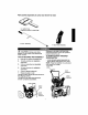
Parts packed separately in carton (not shown full size) 2 - Ignition Keys (Attached to engine in plastic bag) 1 - Crank Assembly 1 - Snow Chute Assembly ,4k CAUTION: Always wear safety glasses or eye shields while assembling snow thrower.
• Remove and discard the packing material from around the snowthrower. • Cut all four corners of the carton from top to bottom and lay the panels flat. • Cut ties securing the clutch control cable to the lower handle and lay cable back away from the motor frame. • Standing at rear, tilt snowthrower forward and remove packaging under motor frame. NOTE: Be careful not to pull auger drive cable from motor frame. • Roll the snowthrower off the carton by pulling on the lower handle.
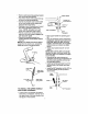
• Carefully remove cotter pin, clevis pin and drilled pin from yoke end of crank rod assembly (see figure below). Flatwasher Snow Chute • Place universal joint into end of worm gear lining up large holes. Insert drilled pin (ensure opening in pin is in line with small openings in universal joint) (see figure below). • Place yoke end of crank rod around universal joint, lining up openings. Insert clevis pin through assembly and secure with cotter pin.
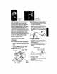
Eo to] KNOW YOUR SNOW THROWER READ THIS OWNER'S MANUAL AND SAFETY RULES BEFORE OPERATING YOUR SNOW THROWER. Compare the illustrations with your SNOW THROWER to familiarize yourself with the location of various controls and adjustments. Save this manual for future reference. r Drive Lever Primer Button Electric Starter Button Discharge Ignition Key Recoil Starter Handle Control Control Auger Drive Lever- Starts and stops the auger and impeller (snow gathering and throwing).
Ignition Key insert to run Auger Drive Clutch pull out to stop TO CONTROL SNOW DISCHARGE Z_ CAUTION: Read owner's manual before operating machine. Never direct discharge toward bystanders. Release the auger control bar and stop the engine before unclogging discharge chute or auger housing and before leaving the machine. The operation of any snow thrower can result in foreign objects being thrown into the eyes, which can result in severe eye damage.
BEFORE STARTING THE ENGINE • If the snow thrower must be moved without the aid of the engine, it is easier to pull the snow thrower by the handles rather than pushing. • Before you service or start the engine, familiarize yourself with the snow thrower. Be sure you understand the function and location of all controls. NOTE: Check tension of clutch cables before starting the engine (see To Adjust The Control Cables paragraph on page 14). • Be sure that all fasteners are tight.
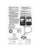
Electric Starter COLDSTART(Seefigureonthispage) • Be sure the auger ddve lever is in the disengaged (Released) position, • Move the throttle control to '_ (Fast) position. • Remove the keys from the plastic bag. Insert one key into the ignition slot. Be sure it snaps into place. DO NOT TURN KEY. Keep the second key in a safe place. • Rotate the choke control to H choke ON position. • Connect the power cord to the switch box on the engine.
• Push the primer button, see figure on page 8, while covering the vent hole as follows: (remove finger from primer button between primes). One time if temperature is above 50oF. Two times if temperature is 50_F to 15°t:. Four times if temperature is below 15°F. • Pull the recoil starter handle rapidly. Do not allow the handle to snap back, but altow it to rewind slowly while keeping a firm hold on the starter handle. • As engine starts warms up move choke lever to "1/2 choke" position.
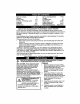
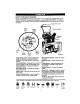
CUSTOMER RESPONSIBILITIES SERVICE DATES SCHEDULE SERVICE RECORDS Fill in dates as you complete regular service After first 2 Hours Before Each Use AS Needed! Every 5 Hours _" Check Engine Oil Level Ever_ 10 Houri Every 25 Hours Each Seaso¢ Before Storage v" Change Engine Oil p- Tighten All Screws & Nuts v" Lubricate Pivot Points Check Auger Clutch Cable Adjustment (See Cable Adj) Check Ddve Bert v* Check Fuel Drain Fuel Replace Spark Plug PRODUCT SPECIFICATIONS HORSE POWER: 5HP DISPLAC
OIL RECOMMENDATION Oil Fill Cap/Dipstick Only use high quality detergent oil rated with API service classification SG. Select the oil's viscosity grade according to your expected operating temperature. NOTE: For extreme cold operating conditions of 0 ° and below, use a partial synthetic OW30 motor oil for easier starting. NOTE: Although multi-viscosity oils improve starting in cold weather, these multiviscosity oils will result in increased oil consumption when used above 32°1.
• Hold the square end of the threaded portion with pliers and adjust the Iocknut in or out until the excess slack is removed (see last figure on page 14). • Pull the cable back through the spring and connect the cable (see last figure on page 14). NOTE: Whenever the auger belt is replaced, the cables will need to be adjusted. • Disconnect the spark plug wire. • Remove the belt cover (see figure below). Cover _ _ TO ADJUST AUGER DRIVE BELT Belt stretches during normal use.
mounting bolt. • Reinstall thebeltcover. vice Center. Engine performance should not be affected at altitudes up to 7,000 feet. For operation at higher elevations, contact your Authorized Craftsman Service Center. • Reconnect the spark plug wire. A(_dve IMPORTANT: Never tamper with the engine governor, which is factory set for proper engine speed. Over speeding the engine above the factory high speed setting can be dangerous.
Z_ CAUTION' Never store your snow thrower indoors'or in an enclosed, poorly ventilated area if gasoline remains in the tank. fumes may reach an open flame, spark or pilot light from a furnace, water heater, clothes dryer, cigarette, etc. To prevent engine damage (if snow thrower is not used for more than 30 days) follow the steps below. SNOW THROWER STORAGE • Thoroughly clean the snow thrower. • Lubricate all lubrication points (see the Maintenance section on pages 12-14).
TROUBLE CAUSE CORRECTION )ifficult starting Defective spark plug Water or dirt in fuel system Replace spark plug Use carburetor bowl drain to flush and refill with fresh fuel. Engine runs erratically Blocked fuel line or low on fuel tank or stale gasoline Clean fuel line; check fuel supply; add fresh fuel (gasoline/oil mix tura if 2-cycle engine). Engine stalls Unit running on CHOKE Move choke lever to OFF position.