CRAFTSMAN 5 Horsepower 24 Inch Dual Stage 120V- Electric Start SNOW THROWER MODEL NO. 536.886440 Caution; Read and follow all Safety Rules and Operating Instructions before first use of this product. SEARS, ROEBUCK AND CO., Hoffman Estates, IL 60179 U.S.A.
TABLE OF CONTENTS WARRANTY STATEMENT.............. SAFETY RULES............................... INTERNATIONAL SYMBOLS . . . . ASSEMBLY ..................................... OPERATION .................................... MAINTENANCE ............................... SERVICE AND ADJUSTMENT .. 2 2 4 6 11 17 20 STORAGE ....................................... 28 TROUBLE SHOOTING CHART .. 29 REPAIR PARTS ...................... . 30 ENGINE REPAIR PARTS ............... 46 SPANISH (ESPAÑOL).....................
9. TRAINING 1. Read the operating and service instruction manual carefully. Be thoroughly familiar with the controls and the proper use of the equipment. Know how to stop the unit and disengage the controls quickly. 2. Never allow children to operate the equip ment. Never allow adults to operate the equipment without proper instruction. 3. Keep the area of operation clear of all per sons, particularly small children and pets. 4.
13. Never operate the snow thrower near en closures, automobiles, window weiis, drop-offs, and the like without proper ad justment of the snow discharge angle. Keep chiidren and pets away. MAINTENANCE AND STORAGE 14. Do not overload the machine capacity by attempting to clear snow at too fast a rate. 2. 15. Never operate the machine at high trans port speeds on slippery surfaces. Look be hind and use care when backing up. 16. Never direct discharge at aiiow anyone in front of the unit. or 3.
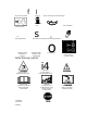
Drive Clutch Forward f I Push To Engage Electric Starter Reverse Auger Clutch Auger Collector Engage i s Fuel Oil Fuel Oil Mixture é B Discharge DOWN Weight Transfer Lift Handle To Engage ■Ô Discharge UP Discharge LEFT Discharge RIGHT Weight Transfer Depress Pedal To Disengage o Transmission Ignition Key Insert To Run, Pull Out To Stop. Safety Warning Symbols i4 Thrown Objects. Keep Bystanders Away. IMPORTANT Read Owner’s Manual Before Operating This Machine.
ASSEMBLY Contents of Parts Bag (actual size) 1 - Owner’s Manual (not shown) 1 - Packet of Fuel Stabilizer (not shown) 1 - Warranty Card (not shown) 2 - Parts bags (not shown) *Non-Assembly Parts, found in toolbox located on belt cover 1- Screw, 5/16-18 X 2 in 1-Split Lockwasher o 1-Flatwasher 11/32ln.
ASSEMBLY Parts packed separately in carton (not shown full size) 2- Ignition Keys (Attached to engine in plastic bag) /V WARNING: Always wear safety glasses or eye shields while assembling snow thrower.
ASSEMBLY 2. Remove and discard the packing material from around the snow thrower. NOTE: If the cables have become dis connected form the clutch levers, rein stall the cables as shown in Figure 4. 3. Cut down all four corners of the car ton and lay the panels flat. 4. Roll snow thrower oft the carton by pulling on the lower handle. CAU TION: DO NOT back over cables. 5. Remove the packing materia! from handle assembly. 6.
ASSEMBLY 7. Install the 3/8” flatwasher and the 3/8” nylon locknut loosely on the eye bolt. 8. Carefully remove cotter pin, clevis pin and universal joint pin from yoke end of crank rod assembly. See Figure 6. 9. Place universal Joint into end of worm gear lining up large holes. In sert universal joint pin (ensure opening in pin is in line with small openings in universal joint). 10. Place yoke end of crank rod around universal joint, lining up openings.
ASSEMBLY 6. Turn crank assembly clockwise and make sure all carriage bolts are tight. SNOW CHUTE ASSEMBLY 1. Turn crank assembly counterclock 2. 3. 4. 5. wise until it stop. Position snow chute on inside of snow chute flange and align the three holes in the snow chute with holes on snow chute flange. (See Figure 9) Place three 5/16-18 carriage bolts from inside of chute as shown in Figure 9. (hardware is found in parts bag). Place three 5/16-18 flatwashers and three 5/16-18 nuts on outside of flange.
OPERATION KNOW YOUR SNOW THROWER READ THIS OWNER’S MANUAL AND SAFETY RULES BEFORE OPERATING YOUR SNOW THROWER. Compare the illustrations with your SNOW THROWER to familiarize yourself with the location of various controls and adjustments. Save this manual for future reference.
OPERATION The operation of any snow thrower can result in foreign objects being thrown into the eyes, which can result in se vere eye damage. Always wear safety glasses or eye shields while operating the snow thrower. We recommend standard safety glasses or a wide vision safety mask for over your glasses. WARNING: Read Owner’s Manual before operating machine. Never direct dis charge toward bystanders stop the engine before unclogging discharge chute or auger housing and before leaving the machine.
OPERATION OH Fill Cap/Dipstick Klick Pin Unlocked Position Single Wheel Drive NOTE: Oil level must be between full and Add mark Figure 13 Figure 14 NOTE: Make sure that the klick pin is in the single wheel drive position of the axle only and not through the locked position. BEFORE STARTING THE ENGINE 1. Before you service or start the en gine, familiarize yourself with the snow thrower. Be sure you under stand the function and location of all controls. 2.
OPERATION Never use engine or carburetor cleaner products in the fuel tank or permanent damage may occur. 1. Fill the fuel tank only with a fresh, clean, unleaded regular, unleaded premium, or reformulated automo tive gasoline. DO NOT use leaded gasoline. Make sure that the con tainer you pour the gasoline from is clean and free from rust or other for eign particles. Never use gasoline that may be stale from long periods of storage in the container.
OPERATION 7. Push the primer button while cov ering the vent hole as follows: Re move finger from primer button between primes. COLD START 1. Be sure auger drive and traction drive levers are in the disengaged (RELEASED) position. 2. Move throttle control to”FAST’ posi tion. 3. Remove the keys form the plastic bag. Insert one key into ignition slot. Make sure it snaps into place. Do not turn key. Keep the second key in a safe place. 4. Rotate choke knob clockwise to the choke ON position. 5.
OPERATION 2. Release the starter handle and let it snap back against the starter. If the engine still fails to start, repeat the two previous steps until the engine starts. Then continue with the direc tions for cold start. To help prevent possible freeze-up of recoil starter and engine controls, pro ceed as follows after each snow remov al job. 1. With the engine running, pull the starter rope hard with a continuous full arm stroke three or four times.
MAINTENANCE CUSTOMER RESPONSIBILITIES SERVICE RECORDS Fill in dates as you complete regular service.
MAINTENANCE PRODUCT SPECIFICATIONS HORSEPOWER 11.0 HP DISPLACEMENT 21.82 cu. in. GASOLINE CAPACITY 4 quarts (unleaded) OIL CAPACITY (20 oz capacity) 5W30 SPARK PLUG; Champion RJ19LM (Gap .030 in.) or equivalent VALVE CLEARANCE: Intake: .010 In, Exhaust: .010 In. prevent rubber friction wheel con tacting the drive disc plate. 6. To grease zerk, use a hand grease gun, lubricate with a Hi Temp EP Moly grease.
MAINTENANCE drive plate or friction wheel come in contact with grease or oil, damage to the friction wheel will result. Should grease or oil come in contact with the disc drive plate or friction wheel, be sure to clean the plate and wheel thoroughly. NOTE: For storage, the hex shaft and sprockets should be wiped with 5W30 motor oil to prevent rusting. 2. Auger Gear Box - The auger gear box is lubricated at the factory and should not require additional lubrica tion.
SERVICE AND ADJUSTMENT WARNING: Always discon nect the spark plug wire and place it where it cannot make contact with spark plug to pre vent accidental starting when mak ing any adjustments or repairs. raise the adjustable skids. Tighten the mounting nuts. See Figure 19. NOTE: For rocky or uneven surfaces, raise the front of the snow thrower by moving the skids down. WARNING: Be certain to maintain proper ground clearance for your particular area to be cleared.
SERVICE AND ADJUSTMENT HOW TO CHECK AND ADJUST THE CABLES The cables are adjusted at the factory and no adjustment should be neces sary. If the cables have become stretched or are sagging adjustment will be necessary. To check for correct adjustment,disconnect the Z-fitting at the drive lever, move the drive lever to the full forward position, just contacting the plastic bumper.
SERVICE AND ADJUSTMENT fraction Drive Belt Auger Drive Be\\ Belt Guide Drive Pulley Idler Pulley TO REPLACE BELTS The drive belts on this snow thrower are of special construction and should be replaced with original equipment belts available from your nearest Craftsman Store. A distributor’s list is supplied in the parts manual. You will need the assistance of a sec ond person while replacing the belts.
SERVICE AND ADJUSTMENT 8. Remove the old auger drive belt. Replace the auger drive belt with an original factory replacement belt available from an authorized service center. 4. Pull the traction drive idler pulley away from the traction drive belt. See Figure 26. Traction Drive Belt Auger Drive ‘Belt 9. Install the new auger drive belt onto the auger drive pulley and onto the drive pulley. Traction Drive Pulley Belt Guide 10. Adjust the auger drive belt.
SERVICE AND ADJUSTMENT HOW TO ADJUST THE BELT GUIDE 1. Disconnect spark plug wire, 2. Remove the screw. Remove the belt cover. See Figure 22. A 2. 3. 3. Engage the auger drive lever. 4. Measure the distance between the belt guide and auger drive belt. The correct distance is 1/8 inch (3.175 mm). See Figure 27. 4. 5. WARNING: Drain the gasoline outdoors, away from fire or flame. Disconnect the spark plug wire. Remove the bolts on each side of the bottom panel. See Figure 28.
SERVICE AND ADJUSTMENT position for the friction v\/heel. See Figure 30. Figure 31 7. Remove the four bolts that hold the bearing plates on each side of the hex shaft. See Figure 32. NOTE: Take special note of the position of the washers and retain ing ring on the hex shaft and the sprocket assembly. 2. Install the bottom panel. See Figure 28. Friction Wheel 3. Tighterr the bolts on each side of the bottom panel. lU 4. Install the bolts on each side of the bottom panel.
SERVICE AND ADJUSTMENT 12. Fasten the bearing plates using the four bolts removed earlier. 13. Make sure the hex shaft turns free ly. 14. Check the adjustment of the friction wheel. See “How To Adjust The Friction Wheel” in this section. 15. Make sure the friction wheel and the disc drive plate are free from grease or oil. TO ADJUST THE CARBURETOR If you think your carburetor needs ad justing, see your nearest Craftsman Store. Engine performance should not be affected at altitudes up to 7,000 feet.
SERVICE AND ADJUSTMENT 2. Be sure spark plug is clean and free of foreign material. Check elec trodes gap with a wire feeler gauge and reset gap to 0.030” if neces sary. See Figure 34. To Replace: 1. 4. Firmly tighten the spark plug in the engine. 5. Feeler Gauge If you need a new spark plug, use only the proper replacement spark plug. 2. Set the gap to 0.030 inches. 3. Before installing the spark plug, lightly coat the spark plug threads with oil or grease to insure easy re moval.
STORAGE WARNING: Never store your snow thrower indoors or in an enclosed, poorly venti lated area. If gasoline remains in the tank, fumes may reach an open flame, spark or pilot light from a fur nace, water heater, clothes dryer, cigarette, etc. NOTE: To prevent engine damage (if snow thrower is not used for more than 30 days) follow the steps below. A 1. To remove gasoline, run the engine until the fuel tank is empty and the engine stops. 2.
TROUBLE SHOOTING TROUBLE CAUSE CORRECTION Difficult starting Defective spark plug. Replace spark plug. Water or dirt in fuel system. Use carburetor bowl drain to flush and refill with fresh fuel. Engine runs erratic Blocked fuel line, empty gas tank, or stale gasoline Clean fuel line; check fuel supply; add fresh gasoline Engine stalls Unit running on CHOKE. Set choke lever to RUN position. Engine runs erratic; Loss of power Water or dirt in fuel system.
CRAFTSMAN 24” 5HP SNOW THROWER 536.886440 FRAME ASSEMBLY 12 SCREW, 5/16-18 710024 13 41 WASHER, SPTLK .31X.58X.08 GUIDE. ROD BELT PLASTIC WASHER 71060 71060 910828 53 WASHER, SPTLK .31X.58X.08 SCREW, 5/16-24X 1.00 SPACER PULLEY, HALF 54 57 WASHER. FLAT .752X.91X.02 BELT, V3L 33.13LG 579861 579932 58 FLATWASHER .765X1.12X.06 SPACER. SLEEVE 712120 59 60 PULLEY, ENGINE 586253 63 67 BELT, V 4L35.6 LG WASHER, FLAT .375X1.25X. 104 581264 50677 68 WASHER.HVSPTLK .38ID SCREW, 3/8-24X1.
CRAFTSMAN 24” 5HP SNOW THROWER 536.886440 ELECTRIC START ASSEMBLY REF. ENGINE 319051 Key No. F-001087J Description Part No.
CRAFTSMAN 24” 5HP SNOW THROWER 536.886440 FRAME ASSEMBLY 344688 Key No. Description Part No. 80 FRAME ASSY 761702-833 88 SCREW. 5/16-18X .50 780055 90 COVER, BOTTOM 583031-853 91 SCREW, 1/4-20X .63 310169 103 IDLER ASSEMBLY 762295 105 PIN, HAIR .38DIAX1.64LG 711682 106 PIN, KL1K3/16” DIA 761761 108 ASSY., SPRING ATTACH 761766 109 BEARING, FL. 53703 110 BOLT, 3/8-16X1.25 CARR. 585781 111 WASHER, FLAT 711617 140 LEVER, IDLER ARM TRACTION 761701 141 BOLT, .625X.
CRAFTSMAN 24” 5HP SNOW THROWER 536.886440 GEAR CASE ASSEMBLY Key No. Description Part No. 300 301 CASE, GEAR, RH CASE. GEAR, LH 10577 303 304 SCREW, 1/4-20X.75 NUT.1/4-20 710025 302635 305 306 NUT, 1/4-20 HEXKEPS SCREW, 3/8-16X.
CRAFTSMAN 24” 5HP SNOW THROWER 536.
CRAFTSMAN 24” 5HP SNOW THROWER 536.886440 DRIVE COMPONENTS y No. Part No. 190 LEVER, ASSY TRACTION CLUTCH 761820 191 BEARING, FLANGE 53703 192 RING, RET E 20864 193 SPRING, RETURN 53818 195 LEVER, SPRING 579937 196 SCREW, 1/4-20X .63 11871 198 NUT, 1/4-20 REGHEXCTRLK 73826 210 DISC, ASSY 211 ZERK, GREASE 583206 215 SHAFT, HEX TRACTION 583155 216 BEARING, TRUNION 85501 583163-853 217 FLATWASHER, .53 X1.00X.O63 71074 221 RING, RETEX 73811 222 FLATWASHER, .680X1.12X.
CRAFTSMAN 24” 5HP SNOW THROWER 536.
CRAFTSMAN 24” 5HP SNOW THROWER 536.886440 AUGER HOUSING ASSEMBLY Key No. Description 480 PULLEY, 4L 6.12X .67 762146 481 SCREW, 5/16-18X.63 577400 482 KEY, SQUARE 71371 485 SPACER, SLEEVE .676X1.00X.53 334514 490 RETAINER, BALL BRNG 582960 491 BEARING, BALL 43846 493 SCREW, 5/16-18X .75 313676 499 NUT, 5/16-18 HEXWDFLLK 710026 500 HOUSING. ASSY 761743-848 ■502 FASTENER, RATCHET 309235 510 BLADE, SCRAPER 22” 581397-853 511 BOLT, 1/4-20X.
CRAFTSMAN 24” 5HP SNOW THROWER 536.
CRAFTSMAN 24” 5HP SNOW THROWER 536.886440 DISCHARGE CHUTE ASSEMBLY Key No. F-001087J Description Part No. 582 BOLT, 5/16-18 X.75 340720 583 WASHER, PLASTIC 12021 584 NUT, 5/16-18 71038 588 WASHER, PLASTIC 6711 592 WASHER, PLASTIC 12021 593 WASHER, PLASTIC 6711 594 FLATWASHER .349X.69X.066 71071 595 WASHER, SPLITLOCK 71060 596 FLATWASHER .349X.69X.066 71071 597 KNOB, T 2/BLADE W/NUT 57171 598 NUT, 5/16-18 REGHEX 71037 599 CARR. BOLT 5/16-18X1.
CRAFTSMAN 24” 5HP SNOW THROWER 536.
CRAFTSMAN 24” 5HP SNOW THROWER 536.886440 HANDLE ASSEMBLY Key No. F-001087J Description Part No. 720 HANDLE, UPPER 9552-853 724 SCREW, 5/16-18X2.75 11234 725 WASHER, FLAT .349X.69X.066 71071 726 WASHER, SPTLK .31X.58X.08 71060 727 NUT, 5/16-18 REGHEX 71037 728 STOP, RED PLASTIC 11261 730 SET OF CLUTCH HANDLE LH & RH 334195 731 SET OF CLUTCH HANDLE LH & RH 334195 733 PIN, CLUTCH HANDLE 4140 734 NUT, PUSH ON CAP 3535 739 BUMPER, RECTANGLE 4049 740 CABLE, CLUTCH 28.
CRAFTSMAN 24” 5HP SNOW THROWER 536.886440 WHEEL ASSEMBLY 679 678 REF. LEFT WHEEL 655 676 REF. RIGHT WHEEL 318542 Key No. F-001087J Description Part No. 650 SHAFT, AXLE 580883 652 SPRKT & HUB 583012 653 SCREW, 1/4-20X2.25 73839 654 NUT, 1/4-20 HEX NYLOCK 780029 655 BRNG, FL 581730 656 CHAIN, ROLLER 579867 LINK, CHAIN MASTER 760504 671 FLATWASHER .765X1.12X.06 712120 673 BUSHING, WHEEL 585591 675 TIRE & RIM 318504 676 SCREW, 1/4-20X1.
CRAFTSMAN 24” 5HP SNOW THROWER 536.886440 SHIFT YOKE ASSEMBLY Key No. I87J Description Part No. 790 ROD, SHIFT 581631-853 791 SCREW, 1/4-20X.75 302628 792 NUT, 1/4-20 REGHEXCTRLK 73826 795 NUT. 1/2-13 HEXJAM 318486 796 KNOB, SHIFT 304438 800 LEVER, SPRING SHIFT 760564 801 SCREW, 1/4-20X.75 302628 802 NUT, 1/4-20 REGHEXCTRLK 73826 811 BEARING, FLANGED 579944 812 ROD, ASSY.
CRAFTSMAN 24” 5HP SNOW THROWER 536.886440 CHUTE CONTROL ROD ASSEMBLY 856 Key No. 87J Description Part No 850 CRANK, ASSY CHUTE 585426 854 HANDLE, CHUTE CRANK 307399 855 FLATWASHER .39X.70X.05 309312 856 E RING 578159 860 EYE BOLT 3/8-16X6.00 581618 861 GROMMET. EYE BOLT 148 862 BOOT 308145 863 NUT. 3/8-16 HEX JAM 71045 864 FLATWASHER .406X.81X.066 71072 865 ADAPTER, BOOT TO HANDLE 309344 866 FLATWASHER .406X.81X.066 71072 867 NUT, 3/8-16 HEXNYL 71046 870 BRACKET.
CRAFTSMAN 24” 5HP SNOW THROWER 536.886440 DECALS Key No.
CRAFTSMAN 4-CYCLE ENGINE MODEL NUMBER 143.
CRAFTSMAN 4-CYCLE ENGINE MODEL NUMBER 143.015005 KEY N0. PART NO. KEY N0. DESCRIPTION PART NO. DESCRIPTION 0 RPM High 3550 to 3850 49 32654 Oil Dipper 0 RPM Low 1850 to 2150 50 33158 Camshaft (BCR) 1 36469A Cylinder (Inc!. 2, 20, 72 & 125) 60 29745 Blower Housing Extension 64 30063 Screw 2 26727 Dowel Pin 64A 8345 Washer 4 0 Oil Drain Extension (Purchase Local) 65 650128 Screw. 10-24 X 1/2” 69 27677A Cylinder Cover Gasket 70 34674C Cylinder Cover (Incl.
CRAFTSMAN 4-CYCLE ENGINE MODEL NUMBER 143.015005 150 31672 Valve Spring 151 31673 Valve Spring Cap 169 27234A Valve Cover Gasket 170 27666 Breather Body 171 31410 Breather Element 172 34146 Valve Cover 173 35350 Breather Tube 174 650783 Screw, 10-24x3/4” 178 29752 Nut & Lock Washer 181 650870 Screw, 1/4-28 x 1-11/16" 182 6201 Screw.
CRAFTSMAN 4-CYCLE ENGINE MODEL NUMBER 143.015005 14 11 \ 12 — F-001087J KEY NO. PART NO. 0 590742 Rewind Starter 3 590740 Retainer 6 590616 Starter Dog 7 590617 Dog Spring 8 590645A 11 590647 Starter Housing Ass’y 12 590535 Starter Rope (Length 98” x 9/64” dia.
CRAFTSMAN 4-CYCLE ENGINE MODEL NUMBER 143.
CRAFTSMAN 4-CYCLE ENGINE MODEL NUMBER 143.015005 F-001087J KEY N0. PART NO. 0 33290E Electric Starter {110 Volt) 2 31749 Retainer Ring 3 33522 Spring Retainer 4 33769 Anti-drift Spring 5A 37332 Nut & Gear (Incl. 2) 6 35461 Drive End Cap Ass’y- (Incl. 7) 7 35450 ”0” Ring 8 35912 Armature 9 0 Housing Ass’y. (Must Purchase Complete Motor) 10A 35452A Brush & Spring Card Ass’y. 13 590500 Thrust Washer 14 33441 Ground Screw 15 35453 Commutator End Cap Ass’y. (Incl.
CRAFTSMAN 4-CYCLE ENGINE MODEL NUMBER 143.
CRAFTSMAN 4-CYCLE ENGINE MODEL NUMBER 143.015005 KEY N0. F-001087J PART NO. DESCRIPTION 0 640084A Carburetor (Incl.
For the repair or replacement parts you need delivered directly to your home Call 7am-7pm, 7days a week 1-800-366-PART (1-800-366-7278) Para ordenar piezas con entrega a domicìlio -1-800-659-7084 For in-house major brand repair service Call 24 hours a day, 7days a week 1-800-4-REPAIR (1-800-473-7247) Para pedir servicio de reparación a domicilio- 1-800-676-5811 For the location of a Sears Parts and Repair Center in your area Call 24 hours a day, 7days a week 1-800-488-1222 For information on purchasing