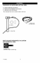
I CRRFTSMRN1 Operator's Manual Snow Thrower 9 Horsepower Electric Start Dual Stage Model 536.887991 CAUTION: Before using this product, read this manual and follow all of its Safety Rules and Operating Instructions. Manual del usario Quitanieves 9 caballos Biet&pico Arranque Modelo de fuerza (hp) el_ctrico 536.887991 PRECAUCI6N: Antes de usar este producto, lea este manual y siga todas las reglas de seguddad e instrucciones de operaci6n. Sears, Roebuck F-O21084L and Co., Hoffman Estates, www.sears.
i (:I :] il :i[o]d[(o] _I i _ _I I_:] WARRANTY STATEMENT ...... SAFETY RULES ............... INTERNATIONAL SYMBOLS .... ASSEMBLY ................... OPERATION .................. MAINTENANCE ............... SERVICE AND ADJUSTMENT... LIMITED TWO-YEAR 2 2 4 6 10 16 19 WARRANTY STORAGE .................... 29 TROUBLESHOOTING TABLE . .. 30 REPAIR PARTS ................ 34 ENGINE REPAIR PARTS ........ 51 SPANISH (ESPAI_IOL) .......... 59 PARTS ORDERING/SERVICE ..
TRAINING 1. Read this operating and service instruction manual carefully. Be thoroughly familiar with the controls and the proper use of the snow thrower. Know how to stop the snow thrower and disengage the controls quickly. 2. Never allow children to operate the snow thrower. Never allow adults to operate the snow thrower without proper instruction. 3. Keep the area of operation dear of all persons, particularly small children and pets. 4.
13.Never operate thesnow thrower near en- MAINTENANCE AND STORAGE closures, automobiles, window wells, drop- 1. Check shear bolts and other bolts at freoffs,and thelikewithout proper adjustment quent intervals for proper tightness to be ofthesnow discharge angle. Keep children sure the snow thrower is in safe working andpetsaway. condition. 14.Donotoverload thesnow thrower capacity2.
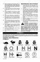
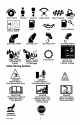
DriveClutch Forward ReverseAuger Clutch Auger Collector Engage Push ToEngage Electric Starter Fuel Discharge DOWN Discharge UP Oil Discharge LEFT Weight Transfer Weight Transfer Transmission LiftHandle To Depress Pedal Engage ToDisengage FuelOilMixture Discharge RIGHT Ignition Key Insert ToRun, PullOutToStop. Safety Warning Symbols DANGER Thrown Objects. Keep Bystanders Away. DANGER Thrown Objects. Keep Bystanders Away. IMPORTANT Read Owner's Manual Before Operating This Machine.
CONTENTS OF PARTS BAG (ACTUAL SIZE) 1 - Owner's Manual (not shown) 1 - Packet of Fuel Stabilizer (not shown) 1 - Warranty Card (not shown) *Non-Assembly Parts,foundintoolboxlocatedon beltcover PARTS PACKED SEPARATELY IN CARTON (NOT SHOWN FULL SIZE) 2- ignition Keys (Attached to engine in plastic bag) F_)2t084L 6
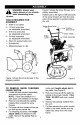
EF,F,F,F,F,F_.-.][.-] _ _vA I-_]ii_4 safety glasses or eye shields ARNING: Always wear while assembling snow thrower. _ TOOLS REQUIRED FOR ASSEMBLY 1 - Knife to cut carton Figure 2 shows the snow thrower completely assembled. References to the right or left hand side of the snow thrower are from the viewpoint of the operator's position behind the unit.
6. TO ASSEMBLE THE HANDLE AND CRANK ASSEMBLY 1. Cut tie holding shift rod to lower handle and move shifter to the first forward gear. 2. Cut and discard the plastic tie that secures the crank assembly. 3. Loosen, but do not remove, the screws, flatwashers. Iockwashers, and hex nuts in the upper holes of the lower handle. See Figure 3. 4. Remove the fasteners and the eyebolt from the lower holes of the lower handle See Figure 5. Install the fasteners that were removed in step 4.
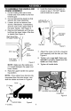
NOTE: If the cables have become disconnected, connect cables as shown in Figure 7. Traction Drive Cable Auger Drive Cable Figure 7 HOW TO SET THE SKID HEIGHT Your snow thrower is equipped with height adjust skids on the outside of the auger housing. To adjust the skid height for different conditions, see To Adjust Skid Height paragraph in the Service And Adjustment section. HOW TO SET THE LENGTH OF THE CABLES The cables were adjusted at the factory and no adjustments should be necessary.
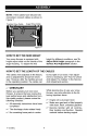
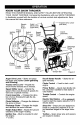
KNOW YOUR SNOW THROWER READ THiS OWNER'S MANUAL AND SAFETY RULES BEFORE OPERATING YOUR SNOW THROWER. Compare the illustrations with your SNOW THROWER to familiarize yourself with the location of various controls and adjustments. Save this manual for future reference.
Theoperation ofanysnowthrower can resultinforeignobjects beingthrown intotheeyes,whichcanresultinsevereeyedamage.Always wearsafety glasses oreyeshields whileoperating thesnowthrower. Werecommend standard safety glasses orawidevisionsafetymaskfor overyourglasses. Speed 3 - Light Speed 4 - Very Light Speed 5,6 - Transport only Engage the traction drive lever (left hand). As the snow thrower starts to move, maintain a firm hold on the handles, and guide the snow thrower along the clearing path.
2. For ease of maneuverability in light snow conditions, disconnect the klick pin from the wheel locked position and push into the single wheel drive position (unlocked axle hole only). See Figure 11. 2. 3. Remove the oil fill cap/dipstick. Check the oil. If necessary, add oil until the oil reaches the FULL mark on the oil fill cap/dipstick (see Figure 12). Do not add too much oil.
Fillthefueltankonlywithafresh, clean,unleaded regular, unleaded premium,orreformulated automotive gasoline.DONOTuseleaded gasoline. Makesurethatthecontainer youpour thegasoline fromiscleanandfreefrom rustorotherforeignparticles. Never usegasoline thatmaybestalefrom longperiods ofstorage inthecontainer. _lb mable.
6, Pushtheprimerbutton as specified below. Remove finger from primer button between pushes. Do not push if temperature above 50 ° F (10 ° C), Push two times if temperature is 50 ° F (10 ° C) to 15°F (-10 ° C). Push four times if temperature is below 15° F (-10 ° C). Push five times if temperature is below 0° F (-18 ° C). 7. (Electric Start) Push down on the starter button until the engine starts. Do not crank for more than 10 seconds at a time. This electric starter is thermally protected.
HOW TO REMOVE OBJECTS FROM AUGER Release auger drive lever. Move throttle lever to stop position. Remove (do not turn) ignition key. Disconnect spark plug wire. Do not place your hands in the auger or discharge chute. Use a pry bar. to ARNING: remove any that may Do item not attempt become lodged in auger without taking the following precau* tions: _1 SNOW THROWING TIPS 1. For maximum snow thrower efficiency in removing snow, adjust ground speed, NEVER the throttle.
SERVICERECORDS Fillin datesasyou complete regular service. Before Each Use Often Every Every Every 5 10 25 Each Before SERVICE Hours Hours Hours Season Storage DATES Chain Lubrication _/ Change Engine Oil _/ Remove Fuel _/ _/ * Adjust after 2 to 4 hours of use. GENERAL RECOMMENDATIONS AFTER EACH USE Run the machine to clear the auger of snow. The warranty on this snow thrower does not cover items that have been subjected to operator abuse or negligence.
PRODUCT SPECIFICATIONS HORSEPOWER 9 HP DISPLACEMENT 19.34cu.in, GASOLINE CAPACITY 4 quarts (unleaded) OIL CAPACITY (20 oz capacity) 5W30 SPARK PLUG: Champion RJ19LIV (Gap .030 in.) or equivalent VALVE CLEARANCE: Intake: .010 In, Exhaust: .010 In. SNOW Hexshaff Figure 13 AUGER GEAR BOX The auger gear box is lubricated at the factory and should not require additional lubrication. If for some reason the lubricant should leak out, have auger gear case checked by a competent repairman.
NOTE: The oil will drain more freely when the engine is warm. 3. After draining all the oil, reinstall the oil drain plug securely. 4. Fill the engine crankcase with S.A.E. 5W30 motor oil, pouring slowly. DO NOT OVERFILL. See "To Add Oil" in the Operation Section. SPARK PLUG 3. Check the spark plug every twentyfive (25) hours. Replace the spark plug if the electrodes are pitted or burned or if the porcelain is cracked.
_.'_o_ V:__ I my:_m_ll_,_l i _vA I_ _i i raise the adjustable skids. Tighten the mounting nuts. See Figure 16. NOTE: For rocky or uneven surfaces, raise the front of the snow thrower by moving the skids down. nect the spark plug disconwire and ARNING: Always place it where it cannot make contact with spark plug to prevent accidental starting when making any adjustments or repairs. _l=lb maintain groundto WARNING:proper Be certain clearance for your particular area to be cleared.
_.'_o_ V:__ I my:_m_ll_,_l i _vA I_ _i i BELT ADJUSTMENT 5. Traction Drive Belt The traction drive belt has constant spring pressure and does not require an adjustment. If the traction drive belt is slipping, replace the belt. See "How To Replace The Belts" in the Service And Adjustment section. Have someone engage auger drive clutch. Check tension on belt (opposite idler pulley). Belt should deflect about 1/2 inch (12.5 mm) with moderate pressure (Figure 18).
_.'_o_ 3, Remove the bottom V:__ I my:_m_ll_,_l i _vA I_ _i i from the engine pulley. Replace the auger drive belt with an original equipment replacement belt available from a Sears service center, panel. Bolt Bottom Panel 8, Install the new auger drive belt onto the auger drive pulley and onto pulley. 9, Adjust the auger drive belt, See "How To Adjust The Auger Drive Belt" in the Service And Adjustment section, Auger Housing 10, Adjust the belt guide.
How To Remove The Traction Drive Belt plate is properly secured (see Figure 21). If the snow thrower will not move forward, check the traction drive belt for wear or damage. If the traction drive belt is worn or damaged, replace the belt as follows. 1. Disconnect the spark plug wire. IIII 2. Remove the auger drive belt. See "How To Remove The Auger Drive Belt" in the Service And Adjustment section. 3. Remove the e-ring from one end of the swing plate axle rod.
_.'_o_ BELT GUIDE !:I _ I mI:1 m_[l_,_l i _vA I_ _i i ADJUSTMENT "Z" Fitting 1. Remove spark plug wire. 2. Have someone engage auger drive. 3. Measure the distance between the belt guide and belt. The distance should be 1/8 inch (3.175 mm) for guide. See Figure 22. Figure 23 __ Auger Idler_ i_a_ Pulley _ t'' d Oa/ - Belt Guide 2. The center of the "Z" fitting should be between the center and top of the hole in the clutch lever.
_.'_o_ B_ I my:1m_[l_,_l i_vA I_ _i i TRACTION DRIVE CABLE ADJUSTMENT 1, Run the engine until the fuel tank is 7, Push the bottom of the traction empty and the engine stops. Stand the snow thrower up on the front end of the auger housing, 3, Loosen the bolts on each side of the bottom panel (see Figure 25). drive cable through the cable adjustment bracket until the "Z" hook can be removed. 8, Remove the "Z" hook from the cable adjustment bracket. Move the "Z" hook down to the next adjustment hole.
_.'_o_ V:__ I my:_m_ll_,_l i _vA I_ _i i HOW TO ADJUST OR REPLACE THE FRICTION WHEEL 5. Install the bottom panel (see Figure 28). 6. Tighten the bolts on each side of the bottom panel. How To Check The Friction Wheel Bolt If the snow thrower will not move forward, check the traction drive belt, the traction drive cable or the friction wheel. If the friction wheel is worn or damaged, it must be replaced. See "How To Replace the Friction Wheel" in this section.
_.'_o_ V:__ I my:_m_ll_,_l i _vA I_ _i i How To Replace The Friction Wheel If the friction wheel is worn or damaged, the snow thrower will not move forward. The friction wheel must be replaced as follows. 1. Run the engine until the fuel tank is empty and the engine stops. Bottom Panel Wheel Figure 31 2. Stand the snow thrower up on the front end of the auger housing (4). (see Figure 28). 3. Disconnect the spark plug wire. 4. Remove the fasteners that secure the right wheel.
_.'_o_ V:__ I my:_m_ll_,_l i _vA I_ _i i 11. Remove the three fasteners that hold the friction wheel to the hub (see Figure 34). 17. Check the adjustment of the friction wheel. See "How To Adjust The Friction Wheel" in this section. 18. Make sure the friction wheel and the 12. Remove the friction wheel from the hub. Slip the friction wheel off the hex shaft. disc drive plate are free from grease or oil. 19. Install the bottom panel (see Figure 31). 13.
_.'_o_ HOW TO REPLACE THE AUGER SHEAR f:1_ I my:1m_[l_,_l i _vA I_ _i i 2. BOLT The augers are secured to the auger shaft with special shear bolts. These shear bolts are designed to break and protect the machine if an object becomes lodged in the auger housing. Do not use a harder bolt as the protection provided by the shear bolt will be lost. Disconnect the spark plug wire. Make sure all moving parts have stopped. 3. Align the hole in the auger with the hole in the auger shaft.
l.'Jll snow thrower indoors in il_ WARNING: Never store oryour an enclosed, poorly ventilated area. If gasoline remains in the tank, fumes may reach an open flame, spark or pilot light from a furnace, water heater, clothes dryer, cigarette, etc. 1, Run the engine until the fuel tank is empty and the engine stops. 2. If you do not remove the gasoline, use fuel stabilizer supplied with unit or purchase Craftsman Fuel Stabilizer No. 3550.
il;Tell:J_]_'_[eZe_ll_[e] TROUBLE CAUSE CORRECTION Difficult starting Defective spark plug. Replace spark plug. Water or dirt in fuel system, Remove fuel from fuel tank. Add fresh fuel. Engine runs erratically Blocked fuel line, empty gas tank, or stale gasoline Clean fuel line; check fuel supply; add fresh gasoline Engine stalls Unit running on CHOKE. Set choke lever to OFF position. Engine runs erratic; Loss of power Water or dirt in fuel system. Remove fuel from fuel tank. Add fresh fuel.
SEARS, ROEBUCK AND CO. Federal and California Emission Control Systems Limited Warranty Small Off-Road Engines CALIFORNIA & US EPA EMISSION CONTROL WARRANTY STATEMENT The U. S. Environmental Protection Agency ("EPA"), the California Air Resources Board ("CARB") and Sears, Roebuck and Co. are pleased to explain the Federal and California Emission Control Systems Warranty on your new small off-roed engine.
ershallpayanycharges formaking service Sears, Roebuck and Co. according to Subseccallsand/or fortransporting theproducts to tion 4 below. Any such part repaired or reandfromtheplace where theinspection and/ placed under the ECS Warranty shall be orwarranty work isperformed. Thepurchaserwarranted for any remainder of the ECS Warshallberesponsible foranydamage orlossin- ranty Period. curred inconnection withthetransportation of warranted, emissions-related part anyengine oranypart(s) thereof submitted for 2.
EMISSION-RELATED PARTS useshallnotreduce Sears. Roebuck andCo. ECSWarranty obligations. INCLUDE THE FOLLOWING: 9.Unapproved add-on ormodified parts may 1. Carburetor Assembly and its Internal Comnotbeused tomodify orrepair aSears, Roe- ponents buck andCo.engine. Such usevoids thisECS a) Fuel filter Warranty andshallbesufficient grounds for Carburetor gaskets disallowing anECSWarranty claim. Sears, b) Roebuck andCo.shall notbeliable hereunderc) Intake pipe forfailures ofanywarranted parts ofaSears, 2.
CRAFTSMAN 9HP SNOW THROWER ENGINE 6 536.887991 20 25-2 22 24 !6 8 18 25-3 23 \ 12 \ 25-2 / 25-5 / olz25- / 14 Re£Ddve Page 3 Ref. Auger Housing Page Key No. Key No. Part No. Description Part No. Description 2 143.
CRAFTSMAN 9HP SNOW THROWER 536.887991 ELECTRIC STARTER 8 9 7 \ ES100A Key No. F_)21084L Part No.
CRAFTSMAN 9HP SNOW THROWER FRAME 536.887991 169 170 160 / 106 162 \ lO5 lO8_ 1 111 Re£ Auger Housing Page 120qo Re£ Drive Page 91 / 9O 168 91 103 149 107 Key No. Part No. Description Key No. Part No.
CRAFTSMAN 9HP SNOW THROWER GEAR CASE 536.887991 306 340 _;!i310 321 327 jz 311 330 304 300 310 303 Key No. Pa_ No, Description Key No. Part No.
CRAFTSMAN 9HP SNOW THROWER DRIVE Ref. Shift Yoke Page 536.887991 Ref. Frame Page _---_ R/#f_{Nheel _ 229 200 \ 225 \ Ref. Whee Page 206 \ 227 / 201 236 / / 204 203 230 \ 218 220 207 215 \ Ref. Wheel Page 210 238 \ 208 212 218 217 213 DR100A F_)21084L 38
CRAFTSMAN F_)21084L 9HP SNOW THROWER DRIVE 536.887991 Key No. Pa_ No. 200 1501092 Description 201 579851 CHAIN, ROLLER #42x19.00 203 334163 BEARING AND RETAINER, ASSY 204 579858 WASHER 206 780055 SCREW, TAP 5/16-18x0.5 207 1501236 ASSY, HEX SHAFT 208 579868 CHAIN, ROLLER #36x18.00 210 337029 BEARING, TRUNION 212 1501435 WHEEL, 213 001X38 SCREW, 1/4-20 x 0.
CRAFTSMAN 9HP SNOW THROWER 536.887991 DISCHARGE CHUTE 596 600 6OO 597 583 584 599 582 600 602 603 _ 610 601 609 609 606 611 6O7 \ CHUTE100B F_)21084L 40
CRAFTSMAN Key No. F_)21084L 9HP SNOW THROWER 536.887991 DISCHARGE CHUTE Part No. Description 582 2x100 SCREW, 5/16-18 583 71071 WASHER, 584 71038 NUT, 5/16-18 596 71071 WASHER 597 1501260 WINGKNOB 599 002X97 BOLT, 5/16-18 600 762222 CHUTE ASSEMBLY 601 2x100 BOLT, 5/16-18Xl.00 602 71071 WASHER, 603 71038 NUT, 5/16-18 606 585214 YZ CHUTE COLLAR 607 02x101 SCREW, 1/4-20 X.75 CARR.
CRAFTSMAN 9HP SNOW THROWER AUGER HOUSING 5OO 50_ 511 521 5OO 514 540 F_)21084L 42 536.
CRAFTSMAN Key No. F_)21084L 9HP SNOW THROWER AUGER HOUSING 536.887991 Part No. Description 480 583146 PULLEY, 4L 8.40 OD. 482 2001022 KEY, SQUARE 3/16 X 3/4 484 15X112 NUT, .
CRAFTSMAN 9HP SNOW THROWER HANDLE 536.887991 731 766 729 730 734 / 734 729 740 / 741 746 757 756 725 758 764 / / \\ Refpa%negine _ ) 759 764 760 HDLI05A F_)21084L 44 762
CRAFTSMAN Key No. F_)21084L 9HP SNOW THROWER HANDLE Pad No. 536.887991 Description 720 1501205E701 721 1501206E701 HANDLE, UPPER RH 724 11234 SCREW,_16-18X2+75 725 71071 WASHER, FLAT 726 71060 WASHER, SPTLK .31X.58X.
CRAFTSMAN 9HP SNOW THROWER CHUTE ROD 536.887991 856 855 862 Ref. Handle Assy / 861 \ 864 870 8!7_ 852-9 / 852-5 852-8 ~ =_ 852-13 Ref. Auger Housing Assy _" 852-10 852-11 _ 852-1 868 )_ - 852-2 _\\\\ \ \ \ \ / 852-7 F_)21084L 46 / 852-3
CRAFTSMAN Key No. F_)21084L 9HP SNOW THROWER CHUTE ROD 536.887991 Part No.
CRAFTSMAN 9HP SNOW THROWER SHIFT YOKE 536.887991 796 790 792 801 791 8OO 814 813 8O2 / 812 SYOKEIOOA Key No. F_)21084L Part No.
CRAFTSMAN 9HP SNOW THROWER PANEL 536.887991 770 _ 771 f 772 771_ 772 PANEL101A Key No. Part No. Description 770 1501203E549 PANEL 771 002x99 BOLT, CARRIAGE 772 71067 WASHER 773 15X145 NUT 1/4-20 NYLOCK YZ DECALS Part No.
CRAFTSMAN 9HP SNOW THROWER WHEELS 536.887991 679 678 / 680 671 654 650 JR 655 652 676 Re£ Drive Page 655 / 671 673 WHL100A 677 Part No. Description 65O 1501284 YZ SHAFT, AXLE 652 1501089 SPRKT & HUB 653 0tx193 SCREW, 1/4-20X2,25 654 15X145 NUT+ 1/4-20 HEX NYLOCK YZ 655 1501114 BEARING, AXLE 671 712120 WASHER, FLAT 673 1501138 BUSHING, WHEEL 675 1501022 TIRE & RIM -RIGHT 676 577015 SCREW, 1/4-20Xl.
CRAFTSMAN 4-CYCLE ENGINE MODEL NUMBER 143.039005 ,y1 70 10 69 48 _ d_t',.
CRAFTSMAN KEY NO. PART NO. 4-CYCLE ENGINE MODEL NUMBER PART NO. 143.039005 DESCRIPTION KEY NO. RPM High 3550 to 3850 65 650128 Screw, 10-24x RPM Low 2000 69 37342 Cylinder Cover Gasket DESCRIPTION 1/2" 1 2 35385 27652 Cylinder (Incl. 2, 20 & 72) Dowel Pin 70 35376A Cylinder Cover (Incl.
CRAFTSMAN 4-CYCLE ENGINE MODEL NUMBER 143.039005 149A 35862 Valve Spring Cap 292 26460 Fuel Line Clamp 150 27881 Valve Spring 298 650665 Screw, 1/4-15 x 3/4" 151 32581 Valve Spnng Keeper 300 34186A 169 27896A Valve Cover Gasket Fuel Tank (incl.
CRAFTSMAN F_)21084L 4-CYCLE ENGINE MODEL NUMBER 143.
CRAFTSMAN 4-CYCLE KEY NO. F_)21084L ENGINE MODEL NUMBER 143.039005 PART NO.
CRAFTSMAN 4-CYCLE ENGINE MODEL NUMBER 29 \ 23 14---,_,"-16 26 \ 10 \7 6 5A F_)21084L 143.
CRAFTSMAN 4-CYCLE KEY NO. F_)21084L ENGINE MODEL NUMBER PART NO. DESCRIPTION 0 33329E Electric Starter (110 Volt) 1 33451 Dust Cover 2 33842 Retainer Ring 3 33430 Spring Retainer 4 33431 Anti-drift 5A 37050 Gear & Nut (IncL 2) 8 35449 Drive End Cap Ass'y. (Incl. 7) 7 35450 "O" Ring 8 35915 Armature 9 35451B Housing Ass'y. 10 35452A Brush Card Ass'y.
CRAFTSMAN 4-CYCLE 12 KEY NO. F_)21084L ENGINE MODEL NUMBER 143.039005 13 PART NO. DESCRIPTION 0 590749 Rewind Starter 1 590599A Spring Pin (IncL 4) 2 590600 Washer 3 590679 Retainer 4 590601 Washer 5 590676 Brake Spring 6 590680 Starter Dog 7 590412 Dog Spring 8 590682 Pulley & Rewind Spring Assembly 11 590750A Starter Housing Assembly 12 590535 Starter Rope (Length 98" x 9/64" dia.
[ilo] 11d1111"[o] PLEAS DE REPUESTO ............ PLEAS DE REPUESTO- MOTOR .... GARANTIA ..................... REGLASDE SEGURIDAD .......... SIMBOLOSINTERNACIONALES..... ENSAMBLAJE................... 34 51 59 59 62 64 OPERACI(_N .................... MANTENIMIENTO ................ SERVIClOY AJUSTES ............. ALMACENAMIENTO............... TABLADE LOC_,UZACI(_NY REPARACIONDE AVERIAS ..... PEDIDODE PIEZAS/SERVICIO....... 68 74 77 87 88 92 [eT.,1 z_.,11 k ill.
CAPACITACI6N 1. Lea con atenci6n las instrucciones en el manual de operaci6n y servicio. Familiaricese completamente con los controles y el uso apropiado del quitanieves. Aprendaa detener el quitanieves y a desenganchar r_pidamente los controles. y/o del sol hace que el combustible se expanda. 5. 2. Nunca permita a niSos operar el quitanieves. Nunca permita que adultos opeten el quitanieves sin la instrucci6n apropiada. 3. Mantenga el Area Iibre de personas, especialmente niSos pequefios y mascotas.
na/propulsor ytodas laspartes m6viles ruedas, juegos dearranque el_ctdco, seencaentren detenidas, yqaetodos los etc.). controles est6n desenganchados. Desco-19.Nanca opere elquitanieves sintener buenecte elcable delabujiaymant6ngalo navisibilidad oiluminaci6n. AsegQrese alejado delabujia para evitar unarransiempre quetiene buena estabilidad, y queaccidental. sajete con firmeza el mango. Camine; nunca corra. 9. Tome todas lasprecauciones posibles al dejarelquitanieves desatendido. Desen-20.
IMPORTANTE: Muchos de estos simbolos est_n colocados en su quitanieves o estan impresos en los manuales que vienen con el producto. Antes de operar el quitanieves aprenda y comprenda el objetivo de cada simbolo.
Simbolos de control y operacibn Combustible f Descarga hacia ABAJO Transferencia de peso Levante el mango pars enganchar, Mezcls de combustible y aceite Aceite d Descarga hacis ARRIBA Descsrga hscia la IZQUIERDA Transferencia de peso Presione el pedal para desengsnchar. Descarga hacia la DERECHA Llave de encendido Insertar para marcha, Retirar para parar. Simbolos de advertencia de seguridad PELIGRO Objstos lanzados. Mantenga alejados a los trsnse_ntes. PELIGRO Objetos lanzados.
CONTENIDO DE LA BOLSA DE PARTES (TAMANO REAL) 1 - Manual det Propietario (no se muestra) 1 - Paquete de estabilizador de combustible (no se muestra) 1 - Tarjeta de garantia (no se muestra) *Las partes que no necesitan ensamblado se encuentran en la caja de herramientas ubicada en la cubierta de la correa.
La Figura 38 muestra el quitanieves completamente ensamblado. La referencia a los lados izquierdo y derecho del quitanieves se hace desde la posici6n del operador cuando 6ste se encuentra detr_s de la unidad. gafas de seguridad o protecto* DVERTENCIA: Siempre use res para los ojos mientras ensambla el quitanieves.
C6MO ENSAMBLAR EL MANGO Y EL CONJUNTO DE LA MANIVELA Conexi6n en "Z" 1, Corte los amarres que sujetan la palanca de cambios al mango inferior y mueva la palanca a la primera velocidad de avance, 2, Corte y deseche el amarre de pl_stico que sujeta el conjunto de la manivela. Cable de control 3, Afloje pero no quite los tornillos, arandelas planas, arandelas de seguridad y tuercas hexagonales que se encuentran en los agujeros superiores del mango inferior.
NOTA: Si los cables se han desconectado, con6ctelos como se muestra en la Figura 43.
CONOZCA SU QUITANIEVES LEA ESTE MANUAL DEL USUARIO Y LAS REGLAS DE SEGURIDAD ANTES DE USAR USAR SU QUITANIEVES, Compare las figuras con su QUITANIEVES para familarizarse con las posiciones de los diversos controles y ajustes, Guarde este manual para referencia futura.
Laoperaci6n decualquier quitanieves puede ocasionar queobjetos extra£Los sean lanzadosconfuerza hacia losojos,Iocaalpodria resultar enlesiones graves. Usesiempre gafas deseguridad o protectores para los ojosmientras opera elquitanieves. Serecomiendan lasgafas deseguridad est_ndar olam_scara deseguridad devisi6n amplia parausada sobre losanteojos. del propietario antes de operar ADVERTENCIA: Lea el manual la mbquina. Nunca dirije la descarga hecia los transet_ntes.
J Pasador klic_._ Posici6n de desenganche .____i t_P"_ .. racclon en una sola Uueda Figura 47 NOTA: El nivel del aceite deber& estar entre la marca FULL (lleno) y la marca NOTA: AsegQrese de que el pasador klick est6 en la posici6n de tracci6n de una sola rueda en el eje solamente, y no est6 insertado a tray,s de ]a posici6n de enganche. ADD (agregar) Figura 48 4. Apriete flrmemente la tapa/varilla cada vez que revise el nivel de aceite.
Llene eltanque solamente congasolina fresca,limpia, regular sinplomo, s_per sinplomoogasolina automotor reformulada. NO usegasolina conplomo. Aseg_rese deque el recipiente que contiene la gasolina a utilizar, est_ limpio y sin 6xido u otras partico]as extrafias. Nunca use gasolina que pueda estar vencida debido a su prolongado almacenamiento. arranque est& equipado con un DVERTENCIA: El motor de cable de alimentacibn y enchufe trifilar, diseSados para funcionar con corriente dom_stice de 120 voltios CA.
tomacorrientes trifilar de120voltios CA, conectado atierra. 6. Empuje elbotbn cebador de la manera indicada a continuaci6n. Quite el dedo del bot6n cebador entre cebados. No use la funci6n de cebado si la temperatura esta sobre 50 ° F (10 ° C). • Oprima el bot6n dos veces si la temperatura est_ entre 50 ° F (10 ° C) y 15 ° F (-10 ° C). • Oprima el bot6n cuatro veces si la temperatara se encuentra por debajo de los 15 ° F (-10 ° C).
C6MO RETIRAR OBJETOS ATASCADOS DE LA BARRENA Mueva la palanca de control de aceleraci6n a la posici6n "parar". Retire (sin girar) la Ilave de ignici6n. car ning_n objeto etascado en _k ADVERTENCIA: No intente sale barrena sin tomar las precauclones siguientes. Desconecte No coloque las manes en la barrena o canal de descarga. Use una barra de apalancamiento para sacar el objeto atascado.
hVir:ll i I _ 1i hVlll_1i tie] REGISTROSDE SERVIClO Anate las fechas a medidaque completeel servicio _ Antes de cada uso A menudo Cada 5 horas Cada 10 horas Cada 25 horas Cada temporada Antes FECHA de DEL guardar SERVICIO ...................................................... Lubricaci6n de la cadena _/ Cambiar el aceite del motor %/ %/ !! Vaciar el tanque de combustible %/ * Ajustar despu6s de 2 a 4 horas de use.
hVff:1_i I _ _i hVAIl_ _i tie] ESPECIFICACIONES CABALLOS FUERZA DE 9 HP ;ILiNDRADA 19.34cuJn CAPACiDAD GASOLINA DE CAPACIDAD ACEITE DE BUJiA: ESPACIODE V,&LVULAS: PRECAUCI(_N: No permita que la grasa entre en contacto con la rueda de friccibn ni con la placa del disco de propulsibn. 6. Instale el panel inferior. 4 cuartos (sin plomo) 20 onzas, 5W30 Champion RJ19LM (Entrehierro 0,030 Eje hexagonal Entrada: 0,010 pig. Escape: 0,010 pig.
hVff:_f_ i I _ _i hVAIl_ _i tie] CAMBIO DE ACEITE NOTA: El aceite fluira mejor si el motor est_ caliente, 3. 1. Coloque el quitanieves de manera tal que el tap6n de drenaje del aceite sea el punto mas bajo del motor. 2, Quite el tap6n de drenaje del aceite y la tapalvarilla indicadora del nivel de aeeite, Drene el aceite en un recipiente apropiado. 4. BUJiA Una vez que haya sacado todo el aceite, coloque nuevamente el tap6n de drenaje en su lugar y apri6telo para que quede seguro.
_I] Ill i_]_I_[*'_III_ 4. Afloje las tuercas de montaje que sujetan los patines de ajuste de altura. Para bajar ]a parte delantera del quitanieves, suba los patines. Apriete las tuercas de montaje. Vea la Figura 52. el arranque accidental del moADVERTENCIA: Para prevenir tor, siempre desconecte el cable de la bujia y mant_ngalo alejado de _sta mientras realiza ajustes o reparaclones a la unidad.
_I] Ill i_]_I_[_'_III_ AJUSTE DE LAS CORREAS beda ceder media pulgada (12,5 ram) con presi6n moderada (Figura 54). Puede que tenga que mover la polea guia m_s de una vez para conseguir la tensi6n correcta. Polea de Correa de propulsibn La correa de propulsi6n tiene una presi6n de resorte constante y no requiere ningt_n ajuste. Si nota que empeza a resbalar, reempl_cela. Consulte "C6mo reemplazar la correa" en la secci6n de Servicio y Ajustes.
_I] Ill i_]_I_[_'_III_ 2, Afloje los pernos a cada lade del panel inferior (Figura 55), 3, Quite el panel inferior. Perno Panel inferior barrena y de la polea del motor, Instale una correa de propulsibn de la barrena nueva original de f_brica que haya comprado en un centro de servicio Sears. 8, Instale la correa de propulsibn de la barrena nueva en la polea de propulsibn y en la polea.
_I] Cbmo desmontar propulsibn Ill la correa de i_]_I_[_'_III_ sujeta (Figura 57). SI el quitanieves no se mueve hacia adelante, asegerese de que la correa de propulsi6n no est6 excesivamente desgastada o daSada. SIIo est,, reempl_cela de la siguiente manera. 1. Desconecte el cable de la bujia. 2. Quite la correa de propulsi6n de la barrena. Consulte "C6mo desmontar la correa de propulsi6n de la barrena" en la secci6n de Servicio y Ajustes. 3.
_I] AJUSTES Ill DE LA CORREA i_]_I_[_'_III_ GUIA Accesono 1. Quite el cable de la bujia. 2. Pida a alguien que ponga el propulsor de la barrena. 3. °Z" Mida la distancia entre la guia de la correa y la correa. La distancia debe ser de 1/8 de pulgada (3,175 mm) para la guia. (Figura 58). / _ Guia de Polea guia "_ J _ _ \ _ _,,_t\"" de a 2. 1/8 pig. (3,175 mm) \\ barrena fennciona" miento acor,oa t _ -_' _ .___. \\ \ de la 1, Deje el motor en marcha hasta que el tanque de combustible que
_I] Ill i_]_I_[_'_III_ AJUSTES DEL CABLE DE PROPULSI6N 1, Deje el motor en marcha hasta que 7, Meta la parte inferior del cable de el tanque de combustible quede vacioy el motor se pare, 2, Levante el quitanieves con el extremo frontal del alojamiento de la barrena hacia abajo. 3, Afloje los pernos a cada lado del panel inferior (Figura 61), Pemo propulsibn por el soporte de ajuste del cable hasta que pueda sacar el gancho "Z". 8. Saque el gancho "Z" del soporte de ajuste del cable.
_I] Ill i_]_I]-'II_ C6MO AJUSTAR O REEMPLAZAR Cbmo revisar LA RUEDA DE FRICCION la rueda de friccibn 12 y 13 pulgs. 4-1/8" 16 pulgs. 4-5!16" Si la rueda de fricci6n no est_ en la posici6n correcta, ajQstela de acuerdo alas instrucciones siguientes. Si el quitanieves no avanza, revise la cerrea de propulsi6n por tracci6n, el cable de propulsi6n o la rueda de fricci6n. Si la rueda de fricci6n est_ gastada o daSada, hay que cambiarla. Ver "Reemplazo de la rueda de fricci6n" en esta secci6n.
_I] Ill i_]_I_[_'_III_ Cbmo reemplazar la rueda de fricciOn Si la rueda de fricciOn est_ gastada o da5ada, el quitanieves no avanza. La rueda de fricciOn se debe cambiar de la siguiente manera. Panel inferior 1. Deje el motor en marcha hasta que el tanque de combustible quede vacioy el motor se pare. 2, Ponga el quitanieves en posiciOn vertical sobre la parte delantera del alojamiento de la barrena (4). (Figura 64). 3. Desconecte el cable de la bujia.
_I] Ill i_]_I_[_'_III_ 12. Quite la rueda de friccibn del cu* bo. Deslice la rueda de friccibn fuera del eje hexagonal. 13. Instale la nueva rueda de fricci6n en el cubo con los sujetadores que quit6 antes. 18. AsegOrese de que la rueda de fricci6n y la placa del propulsor de disco no tienen ni grasa ni aceite. 19. Instale el panel inferior (Figura 67). 20. Apriete los pernos a cada lado del panel inferior. 14. Instale el eje hexagonal y los cojinetes con los cuatro pernos que quit6 antes (Figura 71).
_I] C6MO REEMPLAZAR SEGURIDAD LOS PERNOS Ill i_]_I__,III_ DE 2. Desconecte el cable de la bujia. Aseg_rese de que todas las piezas m6viles se hayan detenido. 3. Alinee el agujero de la barrena con el agujero del eje de la barrena. Instale el nuevo pasador de seguridad y espaciatier. Figura 72. 4. Conecte el cable de la bujia. DE LA BARRENA Las barrenas estan sujetas al eje de la barrena con pemos de seguridad especiales.
1. Deje el motor en marcha hasta que el tanque quede vacio y el motor se pare. 2. Si no quiere sacar la gasolina, use el estabilizador de combustible provisto con la unidad, o compre estabilizador de combustible Craftsman NQm. 3550. Ahada el estabilizador de combustible a cualquier cantidad de gasolina que permanezca en el tanque para minimizar los dep6sitos de goma y _cido.
PROBLEMA CAUSA CORRECCION Dificultad de arranque Bujia defectuosa. Reemplace la bujia defectuosa. Agua o suciedad en el sistema de combustible. Saque el combustible del tanque. ASada combustible fresco. El motor funeiona err_ticamente Linea de combustible bloqueada, falta de combustible o mezcla de combustible vieja, Limpie la linea de combustible; revise la existencia de combustible en el tanque, agregue gasolina fresca si es necesario.
SEARS, ROEBUCK AND CO. Garantia limitada de cumplimiento con el Sistema Federal de control de emisiones y con el sistema de control de emisiones del Estado de California Motores peque_os para vehiculos todo terreno CONTROL DE EMISIONES DE CALIFORNIA Y DE LA AGENClA DE PROTECCI_N AMBIENTAL (EPA) DE E.U.A.
Sears, Roebuck and Co., o a Sears, Roebuck and Co., a11400-473-7247 (llamada gratuita en E.U.A.). NOTA IMPORTANTE Esta declaraci6n de garantia explica los derechos y ]as obligac]ones qoe usted tiene de conform]dad con la Garantfa del Sistema para el Control tie Emisiones ("Garantfa SCE"), la cual Sears, Roebuck and Co., le proporciona de conformidari con ]as ]eyes de California. Consulte tambi6n ]as Garantias Limitarias de Sears, Roebuck anti Co.
Garantia SCE deber& garantizarse porelresto aprobada porSears, Roebuck andCo.para delPeriodo delamisma, utilizarse eneldesempeSo decualquier mantenimiento o cambio delaGarantia SCE, la 3.Cualquier parte garantizada yrelacionadacoalseproporcionar_ sin cargo alguno para el conemisiones queseespecifique para cam- propietario. Dicho usonoreducira lasobligabio,deconformidad conelManual delPropie- clones deSears, Roebuck andCo.conforme tario,deber_ garantizarse potelperiodo de alaGarantia SCE.
Get it fixed, at your home or ours! Your Home For repair in your home of all major brand apphances, lawn and garden equipment, or heating and coohng systems, no matter who made it, no matter who sold it! For the replacement parts, accessones and owner s manuals that you need to do-it-yourself For Sears professional installation of home apphances and _tems like garage door openers and water heaters 1-800-4-MY-HOM Efl Anyhme tl-800-469-4663) day or night (U S A and Canada) www.sears,corn www.