2610913327 Owner's Manual CRRFTSMRN ROTARY POWER TOOLS Model Nos. 572.610830 572.610960 & 572.610950 Caution: • Safety Before using this product, read this manual and follow all its Safety Rules and • ° Operation Maintenance ° Parts Operating Instructions. Sears, Roebuck 2610913327 and Co.
Table of Contents Warranty Page ........................................................ Power Tool Safety Rules 2 .......................................... Symbols ........................................................ Functional Description and Specifications 3-6 7 ............................ 8-9 Assembly .................................................... Operating Instructions ..........................................
Read and understand to follow all instructions listed below, may result all in instructions. electric shock, Failure fire and/or serious personal injury. SAVE THESE Work Area Keep your work area clean and well lit. Cluttered benches and dark areas invite accidents. Do not operate power tools in explosive atmospheres, such as in the presence of flammable liquids, gases, or dust. Power tools create sparks which may ignite the dust or fumes.
Do not use tool if switch does not turn it "ON" or "OFF". Any tool that cannot be controlled with the switch is dangerous and must be repaired. Disconnect the plug from the power source before making any adjustments, changing accessories, or storing the tool. Such preventive safety measures reduce the risk of starting the tool accidentally. Store idle tools out of reach of children and other untrained persons. Tools are dangerous in the hands of untrained users. Maintain tools with care.
Allow brushes to run at operating speed for at least one minute before using wheel. During this time no one is to stand in front or in line with the brush. Loose bristles or wires will be discharged during the run-in time. objects objects Wire and bristle brushes must never be operated at speeds greater than 15,000/min. Direct the discharge of the spinning wire brush away from you.
When using the steel saws, cutoff wheels, high speed cutters or tungsten carbide cutters, always have the work securely clamped. Never attempt to hold the work with one hand while using any of these accessories. The reason is that these wheels will grab if they become slightly canted in the groove, and can kickback causing loss of control resulting in serious injury. Your second hand should be used to steady and guide the hand holding the tool. When a cutoff wheel grabs, the wheel itself usually breaks.
, II "T IMPORTANT: Some of the following symbols and learn their meaning. Proper interpretation tool better and safer. Symbol may be used on your tool. Please study them of these symbols will allow you to operate the Name Designation/Explanation V Volts Voltage (potential) A Amperes Current Hz Hertz Frequency (cycles per second) W Watt Power kg Kilograms Weight min Minutes Time s Seconds Time Diameter Size of drill bits, grinding O ... I :O nO No load speed ...
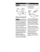
Disconnect the plug from power accessories, source beforeSuch making any assembly, adjustments or the changing preventive safety measures reducethe riskof starting the tool accidentally, RotaryTool 610830 & 610960 HOUSING C_ VENTILATION OPENINGS COLLET NUT _q SHAFT LOCK VENTILATION (610830 SINGLE SPEED) BUTTON OPENINGS (610960 TWO SPEED) RotaryTool 610950 CORD SOFT GRIP HOUSINGCAP COLLET NUT COLLET VENTILATION OPENINGS SHAFTLOCK BUII'ON VENTILATION OPENINGS NOTE: For tool specifications VARI
Flex-Shaft 53033 CuttingGuide53141 GroutRemovalKit 53052 DEPTH GUIDE _ DEPTH ADJUSTMENT INSiRT___ GUIDE _ _ SCREW SCiEW RightAngleAttachment53002 COLLAR _ \ \ COLLET __ _"_ ADJUSTMENT I CO'LET _ ,'_.',.
COLLETIDENTIFICATION CHART-- Colletsizes ca_ _ Always unplug tool before changingrotary accessories, changing collets or servicing your rotary tool. beidentified by the rings on thebackend of collet./ I SHAFTLOCK COLLET BUTTON_ | | | 1/8 "Collet has no rings. J KEYLESS CHUCK WRENCH T COLLET TOLOOSEN COLLET COLLET -- To loosen, first press shaft lock button and rotate the shaft by hand until the lock engages the shaft preventing further rotation. collet a 1/4 turn.
KEYLESS CHUCK -- The keyless chuck holds various accessories with shank sizes 1/32" to !/8" and is intended for light duty accessories such as drill bits, sanding drums, polishing accessories, wire and bristle brushes and cut-off wheels. The keyless chuck allows you to change accessories frequently, quickly and easily.
The Rotary Tool is a handful of high-speed power. It serves as a carver, grinder, polisher, sander, cutter, power brush, drill and more. The Rotary Tool has a small, powerful electric motor, is comfortable in the hand, and is made to accept a large variety of accessories including abrasive wheels, drill bits, wire brushes, polishers, engraving cutters, router bits, and cutting wheels. Accessories come in a variety of shapes and permit you to do a number of different jobs.
USING THE ROTARY POWER TOOL The first step in learning to use the Rotary Tool is to get the "feel" of it. Hold it in your hand and feel its weight and balance. Feel the taper of the housing. This taper permits the Rotary Tool to be grasped much like a pen or pencil. The Variable Speed tool has a unique comfort grip on the nose and back seating, which allows the user added comfort and control during use. You can feel the difference! When you turn on the tool for the first time, hold it away from your face.
OPERATJN G SPEEDS S_ow speeds (15,000 RPM or less) usually are best for polishing operations employing the felt polishing accessories. They may also be best for working on delicate projects as "eggery" work. delicate wood carving and fragile model parts. All brushing applications require lower speeds to avoid wire discharge from the holder. Set the speed indicator to fit the job; to achieve the best job results when working with different materials, the speed of the Rotary Tool shoukt be regulated.
3. Wood should accessory. Look this table over and become familiar with it. 4. Iron or steel should be cut at high speed if using tungsten carbide accessory, but at slower speeds if using high speed steel cutters. If a high speed steel cutter starts to chatter -- this normally means it is running too slow. Ultimately, the best way to determine the correct speed for work on any material is to practice for a few minutes on a piece of scrap, even after referring to the chart.
Flexible Shaft Lubrication The flexible shaft should be lubricated after every 25-30 hours of use. To lubricate, unscrew the flexible shaft assembly from the motor housing. Pull the center core out of the flexible shaft assembly. Wipe a very thin film of a good quality, high temperature grease on to the center core. Not bits. for Use use with with routerrouter bits will cause kickback. 1.
Do not operate thea sharp flexible shaft with bend (A). This can generate excessive heat and will reduce tool and flex-shaft life. The recommended minimum is 6" radius (El). Contents 1 1 of 53033 Flex-shaft Attachment Description Flex-Shaft Assembly (42" long) Driver Cap A. Cutting Guide53141 The cutting guide (sold separately) completely assembled and ready use in a variety of materials up to Match the bit type to the material Always hold the tool firmly, using B. steady pressure to make cuts.
Grout Removal Kit 53052 The grout removal attachment comes completely assembled and ready to use. Use the 1/16" bit that comes with the grout removal kit for tiles spaced more than 1/16" apart. If your tiles are spaced more than 1/8" apart, it is recommended that you use the 53166 (1/8") bit (sold separately). Note: If the bit is toowide for the spacing between your tiles, you may damage your tile or the grout removal bit, Step 1: Remove the housing cap fromthe tool.
OperatingInstructions _ lways pull thePushingthe tool towardyou! Do netpushit] bit may cause it to break. Holdthe toolin a golf grip with the tool positioned below the attachment and the bit pointing upwards. Onyour variable speed tool, recommendedtool speed is 15.000-20,000 RPM's or speed setting 6 to avoid damage to the bit. Onyour two speedtool, recommended tool speed is "Low"to avoid damageto thebit. Do not force the bit or put pressure on the back of the tool to remove the grout.
Right AngleAttachment53002 Before you begin, removethe black protective cap on your attachment. If cap does not slide off easily, insert the shank portion of any accessory through the housing opening of the attachmentto hold shaft from rotating. Then twist off. Figure 1. Do use thewhen rotarychanging !ool shaft locknotbutton accessorieson the attachment. Internal damage to the attachmentmay occur. Remove the housing cap from your existing rotary tool as shown in Jig. 2.
r-- _ , 3 3, _Drvice If the brush is less than 1/8" long and the end surface of the brush that contacts the commutator is rough and/or pitted, they should be replaced. Check both brushes. Usually the brushes will not wear out simultaneously. If one brush is worn out, replace both brushes. Make sure the brushes are installed as illustrated. The curved surface of the brush must match the curvature of the commutator.
Extension Cords lf an extension is necessary, a cord adequate size for your conductors thatcord is capable of carrying thewith current necessary tool must be used. This will prevent excessive voltage drop, loss of power or overheating. Grounded tools must use 3-wire extension cords that have 3-prong plugs and receptacles. RECOMMENDED SIZES OF EXTENSION CORDS 120 VOLT ALTERNATING CURRENT TOOLS Tool's Ampere Rating 3-6 6-8 8-10 10-12 12-16 Cord Size in A.W.G.
Use only Craftsman Tested, High Performance Accessories, Other accessories are not designed for this tool and may lead to personal injury or property damage. The number and variety of accessories for the Rotary Tool are almost limitless. There is a category suited to almost any job you might have to do -- and a variety of sizes and shapes within each category which enables you to get the perfect accessory for every need.
Silicon Carbide Grinding Stones Tougher than aluminum oxide points, these are made especially for use on hard materials such as glass and ceramics. Typical uses might be the removal of stilt marks and excess glaze on ceramics and engraving on glass. Wire Brushes Three different shapes of wire brushes are available. Never use wire brushes at speeds greater than 15,000 RPM. Refer to Operating Speeds section for proper tool speed setting.
1 Mandrel No. 53089 is used with the felt polishing tip and wheels. Thread the tip on to the screw carefully. The felt tip must thread down straight on the screw Mandrel, and be turned all the way to the collar. If Mandrel No. 25028 has a small screw at its tip, and is used with emery cutting wheels and sanding discs. Higher speeds, usually maximum, are best for most work, including cutting steel, which is shown here.
SPEED SETTINGS * Speed for light cuts, caution burning on deep grooves. • Depending on cuttin 9 direction relative to grain.
SPEED SETTINGS STOCK NUMBER I * Speed for light cuts, caution burning on deep grooves. • Depending on cutting direction relative to grain. HARD WOOD SOFT WOOD LAMINATES PLASTIC I ..... b/I-I=L ALUMINUM, {I BRASS_ ET €. SHELL/ STONE I CERAMIC I GLASS POLISHING 53082 25033 53110 53120 I 4 4 4 6 4 6 4 25038_25039,53087 53131 2-4 2 SANDING 2-10 25042,53083,25043 53116,53117,53118 53084 I 2-10 2-10 8 2-10 8 I I ACCESSORIES 6 6-8 6 4 6 4 BANDS AND DISCS ] .
CRAFTSMAN ROTARY POWER TOOLS HERRAMIENTA MEC.,_NICAS GIRATORIAS CRAFTSMAN MODEL NUMBERS NOMEROS DE MODELO 572.610830, 572.610960 & 572.610950. 13 12 7 15 \ 5 \ \ G 4 \ 3 I \
CODE NO. NUMERO DE CODIGO 1 2 3 4 5 6 7 8 9 10 11 12 13 14 15 CODE NO. NUMERO DE CODIGO 3 8 12 PART NO.
CRAFTSMAN CUTTING GUIDE GUIA DE CORTE CRAFTSMAN 7 1 CRAFTSMAN FLEX-SHAFT A'I-rACHMENT ADITAMENTO DE EJE FLEXIBLE CRAFTSMAN CODE NO. NUMERO DE CODIGO 1 2 3 4 5 6 7 8 PART NO, NO.
GROUTREMOVALKIT JUEGOPARAQUITARLECHAOA CODENO. PART NO. NUMERODECODIGO NUMERODEPIEZA NO. DECODE NO.
Indice Pdgina Garantfa.................................................................... Normas de seguridad para herramientas rne_nicas ............................... 32 33-36 Sfmbolos ................................................................... 37 Descripci6n funcional y especificaciones........................................ 38-39 Ensamblaje............................................................... 40-41 Instrucciones de funcionamiento ...........................................
Lea y entiendatodaslas instrucciones.El incumplimiento de todaslasinstrucciones indicadasa continuaci6n puededar lugar a sacudidasel_ctricas,incendlosy/o lesiones personalesgraves. CONSERVE ESTASINSTRUCCIONES Area de trabajo Mantengael _rea de trabajo limpia y bien Iluminada. Las mesasdesordenadasy las_reas oscurasinvitana quese produzcan accidentes. Noutilice herramientas mec_nicas en atm6sferas explosivas,tales come tas existentes en presencia de liquidos, gases o polvosinliamables.
No fuerce la herramienta. Use la herramienta correctapara la aplicaci6n que d_sea. La herramienta correcta har_ el trabajomejory con rnas seguridad a la capacidad nominal parala que est_ dise_ada. reparacionesa la herramientaantes de usarla. Muchos accidentesson causadosper herramientas mantenidas deficientemente.Establezcaun programa de mantenimientoperi6dico para la herramienta. Utilice _nicamente accesoriosque est_n recomendadosper el fabricantede su modelo.
Dezpu6sde cambiar las brocaso de hacerajustes, asegOresede que la tuerca del portaherramientay olros dispositivosde ajuste est_n apretados firmemente. Un dispositivo de ajuste flojo puede desplazarseinesperadamente, causandop6rdida de control, y los componentes giratorios flojos saldr_.n despedidos violentamente. trabajo pequefia le permite user ambas manes para controlar la herramienta. Inspeccione la pieza de trabajo antes de cortar.
Noaltereni utiliceincorrectamente la herramienta.Cualquier alteraci6no modificaci6n constituye usoincorrecto y puedetenercomo resultadograveslesiones personales. Esteproducto noest_disenado parautilizarse comotaladrodentalenaplicaciones m_dicasen sereshumanos ni enveterinaria.Pueden producirse lesiones personates graves, AI utilizarsierrasdeacero,ruedasderecortar, cortadores dealtavelocidado cnrtadores de carburodetungsteno, tengasiemprela piezade trabajoilia conabrazaderas.
Importante: Es posible que algunos de los simbolos siguientes se usen en su herramienta. Por favor, est0dielos y aprenda su significado. La interpretaci6n adecuada de estos simbolos le permitir_ utilizar la herramienla mejor y con m;_sseguridad.
Desconecteel enchuletie la tuente de energia antes de realizar cualquierensamblaje o ajuste, o cambiar accesorios. Estasmedidasde seguridad preventivasreducefl el riesgo de arrancar la herramientaaccidentalmente.
53033 - Eje flexible LLAVE DE NUCLEO DEL EJE TUERCA FLEXIBLE J _ _ _1 _'_/'_ I " TAPA OEL j/,," PORTAHE_R__ 53052 - Juegopara quitar lechada 53141 - Juego de cortadoresmultiuso TORNILLO DE TORNILLO DE IDADE D GUIA PARA GUIAINsERTARPARA .--.. INSERTAR / AJUSTEoFL DE I_DIDAD 53002-Accesorio de_ngulo recto COLLA.f._ PO.TA.E...M,E..
CUADRODE IDENTIFICACIONDE PORTAHERRAMIENTAS-- Los tamafios de portaherramienta se puedenidentificar por medio de las anillas que se encuentran en el extremo posterior del portaherramienta. El portaherramientade 0,8 mmtiene (1) anilla. El portaherramientade 1,6 mmtiene (2) anillas. El portaherramientade 2,4 mm tiene (3) anillas. El portaherramientade 3.2 mm no tiene anillas.
MANDRILDE APRIETESIN LLAVE:El mandril de aprietesin Ilave sujeta diversos accesorios con tamafios de cuerpo de 1/32 a 1/8 de pulgada y estd disefiado para accesorios de servicio ligero, come brocastaladradoras, tambores de lijar, acceserios de pulir, cepillosde alambre y de cerdas, y ruedasde corte. El mandril de aprietesin Ilavele permite cambiarlos accesorios con lrecuencia, rapidezy facilidad.
La herramienta giratoria gone en la mano dot usuario potencia a alta velocidad. Sirve de talladora, areoladora, pulidora, lijadora, cortadora, cepillo mec_nico, taladro y mas. giratoria funciona a velocidades de hasta35,000 revoluciones pot rninuto. El taladro el6ctrico tipico es una herramienta de baja velocidad y par motor alto la herramienta giratoria es justo Io contrario -- una herramienta de alta velocidad y par motor bajo.
El sacar elmayor provecho a la herr3mientagiratoria _scuestiOnde aprendt_rc6mo d_iar que !a ve!ocidad hagael trabaio para usted. herrarnientay por el accesorio que se encuentra en el portaherramienta. Usted no debe apoyarsesobre la herramienta ni empujarla para que enlre en ta pieza de trabajo.
Ajuste el indicador de velocidadde maneraadecuada para el trabajo que seva a realizar;para lograr los mejores resultados al trabajar con materiales diferentes. se deber_ regular la velocidad de ta herramienta giratoria. NECESIDADESDEVELOCIDADESMASLENTAS Sin embargo, ciertos materiales (algunos pl_sticos, per eiemplo) requieren unavelocidad relativamente lenta porque a alta velocidadla fricci6n de la herramienta genera calory hace que el plD,stico se funda.
El punto que hay que recordar es el siguiente Usted puedereahzarla mayor parte de los trabalos con el modelo de una sola velocidad funcionando a su veloc_dadnormal de 35,000 RPM Pero para ciedos materiales y tipos de trabajo usted necesita velocidades m;_slentas-- esta esla raz6n por la cual fueron desarrollados los modelos de veloctdad variable. Algunas reglas pr_cticas en cuanto a velocidad.
No fresadora.La es parautilizarseconbrocas de utilizaci6ncon brocasde fresadoracausar_retroceso. 1. Paracolocarel ejeflexible53033(vendidaper separado)en la herramietagiratoria, quite latapade la cajaprotectorade la berramientatal come semuestra en la Figura1. Luego.optima el cierredeleje. desenrosquela tuercadel portaherramientay quite e[ portaherramienta, lnstale latapadelimpulsor sobreet ejedel motor tal come se rnuestraen la Figura2 y apri_tela.
Noutilice el eje flexible con uea curvapronunciada(A). Esto puedegenerar calor excesivo y acoRarla vida de la berramientay det ejeflexible. El minimo recomendadoes un radio de 150 mm (B). Contenidodel aditamento de ejeflexible 53033 a.O_.&BL 1 1 Descripci6n Ensamblajedel ejeflexible (1066.8 mill de Iongitud) Tapa del impulsor 53141 - La guia de corte Parainstalar la guia. siga los cuatro pasos que se muestran a continuaci6n.
53052-Juegoparaquitarlechada El acople removedor de lechadav/erie completamente ensamblado y listo para el uso. Utilice la fresa 1/16" para baldosas espaciadasa m_isde 1/16" pulgada de distancia. Si las baldosas est_n espaciadas m_s de 1/8" de distancia, se recomienda usar la fresa #53166 (1/8") (vendida por separado). Nora: si la fresaes demasiado ancha, se puededafiar la baldosa o la fresa removedorade lechada. Paso 1: Retire la tapa del caparaz6n herramienta. Ver Figura 1.
Aditamentoen ngulo recto53002 Antes de cornenzar,quite la tapa protectora negra que est_ en el aditamento. Si la tapa no se desliza f_cilmente hasta quitarse, introduzca la parte del cuerpo de cualquieraccesorio a tray,s de la abertura de la carcasadot aditamento para sujetar el eje con el fin de evitar que gire. Luego, gire la tapa hasta quitarla, Figura 1. No fijacion del utilice eje deel la bot6nde herramienta giratoria cuandocambie los accesoriosen el aditamento.
Servicio Conel cord6n desencllufado,saque las tapas de escobilla unaa una con un destornillador pequefio girandola tapaen sentido contrario al de lasagujas del reloj y revisecadaescobilla. El mantenimiento preventivo realizadopor personalno zwtorizadopude[tar lugara la cotocaci6nincorrecta lie cablesy componentes internosquepodria tonstituir unpeligroserio. Recomendamosque todo el serviciode las herramientassea realizadopor un Centro deservicio de f_bricaSearso por una Estaci6nde sen,ioio Searsautorizada.
Cordonesde extensi6n Si es necesario un cord6n de extensi6n, se debe usar un ¢ord6ncon conducloresde lamafio adecuado que sea capaz de transportar la corriente necesaria para la herramienta. Esto evitar_, caidas de tensi6n excesivas, p_rdida de potencia o recalentamiento. Las herramientas conectadas a tierra deben usar cordones de extensi6n de 3 hilos que tengan enchufes de 3 terminales y recept_culos para 3 terrninales.
Utilice [inicamente accesoriosde alto rendimientocomprobadospor Craltsman. Otros accesorios no estan dise_ados para esta herramienta y pueden causar lesiones personaleso da_os materiales. El n0meroy la diversidadde accesoriosparala herramientagiratoria son casi ilimitados. Hayuna categoria adecuadapara casitodos los trabajos que ustedtenga querealizar-- y unadiversidad detamafios y formas dentrode cadacategoriaque le permitena usted obtenerelaccesorio perfecto para cadanecesidad.
Accesorios para pulir Entreestos accesoriosse encuentranunapunta depulir impregnaday una ruedade pulir impregnadapara dar un acabadoliso alas superficiesmet_iicas;unapunta de pulir de fieltro y una ruedade pulir defieltro, y una ruedade pulir de tela. Todosestosaccesoriosse utilizan pard pulir pl_sticos,metales,joyeriay pequefiaspiezas. Cepillosde alambre HayIres formas diferentesdecepillosde alambre disponibles.
Elv_slago No. 53089 se utiliza con la punta de pulir de fieltro y las ruedas de pulir de fieltro. Enrosque la punta enel tornillo cuidadosamente. La punta de fieltro debe enroscarse hacia abajo en linea recta sobre elv,_stagodel tornillo y se debe girar del todo hasta el collarfn. El vdstagoNo. 25028 tiene un tornillo pequeSo en la punta y se utiliza con ruedas de corte de esmeril y discos de lijar de esmeril.
POSIC!0NES DEVELOCIDAD ARTICULO BLANDA 25014 10 25011 53068 25006 25012, 53070 25016 10 10 10 10 53112 53076 DURA I i . I 6 10 10 8 10 10" 10 ,I CORTADORES 5310653138 LAMINAD0S PLAST CO ACERO LATON, CORTADORES DE ALTA VELOCIDAD 6 10 10" 53137 .'Vel°cidadparac°rtesiigeros;precaucidnden°quemarenranuraspr°fundaSsegdn la dlreccibn de code respec,o a ,a veta.
POSJCIONESDE VELOCIDAD NUMERO DE ARTICULO * Velocidad para codes ligeros; precauc!Gn de no quemar en ranuras profundas. ._eg_n|aolrecci6noecorterespect0alavela. I MA°E"A °LA.OA I_A°_"A °O_ 53082 25033 53110 53120 25038,25039,53087 53131 4 4 4 6 4 6 4 53116, 53117, 53118 2-10 2-10 25042, 53083,25043 53084 2-10 8 2-10 8 53164 I .ATO..ETC. A'u_'"°' c'PA_°" _,E°_ C_.A.
For in-home major brand repair service: Call 24 hours a day, 7 days a week 1-800-4-1MIY-HOiMIE S" (1-800-469-4663) Para pedirserviciode reparaci6na domicilio- 1-800-676-5811 In Canadafor all your service and parts needs call -1-800-665-4455 Au Canadapour tout le service ou les pi_ces For the repair or replacement parts you need: Call 7 am - 7 pm, 7 days a week 1-800-366-PART(1-800-366-7278) Para ordenarpiezasconentregaa domicilio- 1-800-659-7084 For the location of a Sears Parts and Repair Center in you