Operators Manual [CRRFTSHRN°I 120/240 Volt Electric Start 7500 Watt R AC GEN Model No. 580.327182 C usGemnerat°lpline_ HOURS: r Mon. - Fri. 8 a.m. to 5 p.m. (CT) CAUTION: Before using this product, read this manual and follow all its Safety Rules and Operating Instructions. Sears, Roebuck and Co., Hoffman Estates, Visit our Craftsman website: www.sears.com/craftsman Part No. B4566 Draft 1 (2/8/2000) Printed in the U.S.A.
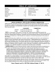
Warranty .................................. 2 Troubleshooting ............................ Safety Rules ............................... 3 Schematic/Wiring Diagram ................. 20-21 Replacement Parts ...................... 22-29 Assembly ............................... 4-5 Operation .............................. 6-12 Product Specifications ....................... 13 Maintenance ........................... 13-16 Storage ..................................
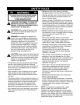
• Do Not use worn, bare, frayed or otherwise damaged electrical cord sets with the generator. The engine exhaust from this product contains chemicals known to the State of California to cause cancer, birth defects, or other reproductive harm. LOOK FOR THIS SYMBOL TO POINT OUT IMPORTANT SAFETY PRECAUTIONS. IT MEANS "ATTENTION!!! BECOME ALERT!!! YOUR SAFETY IS INVOLVED." • Operate generator only on level surfaces and where it will not be exposed to excessive moisture, dirt, dust or corrosive vapors.
Yourgeneratorrequiressomeassemblyandis ready foruseafterit hasbeenproperlyservicedwiththe recommended oilandfuel. • Remove the 4 battery tray screws from cradle. If you have any problems with the assembly of your generator, please call the generator helpline at 1-800-222-3136. IMPORTANT: Any attempt to run the engine before it has been serviced with the recommended oil will result in an engine failure. TO REMOVE CARTON GENERATOR FROM • Position the battery tray and install with supplied hardware.
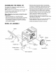
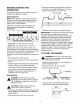
ASSEMBLING THE WHEEL KIT The wheel kit is designed to greatly improve the portability of your generator. NOTE: Wheel kit is not intended for over-the-road use. You will need a socket wrench with 1/2" or 13ram sockets to install the wheel kit. Refer to illustration shown below and install the wheel kit as follows: • Place the generator on a hard flat surface. • Stand at the engine end of the generator and gently tilt the generator forward, high enough to place wooden blocks beneath the cradle.
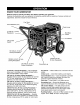
KNOW YOUR GENERATOR Read the owner's manual and safety rules before operating your generator Compare the illustrations with your generator to familiarize yourself with the locations of various controls and adjustments. Save this manual for future reference.
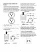
CORD SETS AND CONNECTOR PLUGS 120 Volt AC, 20 Amp, Duplex Receptacle This is a 120 Volt outlet protected against overload by a 20 Amp push-to-reset circuit breaker. Use each socket to power 120 Volt AC, single phase, 60 Hz electrical loads requiring up to a combined 2,400 watts (2.4 kW) or 20 Amps of current. Use only high quality, well-insulated, 3-wire grounded cord sets rated for 125 Volts at 20 Amps (or greater).
120/240 Volt AC, 50 Amp Receptacle HOW TO USE YOUR GENERATOR Use a NEMA 14-50 plug with this receptacle. Connect a 4-wire cord set rated for 250 Volts AC at 50 Arnps to the plug. If you have any problems operating your generator, please call the generator helpline at 1-800-222-3136. Grounding 240 Volts AC The Generator The National Electrical Code requires that the frame and external electrically conductive parts of this generator be properly connected to an approved earth ground.
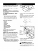
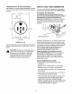
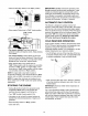
BEFORE STARTING GENERATOR THE • Slowly add unleaded regular gasoline to fuel tank. Be careful not to overfill. Allow about 1/2" of tank space for fuel expansion, as shown here. To operate the generator you will need to first add engine oil and gasoline, as follows: Add Engine 1/2" Air Space Tank Fuel Oil NOTE: When adding oil to the engine crankcase in the future, use only high quality detergent oil rated with API service classification SF or SG SAE 30 weight. Use no special additives.
Placethe Run/Stop Switchinthe"Run"position. IMPORTANT: Do Not overload the generator. Also, Do Not overload individual panel receptacles. These outlets are protected against overload with push-toreset-type circuit breakers. If amperage rating of any circuit breaker is exceeded, that breaker opens and electrical output to that receptacle is lost. Read "Don't Overload the Generator" on page 12 carefully. AUTOMATIC IDLE CONTROL This feature is designed to greatly improve fuel economy.
LOW OIL PRESSURE SYSTEM SHUTDOWN The engine is equipped with a low oil pressure that shuts down the engine automatically when pressure drops below 6 psi. If the engine shuts by itself and the fuel tank has enough gasoline, engine oil level. Your generator has the capability of recharging a discharged 12 Volt automotive or utility style storage battery. Do Not use the unit to charge any 6 Volt batteries. Do Not use the unit to crank an engine having a discharged battery.
DON'T OVERLOAD GENERATOR THE Overloading a generator in excess of its rated wattage capacity can result in damage to the generator and to connected electrical devices. Observe the following to prevent overloading the unit: • Some electric motors, such as induction types, require about three times more watts of power for starting than for running. This surge of power lasts only a few seconds when starting such motors.
MAINTENANCE SCHEDULE Follow the hourly or calendar intervals, whichever occurs first. More frequent service is required when operating in adverse conditions noted below.
• Coat gasket of new filter with engine oil. Turn filter _ AUTION! Neverinsert anyobjector tool clockwise until gasket contacts tightly with filter through theaircooling slots,evenif theengine adapter. Then tighten an additional 3/4 turn. is notrunning. NOTE:Do Notusea gardenhoseto cleangenerator. • Fill oil sump with recommended oil. (See "BEFORE STARTING THE GENERATOR" on page 9 for oil Watercanentertheenginefuelsystemandcause recommendations). problems.
SERVICE AIR CLEANER CLEAN Your engine will not run properly and may be damaged if you run it using a dirty air cleaner. Clean or replace the air cleaner paper filter once every 50 hours of operation or once a year, whichever comes first. Clean or replace more often if operating under dusty conditions. Clean foam precleaner every 25 hours of operation or sooner under dusty conditions. SPARK ARRESTOR SCREEN The engine exhaust muffler has a spark arrestor screen.
ADJUSTING VALVE CLEARANCE • When valve clearance is correct, hold the pivot ball stud in place with the allen wrench and tighten the rocker arm jam nut. Tighten the jam nut to 65-85 inch-pounds torque. After tightening the jam nut, recheck valve clearance to make sure it did not change. After the first 50 hours of operation, you should adjust the valve clearance in the engine.
GENERAL • While engine is still warm, drain oil from crankcase. Refill with recommended grade. The generator should be started at least once every seven days and allowed to run at least 30 minutes. If this cannot be done and you must store the unit for more than 30 days, use the following information as a guide to prepare it for storage. • Remove spark plug and pour about 1/2 ounce (15 ml) of engine oil into the cylinder. Cover spark plug hole with rag. Pull recoil starter slowly to distribute oil.
Problem Engine is running, but no AC output is available. Engine runs good but bogs down when loads are connected. Engine will not start; or starts and runs rough. Cause Solution 1. 2. 1. 2. 3. Circuit breaker is open. Poor connection or defective cord set. Connected device is bad. 4. Fault in generator. 4. 1. 2. Short circuit in a connected load. Generator is overloaded. 1. 2. 3. 4. Engine speed is too slow. Shorted generator circuit. 3. 4. 1. 2. 3. 4. Run/Stop switch set to Stop.
REGULATOR BOARD SCHEMATIC ii 22 44 o A T E s i 0 R A I 85 1 Y LOP IDLE SWITCH SWITCH RUN STOP P SPARK 50A 120V _SW \ 20A 44S TCH IGNITION 22 0 B, 22 llC BATTERY CHARGE i IB 6 7 +I2vI3A 13A _ START _oAcs\ e c K_'I L/#_ .........
ii IIA 44A BLU lIB ii IIA 44A _OA 35A 35A 20A lib 20A BOA 44A CB AUTO __CB RESET CB ? ] CB CB 15 L CD 120/240V CD 50A 120V/20A 12V/IOA DC IDLE 22 CONTROL 22 55 SWITCH 22 156 155 55 _2 _13 156 155 ] o J _ SYSTEM CONTROL BOARD GRN/YEL BLK I TRANSFORMER DLE CONTROL 2 PIN CONNECTOR WHT 44 ON BATTERY CHARGE I ......... __COIL SNUBBER FEEDBAC IDLE CONTROL • _ 2L_2J RB_LII_ 3 K BLK _ PIN WHTcToR_ J | l I ....... LF_ CONNE | _......
CRAFTSMAN Main Unit- 7500 Watt AC Generator 580.327182 Exploded View q/7 16 3 DETAIL OF ELECTRIC START SWITCH 9 TO STARTER 12 11 900_ 21 33 50 I 35 36 52 ,3 53 66 t I 64 69 39 .
CRAFTSMAN Main UnitItem 1 2 3 4 5 6 7 8 9 10 11 12 13 14 15 16 17 18 19 21 22 23 24 25 26 27 28 29 30 31 32 33 34 35 36 37 38 39 40 41 42 43 44 45 46 47 48 49 7500 Watt AC Generator 580.
CRAFTSMAN 7500 Watt AC Generator 580.327182 Wheel Kit -- Exploded View and Parts List Item 1 2 3 4 5 6 7 8 9 10 11 12 13 Pa_ # Qty B93393A 1 89742 2 93693A 1 87005 2 B89635 2 B93696 1 27007 2 42909 2 52858 8 22247 2 39253 2 22145 2 39287 4 Description HANDLE WHEEL AXLE PIN, Retaining SPACER, Wheel LEG, Support MOUNT, Vibration CAPSCREW, Hex Hd. M8 - 1.25 x 30 NUT, Lock M8 WASHER, Wheel CAPSCREW, Hex Hd. - M8 - 1.25 x 20 WASHER, Vibration Mtg. HHCS, M8 - 1.25 x 45 Lg GR 10.
CRAFTSMAN 7500 Watt AC Generator 580.327182 Control Panel -- Exploded View and Parts List 19 21 2O 19 25 \ 28 27 26 lO lO 14 11 18 17 28 12 15 27 17 18 15 24 7 8 11 / 16 18 17 5 12 4 Item 1 2 3 4 5 6 7 8 9 10 11 12 13 14 PaN # BB4461 23897 49226 91526 82538 82881 B4262 90418 75207N 75207A 75207 23365 68868 43437 Qty. 1 4 4 4 1 6 1 1 2 2 2 10 1 Description PANEL, Control WASHER, #10 M5 Flat WASHER, M5 Lock SCREW, M5-0.8 x 12 mm SWITCH, Idle Control WASHER, 7/16" Int.
Engine, GENERAC Power Systems, Low Oil Shutdown And Governor- Model EHF 00935 Exploded View 13 14 White / \ 15 8 16 \15 1 g White 4 / 10 24 25 / 23 21 \ 20 Item 7 8 9 10 12 13 14 15 16 Pa_ # 78653 85272 93104 93611 84329 92981 22097 92079 84542 Qty. 1 1 1 1 1 1 2 2 1 27 \ \ \ Item 20 21 23 24 25 27 28 29 30 Description Run/Stop Switch Led Assembly L.O.S. Decal Black Sleeving 3 Pin Male Hsg. Wire Asm.
Engine, GENERAC Power Systems, Low Oil Shutdown And Governor- Model EHF 00935 Exploded View 91 92 78 / 85 89 79 / / / / / / / < 8O / 82 56 85 / 81 87 \\ \. 85 Item 78 79 80 81 Part # 82774 91222C 67198N 67890 Qty. 1 1 1 1 Description Woodruff Key Flywheel w/Ring Gear Conical Washer M20 Hex Nut Item 82 83 84 85 86 87 88 89 90 91 92 Part # 88433 45756 78609 73104B 92437 88434 66476 96195 96196 73116A 81668 Qty.
Engine, GENERAC Carburetor, Power Systems, Air Cleaner, Oil Switch Model EHF 00935 and Oil Blockoff-Exploded View and Parts List 34 I 4O 31 33 61 6O 42 43 32- 45 44 38 36 4O 48 5O 35 51 49 45 37 38 Item 31 32 33 34 35 36 37 38 39 40 41 42 Part # 72745 91039 40945 81647 66476 91028 22097 49813 90970 93873 91204 89228 Qty. 1 1 2 2 2 1 3 2 1 2 1 1 Item 43 44 45 46 47 48 49 50 51 60 61 Description Breather Hose Head/Manifold Gasket M6 x 20 SHCS Carb.
Engine, GENERAC Power Systems, Long Block - Exploded Model EHF 00935 View and Parts List 25 52. _._. 46 15 14 h 6 36 < / 24 / 5 25 22 / 50 48 / 27 / / 5 _0/ < 30 28 54 53 / 42 20 r_ 7 < 51 29 _47 57 \\\ 38 / '\ '19 < 39 "\ ',\ \ 12 \\ \ 41 / 51 J ",, \\ .52 47 10 54 55 Item 1 Part # 71978 Qty.
Your Warranty Rights and Obligations Warranty Period The California Air Resources Board ("CARB") and Sears Roebuck and Co., USA, are pleased to explain the Emission Control System Warranty on your model year 2000 and later small off-road engine (engine). In California, new engines must be designed, built and equipped to meet the State's stringent anti-smog standards.
Garantia................................. Reglas deseguridad........................ Montaje............................... Operaci6n............................. Especificaciones delProducto................. GARANTIA LIMITADA 31 32 33-34 35-41 43 Mantenimiento .......................... 43-46 Almacenamiento ........................... 47 Reparacion deaverias ...................... 49 Garantia deEmisiones...................... 51 Comoordenarpartes...............
BUSQUE ESTE SIMBOLO PARA SEI_IALAR PRECAUCIONES DE SEGURIDAD IMPORTANTES. ESTE SIGNIFICA "iATENCION!!! iESTE ALERTA!!! SU SEGURIDAD ESTA EN PELIGRO." _ • Opere el generador enicamente en superficies niveladas y donde no se vaya a exponer a humedad excesiva, suciedad, polvo o vapores corrosivos. • La gasolina es altamente INFLAMABLE y sus vapores son EXPLOSIVOS. No permita que fumen, que existan llamas abiertas, chispas o calor a su alrededor cuando manipule gasolina.
Su generador requiere de cierto ensamble y estar& listo para ser usado despu6s de haberle dado un servicio adecuado con el aceite y el combustible recomendados. Coloque la bateria sobre el soporte. Sujete la bateria al soporte utilizando dos pernos en "J", dos arandelas de seguridad, dos arandelas planas y dos tuercas hexagonales. '\ Si tiene problemas con el montaje de su generador, por favor Ilame a la Linea de Ayuda del Generador al 1-800-222-3136.
MONTAJE DEL JUEGO DE RUEDAS • Coloque las ruedas (elemento 2) y las arandelas planas (elemento 10) en cada extremo del eje e inserte el pasador de retenci6n (elemento 4). Retire los bloques. El juego de ruedas est& disefiado para mejorar el transporte del generador. Necesitar& una Ilave de cubos con cubos de ½" o 13mm para instalar el juego de ruedas.
CONOZCA SU GENERADOR Lea este manual del propietario y las reglas de seguridad antes de operar su generador. generador para familiarizarse con la ubicaci6n de los diferentes controles y ajustes.
JUEGOS DE CORDONES Y ENCHUFES DEL CONECTOR Tomacorriente 20 Amperios Tomacorriente 30 Amperios Doble de 120 Voltios de 120/240 Voltios AC, Use un enchufe tipo NEMA L14-30P con este tomacorriente. Conecte un juego de cordones con conexi6n a tierra de 4 alambres al enchufe y a la carga que desee. El juego de cordones deber& tener una capacidad de 250 Voltios a 30 Amperios (o mayor). Utilice este tomacorriente para operar cargas de 120 Voltios AC, 60 Hz, monof&sicas que requieran hasta 3,600 vatios (3.
Tomacorriente 50 Amperios de 120/240 Por Io general, la conexi6n de un alambre de cobre trenzado No. 12 AWG (American Wire Gauge) a la aleta de conexi6n a tierra y a una barra de conexi6n a tierra de cobre o bronce (electrodo) proporciona una protecci6n adecuada contra las descargas el6ctricas. Sin embargo, los cSdigos locales pueden variar substancialmente. Consulte con un electricista local para conocer los requisitos de conexi6n a tierra de su &rea.
• Coloque el generador sobre una superficie nivelada. • El &rea limpia alrededor de aceite amarillo Ilena la tapa. Quite el aceite Ilena la tapa. • Llene lentamente motor con aceite por el aceite Ilena abrir hasta que el nivel de aceite sea al grano de derramar. • • PARA DARLE ARRANQUE MOTOR _ Instale aceite amarillo Ilena la tapa y el dedo aprieta seguramente. • Aseg6rese de que la unidad est& nivelada. • Abra la v&lvula del combustible.
Encienda la unidad y despu6s coloque la caja sobre ella. Asegerese de que exista un mfnimo de dos pies de separaci6n entre la parte abierta de la caja y el objeto m_s cercano. Para arranque manual: Agarre el mango del arrancador y halelo lentamente hasta que sienta cierta resistencia. Despu6s, hale la cuerda con un movimiento r&pido del brazo. Permita que la soga se devuelva lentamente. No deje que la soga se "devuelva r&pidamente" y golpee el arrancador.
PROCEDIMIENTO BATERIAS DE CARGA DE • Si la bateria est& equipada con tapas de desfogue, asegQrese de que est6n instaladas y apretadas. • Limpie los terminales de la baterfa si es necesario. • Conecte el enchufe conector del cable de carga de la baterfa al tomacorrientes del panel identificado con las palabras "12-VOLT D.C.". iPELIGRO! Las baterfas de acumuladores producen gas de hidr6geno explosivo cuando son recargadas.
NO SOBRECARGUE GENERADOR EL • Algunos motores el6ctricos, como los de inducci6n, requieren aproximadamente tres veces m&s vatios de poder para su arranque que para su funcionamiento. Esta onda irruptiva de poder dura tan solo unos segundos durante el arranque de dichos motores. AsegQrese de tener en cuenta este alto vatiaje de arranque cuando seleccione los dispositivos el6ctricos que va a conectar a su generador. 1. Calcule la cantidad de vatios necesarios para dar arranque al motor m&s grande. 2.
PROGRAMA DE MANTENIMIENTO Siga los intervalos horarios o de calendario, Io que ocurra primero. Se requiere de servicio con mayor frecuencia opere la unidad en las condiciones adversas descritas a continuaci6n.
NOTA: No recomendamos el uso de mangueras de jardin para limpiar el generador. El agua podria introducirse en el sistema de combustible del motor y causar problemas. Adem&s, si el agua se introduce al generador a trav6s de las ranuras para aire de enfriamiento, algo del agua quedar& retenida en los espacios vacios y grietas del aislamiento del devanado del estator y rotor.
PROPORCIONE SERVICIO DEPURADOR DE AIRE AL LIMPIE LA PANTALLA APAGACHISPAS Su motor no funcionar& correctamente y podria resultar dafiado si Io hace funcionar con un depurador de aire sucio. Limpie o reemplace el filtro de papel del depurador de aire cada 50 horas de operaci6n o una vez al afio, Io que suceda primero. Limpielo o reempl&celo m&s a menudo si la unidad funciona bajo condiciones de suciedad o polvo excesivo.
AJUSTE DE LA SEPARACION LAS VALVU LAS DE NOTA: Deber& sostener en posici6n la contratuerca del brazo oscilante a medida que gira el pasador de bola pivote. • Cuando la separaci6n de las v&lvulas sea la correcta, sostenga en posici6n el pasador de bola pivote con una Ilave allen y apriete la contratuerca del brazo oscilante. Apriete la contratuerca a un torque de 65-85 pulgadaslibras. Despu6s de apretar la contratuerca, vuelva a revisar la separaci6n de la v&lvula para cerciorarse de que no ha cambiado.
GENERALIDADES Haga funcionar el motor hasta que se detenga por la falta de combustible. El generador deber& ser encendido al menos una vez cada siete dias y deber& dejarlo funcionar al menos durante 30 minutos. Si no puede hacer esto y debe almacenar la unidad por m&s de 30 dias, siga las siguientes instrucciones para preparar su unidad para almacenamiento. Con el motor todavia caliente, drene el aceite de la caja del cigQefial. Vuelva a Ilenarlo con el grado de aceite recomendado.
Causa Problema El motor estd funcionando pero no existe salida de AC disponible. El motor funciona bien sin cargas pero "funciona mal" cuando las cargas son conectadas. El motor no arranca; o arranca y funciona mal. Solucibn 1. 2. Reajuste el cortacircuito. Revise y repare. 3. 4. Uno de los cotacircuitos est& abierto. Mala conexi6n o juego de cordones defectuoso. El dispositivo conectado est& en mal estado. Falla en el generador 1. 2. Corto circuito en la carga conectada.
Sus Obligaciones y Derechos servicio autorizado 1-800-473-7247. de Garantia La Junta Directiva de Recursos Ambientales de California ("CARB") y Sears Roebuck and Co. USA, tienen el gusto de explicar la Garantfa del Sistema de Control de Emisiones de su motor (motor) Periodo o mantenimiento inadecuado cuando sea necesario", sera garantizada por 2 afios.
For in-home major brand repair service: Call 24 hours a day, 7 days a week 1-800-4-MY-HOME Para pedir servicio de reparacibn sM(1-800-469-4663) a domicilio - 1-800-676-5811 In Canada for all your service and parts needs call - 1-800-665-4455 Au Canada pour tout le service ou les pieces For the repair or replacement parts you need: Call 7 am - 7 pm, 7 days a week 1-800-366-PART Para ordenar (1-800-366-7278) piezas con entrega a domicilio - 1-800-659-7084 For the location of a Sears Parts and Repair