
Owners manual


6
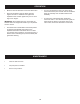
FIGURE 2
LIFT LEVER
ASSEMBLY
SLEEVE HITCH
FRAME ASSEMBLY
WELD
PIN
5/8" NYLOCK NUT
SPACER PLATE
(SEE NOTE)
HEX BOLT
5/8" x 1-3/4"
STEP 1: (SEE FIGURE 2)
• Hook the Sleeve Hitch Frame assembly onto the weld
pins. Attach the bottom of the assembly to the tractor
hitch using a 5/8" x 1-3/4" hex bolt and a 5/8" nylock
nut.
NOTE: If your tractor hitch has ridges that prevent the
sleeve hitch assembly from resting at, place the spacer
plate underneath the sleeve hitch assembly.
STEP 2: (SEE FIGURE 2)
• Proceed to LIFT ASSEMBLY instructions on page 8.
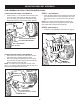
MOUNTING BRACKET ASSEMBLY
FIGURE 1A
3/8" HEX NUT
3/8" LOCK WASHER
LEFT MOUNTING BRACKET
3/8" x 1-1/4"
HEX BOLT
RIGHT MOUNTING BRACKET
IF YOUR TRACTOR LOOKS LIKE FIGURE 1A
• Install two 3/8" x 1-1/4" hex bolts in the left side of the
tractor as shown. Attach the Left Mounting Bracket
(pin at top facing in) to the bolts using two 3/8" lock
washers and 3/8" hex nuts. Repeat on the right side.
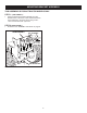
FIGURE 1B
ORIGINAL NUT
LEFT MOUNTING
BRACKET
3/8" FLAT WASHER
(TOP HOLE ONLY)
REMOVE NUTS
FROM BOLTS
RIGHT MOUNTING
BRACKET
3/8" LOCK WASHER
(If new bolt and nut are needed)
IF YOUR TRACTOR LOOKS LIKE FIGURE 1B
• Remove the nuts from the two bolts shown in each
side of the tractor, leaving the bolts in place.
• Attach the Left Mounting Bracket (pin at top facing
in) to the bolts using the original nuts and a 3/8" at
washer. Repeat for the other side.
NOTE: If no bolt and nut are present in a hole, use a
3/8" x 1-1/4" hex bolt, 3/8" lock washer and 3/8" hex nut to
attach the Mounting Bracket to the hole.
THIS ASSEMBLY IS FOR 917 TRACTOR MODELS ONLY.