Owner’s Manual Mini Multimeter with Non-Contact Voltage Detector (NCV) Model No. 82312 CAUTION: Read, understand and follow Safety Rules and Operating Instructions in this manual before using this product. ! Safety ! Operation ! Maintenance ! Español © Sears, Roebuck and Co., Hoffman Estates, IL 60179 U.S.A. www.craftsman.
TABLE OF CONTENTS Warranty............................................................................................ 3 Safety Instructions ............................................................................ 4 Safety Symbols ................................................................................. 5 Controls And Jacks........................................................................... 6 Symbols .........................................................................................
ONE YEAR FULL WARRANTY ONE YEAR FULL WARRANTY ON CRAFTSMAN MULTIMETER If this CRAFTSMAN Multimeter fails to give complete satisfaction within one year from the date of purchase, RETURN IT TO THE NEAREST SEARS STORE OR OTHER CRAFTSMAN OUTLET IN THE UNITED STATES, and Sears will replace it, free of charge. This warranty gives you specific legal rights, and you may also have other rights which vary from state to state. Sears, Roebuck and Co., Dept.
SAFETY INSTRUCTIONS This meter has been designed for safe use, but must be operated with caution. The rules listed below must be carefully followed for safe operation. 1. NEVER apply voltage or current to the meter that exceeds the specified maximum: Input Protection Limits Function Maximum Input V DC or V AC 600V AC and DC mA AC/DC 200mA DC/AC A AC/DC 10A DC/AC (for 30 seconds max. every 15 minutes) Resistance, Diode Test, Continuity 250V DC/AC 2. 3. 4. 5. 6. 7. 8.
SAFETY SYMBOLS This symbol adjacent to another symbol, terminal or operating device indicates that the operator must refer to an explanation in the Operating Instructions to avoid personal injury or damage to the meter. WARNING This WARNING symbol indicates a potentially hazardous situation, which if not avoided, could result in death or serious injury. CAUTION This CAUTION symbol indicates a potentially hazardous situation, which if not avoided, may result damage to the product.
CONTROLS AND JACKS 1. AC Voltage Detector Sensor 2. AC Voltage Detector indicator light 3. LCD display 4. Non-contact AC Voltage Detector test button 5. Rotary function dial 6. 10 ampere test lead jack 7. COM test lead jack 8. Test lead jack for voltage, milliamp, resistance/continuity, and diode functions 9.
SYMBOLS •))) Continuity Diode Battery status AC DC -3 m k V A ! milli (10 ) (volts, amps) 3 kilo (10 ) (ohms) Volts Amps Ohms AC DC Alternating current Direct current 7
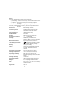
SPECIFICATIONS Function Range Resolution Accuracy Non100 to Resolution & accuracy do not apply since contact AC 600V the meter does not display the voltage in Voltage this mode. The lamp at the top of the detector meter’s display flashes when voltage is sensed and an audible warning will sound. DC Voltage 200mV 0.1mV (V DC) !(0.5% reading + 2 digits) 2000m 1mV V 20V 0.01V 200V 0.1V 600V AC Voltage 200V (VAC) 600V 50/60Hz !(1.0% reading + 2 digits) 1V !(1.5% reading + 2 digits) 0.1V !(1.
Notes: Accuracy specifications consist of two elements: • (% reading) – This is the accuracy of the measurement circuit. • (+ digits) – This is the accuracy of the analog to digital converter. o o o o Accuracy is stated at 65 F to 83 F (18 C to 28 C) and less than 75% RH. Diode Test Bias voltage: 2.
Safety UL LISTED This meter is intended for indoor use and protected, against the users, by double insulation per EN61010-1 and IEC61010-1 2nd Edition (2001) to CAT II 1000V & CAT III 600V; Pollution Degree 2. The meter also meets UL 61010-1, Second Edition (2004), CAN/CSA C22.2 No. 610101, Second Edition (2004), and UL 61010B-2-031, First Edition (2003) The UL mark does not indicate that this product has been evaluated for the accuracy of its readings.
BATTERY INSTALLATION WARNING: To avoid electric shock, disconnect the test leads from any source of voltage before removing the battery cover. 1. Disconnect the test leads from the meter. 2. Remove the rear battery cover by removing the two screws using a Phillips head screwdriver. 3. Insert the battery into battery clips, observing the correct polarity. 4. Put the battery cover back in place and secure with the two screws.
OPERATING INSTRUCTIONS WARNING: Risk of electrocution. High-voltage circuits, both AC and DC, are very dangerous and should be measured with great care. NOTE: On some low AC and DC voltage ranges, with the test leads not connected to a device, the display may show a random, changing reading. This is normal and is caused by the high-input sensitivity. The reading will stabilize and give a proper measurement when connected to a circuit.
NON-CONTACT AC VOLTAGE DETECTOR The EX310 can detect the presence of AC voltage (from 100 to 600VAC) simply by being held very near to a voltage source. WARNING: Test the AC voltage detector on a known live circuit before each use. WARNING: Before using the meter in the AC Voltage Detector mode, verify that the battery is fresh by confirming characters appear on the LCD when the function dial is turned to any position. Do not attempt to use the meter as an AC Voltage Detector if the battery is weak or bad.
AC VOLTAGE MEASUREMENTS WARNING: Risk of Electrocution. The probe tips may not be long enough to contact the live parts inside some 240V outlets for appliances because the contacts are recessed deep in the outlets. As a result, the reading may show 0 volts when the outlet actually has voltage on it. Make sure the probe tips are touching the metal contacts inside the outlet before assuming that no voltage is present. CAUTION: Do not measure AC voltages if a motor on the circuit is being switched ON or OFF.
DC VOLTAGE MEASUREMENTS CAUTION: Do not measure DC voltages if a motor on the circuit is being switched ON or OFF. Large voltage surges may occur that can damage the meter. 1. 2. 3. 4. Set the function switch to the highest VDC position. Insert the black test lead banana plug into the negative COM jack. Insert the red test lead banana plug into the positive V jack. Touch the black test probe tip to the negative side of the circuit. Touch the red test probe tip to the positive side of the circuit.
BATTERY VOLTAGE TEST CAUTION: Do not measure batteries while they are installed in the devices they are powering. The batteries must be removed from installations before tests can be made. 1. 2. 3. 4. Set the function switch to the 1.5V or 9V BAT switch position. Use the 1.5V position for ‘AAA’, ‘AA’, ‘C’, ‘D’, and other 1.5V batteries. Use the 9V position for square 9V transistor batteries. Insert the black test lead banana plug into the negative COM jack.
AC / DC CURRENT MEASUREMENTS CAUTION: Do not make current measurements at 10 Amps for longer than 30 seconds. Exceeding 30 seconds may cause damage to the meter and/or the test leads. 1. 2. 3. 4. 5. 6. 7. Insert the black test lead banana plug into the negative COM jack. For current measurements up to 200mA AC or DC, set the function switch to the 200m AAC or ADC position and insert the red test lead banana plug into the mA jack.
RESISTANCE MEASUREMENTS WARNING: To avoid electric shock, disconnect power to the unit under test and discharge all capacitors before taking any resistance measurements. 1. Set the function switch to the highest !! position. 2. Insert the black test lead banana plug into the negative COM jack. Insert the red test lead banana plug into the positive ! jack. Touch the test probe tips across the circuit or part under test.
CONTINUITY CHECK WARNING: To avoid electric shock, never measure continuity on circuits that have a voltage potential. 1. 2. 3. 4. 5. Set the function switch to the position. Insert the black lead banana plug into the negative COM jack. Insert the red test lead banana plug into the positive ! jack. Touch the test probe tips to the circuit or wire you wish to check. If the resistance is less than approximately 100!, the audible signal will sound. If the circuit is open, the display will indicate “1___”.
DIODE TEST 1. 2. 3. 4. 5. Set the function switch to the position. Insert the black test lead banana plug into the negative COM jack and the red test lead banana plug into the positive jack. Touch the test probes to the diode under test. A good diode will indicate approx. 700 ohms for the forward test and “1___” for the reverse test. A shorted diode will indicate the same value of resistance in both the reverse and forward test directions. An open diode will indicate “1___” in both test directions.
MAINTENANCE WARNING: To avoid electric shock, disconnect the test leads from any source of voltage before removing the back cover or the battery or fuse covers. WARNING: To avoid electric shock, do not operate your meter until the battery and fuse covers are in place and fastened securely. This MultiMeter is designed to provide years of dependable service, if the following care instructions are performed: 1. 2. 3. 4. 5. 6. KEEP THE METER DRY. If it gets wet, wipe it off.
BATTERY REPLACEMENT 1. Disconnect the test leads from the meter. 2. Remove the protective rubber holster. See diagram. 3. Remove the Phillips head screw located on the lower back of the instrument. 4. Remove the fuse/battery compartment cover to access the battery. See diagram. 5. Replace the 9V battery observing polarity. 6. Secure the fuse/battery compartment cover using the Phillips head screw. 7. Place the protective rubber holster on the meter. 2 1 5 3 4 6 1. Removable Rubber Holster 2. Meter 3.
REPLACING THE FUSES WARNING: To avoid electric shock, disconnect the test leads from any source of voltage before removing the fuse cover. 1. Disconnect the test leads from the meter. 2. Remove the protective rubber holster. 3. Remove the Phillips head screw located on the lower back of the instrument. 4. Remove the fuse/battery compartment cover to access the fuses. 5. Gently remove the fuse(s) and install new fuse(s) into the holder(s). 6.
TROUBLESHOOTING There may be times when your meter does not operate properly. Here are some common problems that you may have and some easy solutions to them. Meter Does Not Operate: 1. Always read all the instructions in this manual before use. 2. Check to be sure the battery is properly installed. 3. Check to be sure the battery is good. 4. If the battery is good and the meter still doesn’t operate, check to be sure that both ends of the fuse are properly installed.