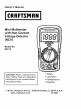
Owner's Manual Mini Multimeter with Non-Contact Voltage (NCV) Detector Model No. 82312 CAUTION: Read, understand and follow Safety Rules and Operating Instructions in this manual before • Safety using this product. • EspafioI O Sears, Roebuck and Co., Hoffman www.craftsman.com • Operation • Maintenance Estates, IL 60179 U.S.A.
IP'._:| II :[o] |o[o] _ I / :1_ i I_ Warranty ............................................................................................ Safety Instructions ............................................................................ Safety Symbols ................................................................................. Controls And Jacks ........................................................................... Symbols ..........................................................................
D]_ I=li'd =!':1t,I =1II I IlVlVl:l t,]tJ':l _i I_ ONE YEAR FULL WARRANTY ON CRAFTSMAN MULTIMETER If this CRAFTSMAN Multimeter fails to give complete satisfaction within one year from the date of purchase, RETURN IT TO THE NEAREST SEARS STORE OR OTHER CRAFTSMAN OUTLET IN THE UNITED STATES, and Sears wiii replace it, free of charge. This warranty gives you specific legal rights, and you may also have other rights which vary from state to state. Sears, Roebuck and Co., Dept.
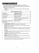
This meter has been designed for safe use, but must be operated with caution. The rules listed below must be carefully followed for safe operation. NEVERapplyvoltage or current to the meterthat exceedsthe specified maximum: Input Protection Function Limits Maximum Input V DC or V AC 600V AC and DC mA AC/DC 200mA DC/AC AAC/DC 10A DC/AC (for 30 seconds max. every 15 minutes) Resistance, Continuity Diode Test, 250V DC/AC 2. USEEXTREMECAUTIONwhenworking with high voltages. 3.
+.*I_1:11 Ik'dl,.'b'd _v+ I:[o] I!_ This symbol adjacent to another symbol, terminal or operating device indicates that the operator must refer to an explanation in the Operating Instructions to avoid personal injury or damage to the meter. L WARNING ] This WARNING symbol indicates a potentially hazardous situation, which if not avoided, could result in death or serious injury.
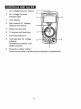
_o] _i / _To]iF.']r_*l_Ie]PF_*To_ [(_ 1. AC Voltage Detector Sensor 1 2. AC Voltage Detector indicator light z 3. LCD display 4. Non-contact AC Voltage Detector test button 5, Rotary function dial 6. 10 ampere test lead jack 7. COM test lead jack 8.
[(,.-._"d _vj I-[e] _-.] .
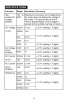
_'.,1_[l! IiI [___1t [.] __ Function Range Noncontact AC 100 to Resolution & accuracy do not apply since 600V the meter does not display the voltage in this mode. The lamp at the top of the meter's display flashes when voltage is sensed and an audible warning will sound. Voltage detector Resolution Accuracy DC Voltage 200mV 0.1 mV _+(0.5% reading + 2 digits) (V DC) 2000m V lmV 20V 0.01V 200V 0.1V 600V 1V _+(1.5% reading + 2 digits) AC Voltage (VAC) 50/60Hz 200V 0.1V _+(1.
Notes: Accuracy specifications consist oftwoelements: • (%reading) - Thisistheaccuracy ofthemeasurement circuit. • (+digits) - Thisistheaccuracy oftheanalog todigital converter. Accuracy isstated at65°F to83°F (18°C to28°C) andlessthan 75%RH. Diode Test Bias voltage: 2.3VDC Continuity Check Audible signal will sound if the resistance is less than 100£-.
Safety ULLISTED PER IEC1010 OVERVOLTAGE Thismeter isintended forindoor use andprotected, against theusers, by doubleinsulation perEN61010-1 andIEC61010-1 2ndEdition (2001) toCATII 1O00V & CATIII600V; Pollution Degree 2.Themeter also meets UL61010-1, Second Edition (2004), CAN/CSA C22.2 No.610101,Second Edition (2004), andUL 61010B-2-031, First Edition (2003) TheULmarkdoes notindicate that thisproduct hasbeenevaluated for theaccuracy ofitsreadings.
I from WARNING: an)/source To avoid of voltage electricbefore shock,removing disconnect the batter)/cover. the test leads 1. 2. 3. 4. I Disconnect the test leads from the meter. Remove the rear battery cover by removing the two screws using a Phillips head screwdriver. Insert the battery into battery clips, observing the correct polarity. Put the battery cover back in place and secure with the two screws.
I DC, are very dangerous and should be measured with great I and WARNING: Risk ofelectrocution. High-voltage circuits, both AC I care. NOTE: On some low AC and DC voltage ranges, with the test leads not connected to a device, the display may show a random, changing reading. This is normal and is caused by the high-input sensitivity. The reading will stabilize and give a proper measurement when connected to a circuit.
NON-CONTACT ACVOLTAGE DETECTOR TheEX310 candetect thepresence ofACvoltage (from100to 600VAC) simply bybeing heldverynear toavoltage source. WARNING: TesttheACvoltage detector onaknown livecircuit before each use. WARNING: Before using themeter intheACVoltage Detector mode, verify thatthebattery isfreshbyconfirming characters appear ontheLCD when thefunction dialisturned toany position. Donotattempt tousethemeter asanACVoltage Detector ifthebattery isweak orbad.
AC VOLTAGE MEASUREMENTS WARNING: Risk of Electrocution. The probe tips may not be long enough to contact the live parts inside some 240V outlets for appliances because the contacts are recessed deep in the outlets. As a result, the reading may show 0 volts when the outlet actually has voltage on it. Make sure the probe tips are touching the metal contacts inside the outlet before assuming that no voltage is present. CAUTION: Do not measure AC voltages if a motor on the circuit is being switched ON or OFF.
DC VOLTAGE MEASUREMENTS is being switched ON or OFF. Large voltage surges may occur CAUTION: Do not measure DC voltages if a motor on the circuit that can damage the meter. 1. 2. Set the function switch to the highest VDC position. Insert the black test lead banana plug into the negative COM jack. Insert the red test lead banana plug into the positive V jack. 3. Touch the black test probe tip to the negative side of the circuit. Touch the red test probe tip to the positive side of the circuit. 4.
BATTERY VOLTAGE TEST CAUTION: Do not measure batteries while they are installed in the devices they are powering. The batteries must be removed from installations before tests can be made. 1. Set the function switch to the 1.5V or 9V BAT switch position. Use the 1.5V position for 'AAA', 'AA', 'C', 'D', and other 1.5V batteries. Use the 9V position for square 9V transistor batteries. 2. Insert the black test lead banana plug into the negative COM jack.
AC / DC CURRENT MEASUREMENTS CAUTION: Do not make current measurements at 10 Amps for longer than 30 seconds. Exceeding 30 seconds may cause damage to the meter and/or the test leads. 1. Insert the black test lead banana plug into the negative COM jack. 2. For current measurements up to 200mA AC or DC, set the function switch to the 200m AAC or ADC position and insert the red test lead banana plug into the mA jack. 3.
RESISTANCE MEASUREMENTS WARNING: To avoid electric shock, disconnect power to the unit under test and discharge all capacitors before taking any resistance measurements. Set the function switch to the highest _2 position. 2. 3. Insert the black test lead banana plug into the negative COM jack. Insert the red test lead banana plug into the positive £-2jack. 4. 5. Touch the test probe tips across the circuit or part under test.
CONTINUITY WARNING: on circuits 1. 2. 3. CHECK To have avoid aelectric that voltage shock, potential,never measure continuity Set the function switch to the -I_ -)))position. Insert the black lead banana plug into the negative COM jack. Insert the red test lead banana plug into the positive £--)jack. 4. 5. Touch the test probe tips to the circuit or wire you wish to check. If the resistance is less than approximately 100£-.),the audible signal will sound.
DIODE TEST 1. Setthefunction switch tothe-I)l--)_ position. 2. Insert theblack testlead banana plugintothenegative COM jackandtheredtest leadbanana plugintothe positive -IN-jack. 3. Touch thetestprobes tothe diode under test. 4. Agood diode will indicate approx. 700 ohms for the forward test and "1 "for the reverse test. 5. A shorted diode will indicate the same value of resistance in both the reverse and forward test directions. An + open diode will indicate "1 in both test directions.
from any source of voltage before removing the back cover or J WARNING: To avoid electric shock, disconnect the test leads the battery or fuse covers. I until the battery and fuse covers are in place and fastened ARNING: To avoid electric shock, do not operate your meter securely. This MultiMeter is designed to provide years of dependable if the following care instructions are performed: 1. 2. 3. 4. 5. 6. service, KEEP THE METER DRY. If it gets wet, wipe it off.
',_-'_n n/d_I;_i'il;__I".,] if_,_ _I_v_ I_I_i 1. Disconnect the test leads from the meter. 2. Remove the protective rubber holster. See diagram. 3. Remove the Phillips head screw located on the lower back of the instrument. 4. Remove the fuse/battery compartment the battery. See diagram. cover to access 5. Replace the 9V battery observing polarity. 6. Secure the fuse/battery Phillips head screw. compartment cover using the 7. Place the protective rubber holster on the meter. 4 6 1.
REPLACING THE FUSES I from WARNING: To avoid electricbefore shock,removing disconnect the test leads any source of voltage the fuse cover. 1. Disconnect the test leads from the meter. 2. Remove the protective rubber holster. 3. Remove the Phillips head screw located on the lower back of the instrument. 4. Remove the fuse/battery the fuses. 5. Gently remove the fuse(s) and install new fuse(s) into the holder(s). 6.
/ ;(ellJ :] II :[_ -"[ele]l i I_[€ There may be times when your meter does not operate properly. Here are some common problems that you may have and some easy solutions to them. Meter Does Not Operate: 1. Always read all the instructions in this manual before use. 2. Check to be sure the battery is properly installed. 3. Check to be sure the battery is good. 4. If the battery is good and the meter still doesn't operate, check to be sure that both ends of the fuse are properly installed.
Manual del propietario # Mini multimetro con detector de voltaje sin contacto (VSC) Modelo No. 82312 PRECAUCION: Lea, comprenda y siga las Reglas Seguridad e Instrucciones de operaci6n en este manual antes de usar el producto. © Sears, Roebuck and Co., www.craftsman.com • • • • Seguridad Operaci6n Mantenimiento EspafioI Hoffman Estates, IL 60179 U.S.A.
Garantia Instrucciones de Seguridad Sefiales de Seguridad Controles y Conectores Sefiales Especificaciones Instalaci6n de la bateria Instrucciones de operaci6n Detector de voltaje CA sin contacto Medici6n de voltaje CA Medici6n de voltaje CD Prueba de voltaje de bateria Medici6n de corriente CA/CD Medidas de resistencia Verificaci6n de continuidad Prueba de diodo Mantenimiento Indicaci6n de bateria debil Reemplazo de la bateria Reemplazo de los fusibles Soluci6n de problemas Servicio y repuestos Pagina 3
GARANTiA TOTAL POR UN ANO EN EL MULTiMETRO CRAFTSMAN Si este multimetro CRAFTSMAN no le satisface totalmente dentro del primer a_o a partir de la fecha de compra, REGRt_SELO A LA TIENDA SEARS O DISTRIBUIDOR CRAFTSMAN M,_,S CERCANO EN LOS ESTADOS UNIDOS, y Sears Io reemplazar& sin cargos. Esta garantia la otorga derechos legales especificos, ademas de otros derechos variables entre estados que usted pueda tenet. Sears, Roebuck and Co., Dept.
k ( ok m _. m_,m Este medidor ha sido dise_ado para uso seguro, sin embargo debe ser operado con precauci6n. Para operar con seguridad debera cumplir las reglas enumeradas a continuaci6n. 1. NUNCAapliqueal medidorvoltaje o corrienteque excedalos limites m&ximosespecificados: Limites de protecci6n Funci6n Entrada de alimentaci6n m&xima V CD o V CA 600V CA y CD mA CA/CD 200mA CD/CA A CA/CD 10A CA/CD (durante 30 segundos max.
_ =1_P':_m=B,Im] l =1£,_ =[_u];._11 mT:_ m ± ADVERTENCIA I PRECAUCION F m m m 600V AX. Esta seSal adyacente a otra seSal, terminal o dispositivo en operaci6n indica que el usuario debera buscar la explicaci6n en las Instrucciones de operaci6n para evitar lesiones a su persona o daSos al medidor. Esta seSal de ADVERTENClA indica que J existe una condici6n potencialmente peligrosa, que si no se evita, podria resultar en la muerte o lesiones graves.
o[o]_i / _,[o]III:F._]k'|o[o]_I:[_ I[O]_,t:[_ 1, Sensor detector de voltaje CA 1 2 2. Luz indicadora del detector de voltaje CA 3 3. Pantalla LCD 4. Bot6n de prueba del detector de voltaje CA sin contacto 5, Perilla giratoria de funciones 6. Enchufe del cable de prueba de 10 amperios 7. Enchufe COM para cable de prueba 8. Enchufe para cable de prueba para funciones de voltaje, miliamperios, resistencia ! continuidad, y diodos 9.
=[,,,",) ",,,1 =[_]I_1[_I':__][e)_I=[_ Funci6n Escala Detector de 100 600V voltaje CA sin contacto Resoluci6n Voltaje CD 200mV 0.1mY (V CD) 2000m V 1mY 20V 0.01V 200V 0.1V 600V Voltaje CA (VCA) 50/60Hz Corriente CD ±(0.5%lectura + 2 digitos) ±(1.0%lectura + 2 digitos) 1V ±(1.5%lectura + 2 digitos) 200V 0.1V ±(1.5%lectura + 3 digitos) 600V 1V ±(2.0%lectura + 4 digitos 200mA 0.1mA ±(1.5%lectura + 2 digitos) 10A 0.01A ±(2.5%lectura + 5 digitos) 200mA 0,1mA ±(1.
Notas: Lasespecificaciones deprecisiSn consisten dedoselementos: • (%delectura) -Esta eslaprecisiSn delcircuito demedidas. •(+digitos) - PrecisiSn delconvertidor analSgico adigital. LaprecisiSn estaespecificada de18°C a28°C (65°F a83°F) y menos de75%HR. Prueba dediodo Voltaje depolarizaciSn: 2.3VCD Verificaci6n decontinuidad Seemitira unaseSal audible sila resistencia esmenor a 100£-.
Aprobaci6n CE, UL Seguridad este medidor es para uso en interiores y protegido, contra usuarios, por doble aislante conforme a EN61010-1 y IEC61010-1 2° Edici6n (2001) para CAT II 1000V y CAT III 600V; Grado de contaminaci6n 2. El medidor ademas cumple con UL 61010-1, Segunda edici6n (2004), CAN/CSA C22.2 No. 61010-1, Segunda edici6n (2004), y UL 61010B.-2-031, Primera edici6n (2003) La marca UL no indica que este producto ha sido evaluado en cuanto a la precisi6n de sus lecturas.
I deprueba decualquier fuente devoltaje antes dequitar I cables ADVERTENClA: Para evitar choque electrico, desconecte los la tapa de la bateria. 1. 2. 3. 4. Desconecte los cables de prueba del medidor. Quite los dos tomillos de la tapa posterior (B) con un destomillador Phillips. Inserte la bateria en el porta bateria, observando la polaridad correcta. Coloque la tapa de la bateria en su lugar y asegure con los dos tomillos.
_. i _ O_. II O" __A O_. iesoodee,ect I tensidn, tanto de CA g CD, son mug peligrosos medidos con gran cuidado. g deberan ser NOTA: En algunas escalas bajas de voltaje CA g CD, sin estar los cables de prueba conectados a dispositivo alguno, la pantalla puede mostrar una lectura aleatoria cambiante. Esto es normal g es causado por la alta sensibilidad de la alimentacidn. La lectura se estabilizara g data una medida apropiada al estar conectada a un circuito.
MEDICION DE VOLTAJE CA ADVERTENCIA: Riesgo de electrocuci6n. Las puntas de las sondas pueden no ser suficientemente largas para hacer contacto con las partes vivas dentro de algunos contactos 240V para electrodomesticos debido a que dichos contactos estan muy adentro de la caja. Como resultado, la lectura puede indicar 0 voltios cuando en realidad el contacto si tiene tensi6n.
MEDICION DE VOLTAJE CD esta encendiendo y apagando. Pueden ocurrir grandes oleadas PRECAUCION: No mida voltajes CD si un motor en el circuito de voltaje que daSarian al medidor. 1. 2. Fije el selector de funci6n en la posici6n VCD mas alta. Inserte el conector banana del cable negro de prueba en el enchufe negativo COM. Inserte el conector banana del cable rojo de prueba en el enchufe positivo V. 3. Toque la punta de la sonda negra de prueba del lado negativo del circuito.
PRUEBA DE VOLTAJE PRECAUCION: DE BATERiA No medir baterias mientras esten en los dispositivos que alimentan, Debe quitar su instalaci6n antes de realizar las pruebas, 1. Fije el selector de funci6n en la posici6n 1.5V o 9V BAT. Use la posici6n 1.5V para baterias 'AAA', 'AA', 'C', 'D' y otras de 1.5V. Use la posici6n 9V para baterias cuadradas de 9V para transistores. 2. Inserte el conector banana del cable negro de prueba en el enchufe negativo COM.
MEDICION DE CORRIENTE CA/CD durante mas de 30 segundos. Exceder 30 segundos puede I PRECAUCION: No tome y/o medidas de corriente sobre 10A causar dafios al medidor a los cables de prueba. 1. Inserte el conector banana del cable negro de prueba en el enchufe negativo COM. 2. Para medidas de corriente hasta 200mA CD o CA, fije el selector de funci6n en la posici6n 200m ACD o ACA e inserte el conector banana del cable rojo de prueba en el enchufe mA. 3.
MEDIDAS DE RESISTENCIA ADVERTENCIA: Para evitar choque electrico, desconecte la tensiSn a la unidad bajo prueba y descargue todos los capacitores antes de tomar cualquier medidas de resistencia. 1. Fije el selector de funciSn a la posiciSn £-._mas alta. 2. Inserte el conector banana del cable negro de prueba en el enchufe negativo COM. 3. Inserte el conector banana del cable rojo de prueba en el enchufe positivo £-._. 4. Toque las puntas de las sondas a traves del circuito o parte bajo prueba.
VERIFICACION DE CONTINUIDAD ADVERTENClA: Para evitar choque electrico, nunca mida continuidad en circuitos que tengan voltaje potencial. 1. Fije el selector de funci6n en la posici6n _-))). 2. Inserte el conector banana del cable 3. 4. 5. negro de prueba en el enchufe negativo (COM. Inserte el conector banana del cable rojo de prueba en el enchufe positivo £-2. Toque las puntas de las sondas al circuito o alambre que desee probar.
PRUEBA DE DIODO 1. 2. Fije el selector de funci6n en la posici6n -IN-))). Inserte el conector banana del cable negro de prueba en el enchufe negativo COM y el conector banana del cable rojo de prueba en el enchufe positivo -IN. 3. 4. Toque las puntas de las sondas al diodo bajo prueba. Un diodo bueno indicara aproximadamente 700 ohmios para la prueba hacia adelante y "1i" para la prueba en reversa. 5. Un diodo en corto indicara el mismo valor de resistencia en -- ambas direcciones de prueba.
,v_ !'__1 _IIII_1_II_V_l I_1_IIl[O cables de prueba de cualquier fuente de voltaje antes de quitar I la DVERTENClA: evitar desconecte los tapa posterior oPara la tapa de choque la bateriaelectrico, o fusibles. choque no opere medidor a menos que la tapa posterior y la tapa de la bateria y I ADVERTENCIA: Para evitar electrico, el fusibles esten colocadas y aseguradas.
1.Desconecte loscables deprueba delmedidor. 2.Quite lafunda protectora dehule. Veaeldiagrama. 3.Quite eltornillo cabeza Phillips Iocalizado enlabase posterior delmedidor. 4.Quite latapadelcompartimiento debaterias para alcanzar labateria. Veaeldiagrama. 5.Remplace labateria de9Vobservando lapolaridad. 6.Asegure latapadelcompartimiento delabateria/fusible coneltornillo cabeza Phillips. 7.Coloque lafunda protectora dehuleenelmedidor. 5 3 1. Funda de hule removible 2. Medidor 3. Bateria 4. Fusibles 5.
REEMPLAZO DE LOS FUSIBLES cables de prueba de cualquier la tapa de fusibles. fuente los cables de voltaje antes de prueba de quitar 1. Desconecte 2. Quite la funda 3. Quite el tornillo cabeza posterior del medidor. 4. Quite la tapa del compartimiento alcanzar los fusibles. 5. Suavemente quite los fusibles e instale los fusibles nuevos en el porta fusibles. 6.
.'-[o]lu[e,][o]_II m]:11:,ir,{o]:] ml:l,v_ r.,_ Habra ocasiones en que su medidor no funcione correctamente. En seguida encontrara algunos problemas comunes que puede Ilegar a tener y algunas soluciones faciles. El medidor no funciona: 1. Siempre lea todas las instrucciones en este manual antes de usar. 2. Revise que la bateria esta bien instalada. 3. Revise que la bateria tenga buena carga. 4.