
Owner's Manual


16
ASSEMBLY
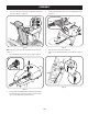
9. Make sure the shift lever on the back of the transmission is rotated
downward to the full extent of its rotation. See Figure 32.
Figure 32
10. Insert ferrule into top hole of shift lever and secure with cotter pin (a) and
washer (b) removed in Step 8. See Figure 31. Ferrule may need to be adjusted
up or down.
STOP
Continue to Set-Up (page 18).
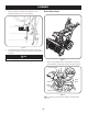
Electric Chute Control
Figure 33
1. Remove cotter pin, wing nut, and hex screw from chute control head and
clevis pin and bow-tie cotter pin from chute support bracket. See Figure 34.
Chute Control Head
Chute
1
1
2
Chute
Support
Bracket
Chute Base
Figure 34
NOTE: For smoothest operation, the cables should all be to the left of the chute
control rod.