® MODEL NUMBER 917.250480 OWNER'SMANUAL Assembly Operation o Customer Responsibilities o Service and Adjustments Repair Parts CAUTION: Read and follow FOR CONSUMER ! II all safety ASSISTANCE rules and instructions before operating HOT LINE, CALL THIS TOLL FREE NUMBER: IIIIIHIIIIIIII I I IIIIIIrllllll/llllllllllllllllrlrllll this equipment.
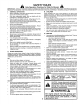
& SAFETY Practices RULES for Ride-On Safe Operation Mowers IMPORTANT: THIS CUTTING MACHINE IS CAPABLE OF AMPUTATING HANDS AND FEET AND THROWfNG OBJECTS. FAILURE TO OBSERVE THE FOLLOWING SAFETY INSTRUCTIONS COULD RESULT IN SERIOUS INJURY OR DEATH. I. GENERAL o Read, understand, and follow all instructions in the manual and on the machine before starting.
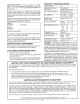
PRODUCT CONGRATULATIONS on your purchase of a Sears Tractor. It has been designed, engineered and manufactured to give you the best possible dependability and performance. Should you experience any problem you cannot easi{y remedy, please contact your nearest Sears Authorized Service Center/Department. We have competent, welltrained technicians and the proper tools to service or repair this tractor. Please read and retain this manual.
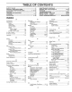
TABL SAFETY PRODUCT RULES SPEC_ ............................................................ FICAT|ONS OF CONTENTS MAINTENANCE SCHEDULE ..................................... 18 SERVICE AND ADJUSTMENTS ........................... 20-26 STORAGE ................................................................... 27 TROUBLESHOOTING ........................................... 28-29 REPAIR PARTS - TRACTOR ................................ 32=49 REPAIR PARTS - ENGINE ....................................
ACCESSORIES These accessories Most Sears stores and attachments can order these AND ATTACH were available through most Sears retail outlets and service centers items for you when you provide the model number of your tractor. when the tractor was purchased. MAINTENANCE ENGWNE SPARK E TS PLUG ENGINE OIL GAS CAN FUEL STABiLiZER AIR FILTER BLADES BELTS 2 PERFORMANCE Sears offers a wide variety of attachments that fit your tractor.
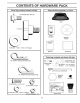
CONTENTS Parts Bag contents OF HARDWAR shown fuit size PACK Parts packed separately in carton (1) Shoulder Bolt 5/16-18 Seat (1) Knob Video Cassette (1) Washer 17/32 x !-3/!6 Steering Wheel f x 12 Gauge Manual Pads Bag Parts bag contents (3) Retainer Springs (double loop) z (2) Shoulder Bolts _(2) (4) Retainer Springs (single loop) \ not shown -\, fui! size (2) Washers 3/8 x 7/8 x 14 Gauge 12)Gauge Wheels Q Front Link Assemblies Steering Wheel Insert (2) Centerlock Nuts :_ (2) K
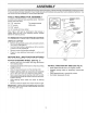
ASSEMBLY Your new tractor has been assembled at the factory with the exception of those parts left unassembled for shipping purposes. To ensure safe and proper operation of your tractor all parts and hardware you assemble must be tightened securely. Use the correct tools as necessary to insure proper tightness. TOOLS REQUSRED FOR ASSEMBLY A socket wrench set will make assembly easier, Standard wrench sizes are listed.
ASSEM CONNECT BATTERY (See Fig. 2) LY iNSTALL SEAT (See Fig. 3) Adjust seat before tightening adjustment knob. nals. Before connecting battery, remove meta!Do bracelets, wristwatch CAUT!_ON: not short battery termibands, rings, etc, _ Positive terminal must be connected first to prevent sparking from accidental grounding. o Lift hood to raised position.
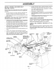
ASSEM INSTALL MOWER AND DRIVE LY Connect anti-sway bar to chassis bracket under left footrest and retain with double loop retainer spring. BELT (See Figs= 4 and 5) Turn height adjustment knob clockwise slack from mower suspension. Be sure tractor is on level surface and mower suspension arms are raised with attachment lift control. Engage parking brake. = Cut and remove tie down securing anti-sway bar. Swing anti-sway bar to left side of mower deck.
ASS CHECK TiRE MBLY PRESSURE CHECKL/S The tires on your tractor were overinflated at the factory for shipping purposes. Correct tire pressure is important for best cutting performance. BEFORE YOU OPERATE AND ENJOY YOUR NEW TRACTOR, WE WISH TOASSURE THAT YOU RECEIVE THE BESTPERFORMANCEAND SATISFACTION FROM THIS QUALITY PRODUCT.
OP ATIO These symbols may appear on your product or in literature supplied with the product. Learn and understand their meaning.
OPERATIC KNOW YOUR TRACTOR READ THiS OWNER'S MANUAL AND SAFETY RULES BEFORE OPERATING YOUR TRACTOR Compare the i_tustrations with your tractor to familiarize yourself with the locations of various controls and adjustments. this manuat for future reference.
OPERATION HOW TO USE YOUR TRACTOR TO SET PARKING BRAKE NOTE: Under certain conditions when tractor is standing idle with the engine running, hot engine exhaust gases may cause "browning" of grass. To eliminate this possibility, always stop engine when stopping tractor on grass areas. (See Fig. 6) Your tractor is equipped with an operator presence sensing switch. When engine is running, any attempt by the operator to leave the seat without first setting the parking brake wil! shut off the engine.
OPERATION TO ADJUST GAUGE WHEELS TO OPERATE (See Fig. 7) ON HILLS Adjust gauge wheels with tractor on a fiat level surface. o - Adjust mower to desired cutting height. Lower mower with lift control. Remove rear retainer spring and clevis pin which secure each gauge wheel. , Lower gauge wheels to ground. Raise gauge wheels slightly to align holes in bracket and gauge wheel bar and insert clevis pins, Gauge wheels should be slightly off the ground.
OPERATION ADD GASOLINE MOWING o o Fill fuel tank. Use fresh, clean, regular unleaded gasoline. (Use of leaded gasoline will increase carbon and lead oxide deposits and reduce valve life). iMPORTANT: WHEN OPERATtNGtNTEMPERATURES BELOW 32°F(0°C), USE FRESH, CLEAN WINTER GRADE GASOLINE TO HELP INSURE GOOD COLD WEATHER STARTING. Use the runner on the right hand side of mower as a guide. The blade cuts approximately an inch outside the runner (See Fig. 8).
CUSTO MAINTENANCE E ESPO ILITIE SCHEDULE FILL tN DATES AS YOU COMPLETE REGULAR SERVICE SERVICE Check Brake Operation Check Tire Pressure DATES Check for Loose Fasteners Sharpen/Replace Lubrication Check Mower Blades Chart Battery Level/Recharge Clean Battery and Terminals Check Transaxle Adjust Blade Adiust Motion Drive Belt(s) Tension Check Engine Change Cooling Be_t(s) Tension Oil Level Engine Oi! Clean Air Filter Clean Air Screen Inspect Replace Muffler/Spark Clean Eng
CUSTOM ESPONSIBILITIES TRACTOR The blade can be sharpened with a file or on a grinding wheel. Do not attempt to sharpen while on the mower. Atways observe safety rules when performing any maintenance. BRAKE o OPERATION If unit requires more than six (6) feet stopping distance at high speed in highest gear, then brake must be adjusted. (See "TO ADJUST BRAKE" in the Service and Adjustments section of this manual).
CUSTOM ESPONS Change the oil after the first two hours of operation and every 50 hours thereafter or at least once a year if the tractor is not used for 50 hours in one year. BATTERY Your tractor has a battery charging system which is sufficient for normal use. However, periodic charging of the battery with an automotive charger wi!l extend its life. • Keep battery and terminals clean. • Keep battery bolts tight.
CUSTO CLEAN AIR SCREEN ESPO ILJTIES (See Fig. 16) Air screen must be kept free of dirt and chaff to prevent engine damage from overheating. Clean with a wire brush or compressed air to remove dirt and stubborn dried gum fibers. ENGINE COOLING FINS (See Fig. !6) Remove any dust, dirt or oiI from engine cooling fins to prevent engine damage from overheating. Engine b!ower housing must be removed.
SERVICE CAUTION: o ,, o * D ADJ BEFORE PERFORMUNG ANY SERVICE OR ADJUSTMENTS: TO LEVEL MOWER MOWER (See Fig. 19) Place attachment clutch in "DISENGAGED" position. Turn height adjustment knob to lowest setting. Lower mower to its lowest position. Remove retainer spring holding anti-swaybar to chassis bracket and disengage anti-swaybar from bracket. o Remove _etainer springs from suspension arms at deck and disengage arms from deck. • Raise attachment lift to its highest position.
SERVICE A ADJUSTMENTS TO REPLACE FRONT-TO-BACK ADJUSTMENT (See Figs. 21 and 22)iMPORTANT: DECK MUST BE LEVEL SiDE-TO-SIDE. IF THE FOLLOWING FRONT-TO-BACK ADJUSTMENT !S NECESSARY, BE SU RE TO ADJUST BOTH FRONT LINKS EQUALLY SO MOWER WILL STAY LEVEL SIDE-TO-SIDE. To obtain the best cutting results, the mower housing should be adjusted so the front is approximately 1/8" to 1/2" lower than the rear when the mower is in its highest position. Check adjustment on right side of tractor.
SERVICE AN TO REPLACE (See Fig. 24) MOWER BLADE DRIVE ADJUSTMENTS BELT ROTOR k Park the tractor on level surface. Engage parking brake. Remove mower drive belt (See"TO REPLACE MOWER DRIVE BELT" in this section of this manual). • Remove mower (See "TO REMOVE MOWER" in this section of this manual). Remove four screws from R.H. mandrel cover and remove cover. Unhook spring from bolt on mower housing. • Carefully roll belt off R.H. mandrel pulley.
SERVICE AN TO REPLACE ADJUSTMENTS MOTRON DRIVE BELT TO ADJUST (See Fig. 27) Engage parking brake (creates slack in belt). - Remove mower drive belt from electric clutch pulley only (See "TO REPLACE MOWER DRIVE BELT" in this section of this manual). o Roll motion drive belt off transaxle putley. • Roll belt off clutching idler pulleys, then off engine pulley and front V-idler pulley.
SERVICE AND ADJUSTM TO REMOVE WHEEL NTS FOR REPAIRS FRONT WHEEL (See Fig. 30) . Block up axle securely. o Remove axle cover, retaining d ng and washers to allow wheel removal "POSITIVE" __ "NEGATIVE" (+) Repair tire and reassemble. ° Replace washers and snap retaining ring securely in axfe groove. o Replace axle cover. (-) WASHERS O RETAINING AXLE PANEL BOLT RING _\\ COVER\ FiG. 30 FIG. 31 REAR WHEELBlock rear axle securely. = Remove five (5) hub bolts to allow wheel removal.
RVICE AN TO ADJUST {See Fig, ATTACHMENT ADJ LiFT SPRING ADJUSTMENT 32) ° While holding spring bushing with wrench, loosen jam nut. ° Turn adjustment bolt clockwise to extend spring and reduce lift effort (for heavier attachments), , Turn adjustment tachments. bolt counterclockwise HOOD AND GRILL SPRING BUSHING for lighter atJAM Retighten jam nut against spring bushing. IMPORTANT: DO NOT ADJUST FOR MAXIMUM SPRING TENSION WHEN USING LIGHT ATTACHMENTS SUCH AS A MOWER.
SERVICE A ADJUSTMENTS ACCELERATION ENGINE TO ADJUST THROTTLE (See Fig. 34 and 35} CONTROL = CABLE The throttle control has been preset at the factory and adiustment should not be necessary. Check adjustment as described below before _oosening cable, if adjustment is necessary, proceed as follows: • With engine not running, move throttle control lever to fast (_) position. o Check that speed control lever is against stop screw.
STORAGE ENGINE Immediately prepare your tractor for storage at the end of the season or if the tractor will not be used for 30 days or more. FUEL SYSTEM IMPORTANT: IT IS IMPORTANT TO PREVENT GUM DEPOSITS FROM FORMING IN ESSENTIAL FUEL SYSTEM PARTS SUCH AS CARBURETOR, FUEL FILTER, FUEL HOSE, OR TANK DURING STORAGE. ALSO, EXPERIENCE INDICATES THAT ALCOHOL BLENDED FUELS (CALLED GASOHOL OR USING ETHANOL OR METHANOL) CAN ATTRACT MOISTURE WHICH LEADS TO SEPARATION AND FORMATION OF ACIDS DURING STORAGE.
TROUBLESHOOTI PROBLEM CAUSE Will not start 1. 2, 3. 4, 5. 6. 7. CORRECTION 1, Fil! fue! tank, properly. 2. 3. 4, 5, 6. 7, 8, 9. 10, Looseor damaged widng, Carburetor out of adjustment. Engine valves out of adjustment, 8. 9, t0. See "TO START ENGINE" in Operation section, Wait several minutes before attempting to start, Replace spark plug, Clean/replace air filter, Replace fuel filter, Drain fue! tank and carburetor, refill tank with fresh gasoline and replace fuet filter, Check all wiring.
TROUBLESHOOTING PROBLEM Engine continues to run when operator leaves seat with attachment clutch CORRECTION CAUSE 1. Faulty operator-safety 1. 2. POINTS presence control system. 1. Check wiring, switches and connections. If not corrected, contact an authorized service center/ department. Worn, bent or _oose blade. Mower deck notlevet. 1, 2. Replace blade. Tighten blade bolt. Level mower deck. 3. 4. 5. Buildup of grass, Ieaves, and trash under mower.
RVICE 3O OTE
TRACTOR - MODEL NUMBER 917.250480 SCHEMATIC REO AMMETER D WHITE E i SEATSW,TOH O7 i f BLACKSWITCH (NOT OCCUPIED BLACK D PTO (DISENGAGED) -1 1 GROUNDING CONNE(;TOR Q L_ BLACK [ IGNITION UNIT _ D SPARK PLUGS CHARGING SYSTEM OUTPUT 15 AMP DC @ 3600 RPM A RED l 28 VOLTS AC @ 36t)D RPM {REGULATOR DISCONNECTED) ORANGE fI_.
REPAIR PARTS TRACTOR - MODEL NUMBER 917.
REPAIR PARTS TRACTOR = MODEL NUMBER 917.
REPAIR PARTS TRACTOR CHASSIS - MODEL NUMBER 917.250480 AND ENCLOSURES 10 9 18 38 15 / 59 9 9 13 11 92 53 57 68 8 _, 37 47120 5 / 48 / 68 41 _.
REPAIR PARTS TRACTOR CHASSIS KEY NO. 1 2 3 4 5 6 7 8 9 10 11 12 13 14 15 16 17 18 I9 20 21 22 24 26 28 29 30 31 32 33 34 35 36 37 38 39 40 41 - MODEL NUMBER 917.250480 AND ENCLOSURES PART NO.
REPAIR PARTS TRACTOR GROUND - MODEL NUMBER 917o250480 DRIVE 44 29 : 68 64 37 51 38 65 53 48 54 57 22 24 62 36 66
REPAIR PARTS TRACTOR GROUND KEY NO. PART NO, 1 3 4 5 6 7 8 9 I0 1t t2 13 t4 15 16 17 18 19 21 22 23 24 25 26 27 9858MI 7563R 17490508 73680600 76020412 135758 12000034 140080 142509 136927 9204H 139419 138901 19131316 143012 !26909X 137104 136926 23260412 633A109 106932X 136925 136923 137552 17490528 28 29 30 34 35 36 37 73350600 137213 19131614 t24236X 137648 138364 121749X = MODEL NUMBER 917.250480 DRIVE KEY NO, DESCRmPTION Key, Woodruff Washer, Thrust, Axle Screw, Thdrot.
REPAIR PARTS TRACTOR STEERING - MODEL NUMBER 917.
REPAIR PARTS TRACTOR STEERING - MODEL NUMBER 917.250480 ASSEMBLY KEY NO.
REPAIR PARTS TRACTOR ENGnNE o MODEL NUMBER 9!7,250480 30 20 62 36, 32 35 2 39 24 39 / 12 14 18 11 15 _j4 17 @ L=,.
REPAIR PARTS TRACTOR - MODEL NUMBER 917.250480 ENGINE KEY NO. 1 2 PART NO.
REPAIR PARTS TRACTOR .. MODEL NUMBER 917.250480 SEAT ASSEMBLY 5 t9 17 KEY NO. PART NO. 1 2 3 4 5 6 7 8 9 10 12 13 140124 140551 140675 I27018X 145006 73680600 124181X 17490508 19131614 140552 121246X t21248X 12 KEY NO. DESCRIPTION Seat Bracket, Pivot Seat Strap, Fender Bolt, Shoulder 5/16-!8 x .62 Clip, Push In Hinged Nut, Crownlock 3/8-16 Unc Spring, Seat Cprsn Screw, Thdrot 5/16-18 X 1/2 Washer 13/32 X 1 X 14 Ga.
REPAIR PARTS TRACTOR =- MODEL NUMBER 917.250480 DECALS 18 6 3 7 15 15 8 13 7 4 13 \ 1t 10 12 !4. 16 KEY NO. 1 2 3 4 5 6 7 8 9 10 11 12 PART NO.
"MODEL NUMBEF_ 917.
REPAIR PARTS TRACTOR - MODEL NUMBER 917.250480 LiFT ASSEMBLY KEY NO, 1 2 3 4 5 6 7 8 9 t0 I1 12 13 14 15 I6 17 18 19 20 21 22 23 24 25 26 27 28 29 30 31 32 33 34 35 36 37 38 39 40 41 42 43 PART NO.
REPAIR PARTS TRACTOR MOWER = MODEL NUMBER 917.250480 DECK 55 48 48 60 ÷ 36 2 !/9 3 20!.
REPAIR PARTS TRACTOR MOWER = MODEL NUMBER 917.250480 DECK KEY NO. PART NO. 1 2 3 4 5 6 7 8 9 !0 11 12 t3 140579 73680500 72110506 7631J 138457 4939M 130832 850857 10030600 140296 130652 129895 137553 14 15 16 17 18 t9 20 2t 22 23 24 25 27 28 30 3! 32 33 34 137152 110485X 140329 106735X 19111016 105304X 1237!3X 137607 110452X 109785X 136321 19111216 19131316 132823 138776 137266 129861 129963 72140610 KEY NO, DESCRIPTION Deck Asm.
REPAmR PARTS 'TRACTOR ° MODEL NUMBER 9!7.
REPAIR PARTS TRACTOR - MODEL NUMBER 917o250480 TRANSAXLE KEY PART NO.
REPAmR PARTS TRACTOR KOHLER ENGINE - MODEL NUMBER - MODEL NUMBER NIV18S, TYPE NUMBER 9!7.250480 58560 / 8 7 l % / 6 --g BREATHER AND VENT t0 --11 _12 18 .
REPAIR PARTS TRACTOR KOHLER ENGJNE = MODEL NUMBER = MODEL NUMBER MVlBS, TYPE NUMBER AiR iNTAKE KEY PART NO. NO, 1 2 X-276_7 52 755 83 3 4 5 6 7 8 9 I0 52 096 35 52 !23 2! 231032 52 082 04 45 083 0! 45 083 02 237423 X_67-98 11 12 13 14 15 52 20t 06 277093 52 054 39 X-25-79 X-50-37 16 X-50-57 17 X-22-9 18 25 041 06 917.
REPAIR PARTS TRACTORKOHLER ENGINE = MODEL NUMBER MODEL MV18S, NUMBER TYPE NUMBER 9!7,250480 58560 19 ....... 13 _ 3_ 6 @_ _'-_ i 5 11 52 12 .
REPAIR PARTS TRACTOR KOHLER ENGINE - MODEL NUMBER o MODEL NUMBER MV18S, TYPE NUMBER CRANKCASE KEY PART NO. NO. 1 2 3 X-82-2 52 468 12 82 755 16 4 5 6 7 8 52 016 05 52 031 01 52 316 06 52 755 50 5207212 9 10 11 12 !3 25 086 12 X-269-43 52 078 05 52 030 10 52 030 11 52 030 12 25 086 10 14 25 086 13 15 !6 17 52 t4t 02 52 139 08 25 086 11 18 19 52 032 10 82 755 17 20 --- 917.250480 58560 CARBURETOR DESCRiPTiON KEY PART NO. NO.
REPAIR PARTS TRACTOR KOHLER ENGINE - MODEL NUMBER - MODEL NUMBER MV18S, TYPE NUMBER DIPSTICK 917.
REPAIR PARTS TRACTOR., KOHLER ENGINE - MODEL NUMBER MODEL NUMBER MV18S, TYPE NUMBER CRANKSHAFT KEY PART NO. NO. I 2 52 52 52 52 014 468 468 468 Crankshaft Washer, Thrust Washer, Thrust Washer, Thrust KEY PART NO. NO. .119/.122 (A.R.) .128L131 .137/.140 (A.R.) DIPSTICK KEY PART NO. NO.
REPAIR PARTS TRACTOR KOHLER ENGINE o MODEL NUMBER - MODEL NUMBER MV18S, TYPE NUMBER 917.250480 58560 GOVERNOR 1 27 26 2.5 24 29 18 14 FLYWHEEL ] _,r2 11 12 4 i.
REPAIR PARTS TRACTOR KOHLER ENGINE o MODEL NUMBER - MODEL NUMBER MV18S, TYPE NUMBER FLYWHEEL 58560 FUEL PUMP KEY PART NO. NO. DESCRIPTION 1 2 25 162 01 25 086 2i 3 4 5 6 7 8 25 1!2 04 25 157 0! 25 086 24 52 468 15 X-286-17 52 025 36 KEY PART NO. NO. Screen, Grass Screw, Hex Washer Head 1/4-20 x 5/8 (4) Spacer (4) Fan Screw, Hex Machine 3/8-24 x 1-1/4 Washer, Plain Key, Square 3/16 x 7/8 Flywheel GOVERNOR KEY PART NO. NO.
REPAIR PARTS TRACTOR KOHLER ENGINE - MODEL NUMBER - MODEL NUMBER MV18S, TYPE NUMBER 917.
REPAIR PARTS TRACTOR KOHLER ENGINE - MODEL NUMBER = MODEL NUMBER MV18S, TYPE NUMBER OiL PAN DESCRiPTiON ! X-67-64 2 3 4 5 6 52 050 03 52 t99 14 X-702-14 52 054 07 X-75-38 7 8 X-75-10 52 086 12 9 52 032 10 KEY PART NO, NO, Screw, Hex Washer Head #10-32 x 7/16 (2) Filter, Oil Pickup Oil Pan (Includes Key #4 thru 6) Plug, Cup 1-1/16 Elbow, Street Plug, Hex, Countersunk 1/4 N.P.T.F. Plug, Square Head 3/8 N.P.T.F. (2) Screw, Hex Washer Head 5!16-18 x I qi4 (9) Seal, Oil, Rear 1 KEY PART NO. NO.
SERVICE NOTES 6O
SERVICE 6t OT
SE VlC NOTES 62
SUGGESTED GUIDE FOR SIGHTING SLOPES FOR SAFE OPERATION ONLY RIDE UP AND DOWN NOT ACROSS HILL HILL, m < O mlmil SIGHT AND HOLD THiS LEVEL WITH SKY LINE OR TREE. co m Z O m 15 ° MAX. II I! A _ _ • Operate your Tractor up and down the face of slopes (not greater than 15°), never across the face. Make turns gradually to prevent tipping or loss of control. Exercise extreme i caution ! when changing .. .... ,:.......... _ ..... direction _......... on slopes.
® SWAINS OWN 'S MANUAL MODEL NO. 917.250480 18.0 HP IC ELECTRIC START 44" MOWER 6 SPEED TRANSAXLE GARDEN TRACTOR Each tractor has its own model number. its own model number. Each engine has The model number for your tractor will be found on the model plate located under the seat. The model number for your engine will be found on the blower housing of the engine.