® MODEL MBE o Assembly o Operation Customer Responsibilities Service ®Adjustments • Repair Parts Caution: , Read and Follow ; all Safety Rules and Instructions , Before Operating This Equipment 917=255980 OWNER'S MANUAL
SAFETY Practices RULES for Ride-On Safe Operation Mowers & Ii PORTANT: THIS CUTTING MACHINE IS CAPABLE OF AMPUTATING HANDS AND FEETAND THROWING OBJECTS. FAILURETO OBSERVE THE FOLLOWING SAFETY INSTRUCTIONS COULD RESULT IN SERIOUS INJURY OR DEATH, I. GENERAL • Read, understand, and follow all instructionsin the manual and on the machine before starting. Only allow responsible adults, who are familiar with the instructions, to operate the machine.
CONGRATULATIONS on your purchase of a Sears Tractor. It has been designed, engineered and manufactured to give you the best possible dependability and performance, PRODUCT Should you experience any problem you cannot easily remedy, please contact your nearest Sears Authorized Service CenteriDepartmento We have competent, we!_trained technicians and the proper tools to service or repair this unit.
TABLE OF CONTENTS SAFETY RULES ............................................................ 2 PRODUCT SPECIFICATIONS ...................................... 3 CUSTOMER RESPONSIBILITIES ..................... 3, 16-18 ,_, WARRANTY ...................... ;,........... (. .................. _, .......... 3 "_' TRACTOR ACCESSORIES .......................................... 5 ASSEMBLY .............................................................. 7-10 OPERATION .....................................................
AN i1,,11,11,,i , i, i _ , ,_ r_r,,_rllll ...............................
OF HARDWARE III I I I I J PACK L Jlllll'lllll Parts Bag contents shown full size Parts packed separately Seat in carton Battery acid (1) Shoulder Bolt 5/!6-18 l (1) Knob I Battery Steering Wheel uL, iL : :_::=_ (1) W'asher 17132x 1-3/16 x 12 Gauge Owner's rianual Parts Bag Parts bag contents not shown full size (3) Retainer Springs 12/Gauge VVheelsi__ }::::] "_l_] © _( ._. _ ..... _ {z_ _noutaer _ol[s (4) Retainer Springs (u.
BLY Your new tractor has been assembled at the factory with exception of those parts left unassembled for shipping purposes. To ensure safe and proper operation of your tractor all parts and hardware you assemble must be tightened securely. Use the correct tools as necessary to insure proper tightness. t.
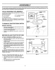
ASSEMBLY HOW TO SET UP YOUR TRACTOR PREPARE I _ BATTERY I' INSTALL SEAT (See Fig. 4) Adjust seat before tightening adjustment knob_ (See FJg._3) ii iij iiiiiii i ii ° IIII Remove cardboard packing on seat pan. CAUTION: Wear eye and face shield. ° Place seat on seat pan and assemble shoulder boll Wash hands or clothing immediately if • Assemble adjustment knob and fiat washer loosely. Do not tighten. Tighten shoulder bolt securely. ° Do not smoke.
INSTALL MOWER AND DRIVE BELT (See Figs. 5 and 8) ° • Be sure tractor ison level surfacel Engage parking bra!_o o o ° o = ° o Cut and remove tie down wire between anti-sway bar and R.Hogauge wheel bracket.,Swing anti-sway barto left side of mower deck,. ' Place the suspension arms on deck pins.
BLY CHECK DECK LEVELNESS For best cuttingresults, mower housing shouldbe properly_. leveled_ See "TO LEVEL MOWER HOUSING" in the_, Service and Adjustments section of t his manual CHECK BELTS FOR PROPER POSITION HEX BOLT OF ALL (NEGATIVE) BLACK CABLE See the figures that are shown for replacing motion, mower drive, and mower blade drive belts in the Service and Adjustments section of this manual, Verify that the belts are routed correcUy. LOCK WASHER DRAIN TUBE FIG. 6 INSTALL BATrERY (See Figs.
OPERATI KNOW YOUR TRACTOR READ THIS OWNER'S MANUAL AND SAFETY RULES BEFORE OPERATING YOUR TRACTOR.
The operation of any tractor can result in foreign objects thrown into the eyes, which can result in severe eye damage, Always wear safety glasses or eye shields while operating your tractor or pe_orminganyadjustme_s or repaizs. We recommend a wide vision safety mask for over the spectacles or standard safety glasses, HOW TO USE YOUR TRACTOR TO SET PARKING CAUTION: Always stop tractor completely, as described above, before leaving the operator's position; to empty grass catcher, etc. BRAKE (See Fig.
OPERATION TO ADJUST GAUGE WHEELS o ° Adjust mower to desired cutting height, Lower mower with lift control Removeo_ear retainer spring and clevis pin which s_cure each gauge wheel, • Lower gauge wheels to ground° Raise gauge wheels slightly to align holes in bracket and gauge wheel bar, and insert clevis pins, Gauge wheels should be slightly off the ground° ° TO OPERATE (See Fig. 10) I Replace retainer springs into clevis pins.
ADD GASOLINE MOWING TIPS • Fi!! fuel tank. Use fresh, clean, regular unleaded gasoline. (Use of leaded gasolin._ willi_q.cr_a,_ca_o_'-; and lead oxide deposits and reduce v_a'lvelire)_ .....
CUSTOP,!I MAINTENANCE SCHEDULE /'__o _"_o__/ AS YOU COMPLETE _'__Z_.?,-_Z_og-_" REGULAR SERV!C_E_.......................................... __'_SERVICE CheckB keOporation " ........... C CheckTire Pressure i 6_ Checkfor LooseFasteners i_ 0 LubricationChart .Check.Batte.rY Level/Recharge ................ " ' Clean Batteryand Terminals R CheckTransaxleCooling " ! : : : 6#4 6#4 6#4 __ ................................... 6##' _ 6## 6#_'_ $_s . I . = = , 6#4 • . z ...............
TRACTOR TO SHARPEN Always observe safety rules when performing any mainte-.. nance. Care should be taken to keep the blade balanced, An unbaPancedbladewillcause excessive vibration and eventual damage to mower' and engine_ BRAKE OPERATION • If tractor requires more than six (6) feet stopping distance at high speed in highest gear, then brake must be adjusted. (See 'q'O ADJUST BRAKE" in the Service and Adjustmerits section of this manual). • TIRES ° BLADE (See Fig.
PO CUSTOMER o Disconnect BLACK battery cable first then RED battery cable and remove battery from tractor° • Wash battery with solution1 of fou_,_tablespoons;,0t_ bakingsodatoonegallon ofwater, Becareful nottoget the soda solution into the cells. • Rinse the battery with plain water and dry° ° Clean terminals and battery cable endswith wire brush until bright. SAE VISCOSITY I =F • Coat terminals with grease or petroleum jelly.
RESPONSIBILITIES CLEAN AIR SCREEN (See Fig. 20) Air screen must be kept free of di_ and chaff to prevent:_ engine damage from overheating° ,Clean with,_wire brU_h'_ or compressed air to remove dirt and stubborn dried gum fibers. ENGINE COOLING FINS (See Fig. 20) Remove any dust, dirt or oil from engine cooling fins to prevent engine damage from overheating° Engine blower housing must be removed.
SERVICE AND ADJUSTMENTS CAUTION: BEFORE PERFORMING ANY SERVICE OR ADJUSTMENTS: o Depress clutch/brake pedal fully and set parking brake. = Place gearshift-lever in_neutral (N),position, • Place attachment clutch in "DISENGAGED" position. ° Turn ignition key"OFF" and remove key. ° Make sure the blades and all moving parts have completely stopped. o Disconnect spark plug wire from sparkplug and place wire where it cannot come in contact with plug. .........
AND ADJUSTMENTS FRONT-TO-BACK ADJUSTMENT (See Figs. 25 and 26) IMPORTANT: DECK MUSTBE LEVELSIDE-TO-SIDE. 1F THE FOLLOWING FRONT-TO-B,_CK ADJ._IS.TMENT IS_, NECESSARY, BE SURE TO ADJUST BOTH'_'R'_R'FEINKS* EQUALLY SO MOWER WILL STAY LEVEL SIDE*TO-SIDE. To obtain the best cutting results, the mower housing should be adjusted so the front isapproximately 1/8" to 1/2" lower than the rear' when the mower is in its highest position° Check adjustment on right side of tractor.
RV CE AND ADJUSTMENTS TO REPLACE (See Fig. 28) MOWER BLADE DRIVE BELT .... Park the tractor on level surface. Engage parking brake+ • Remove mowerdrive belt (See'70 REPLACE MOWER DRIVE BELT" in this section of this manual). • Remove mower (See "TO REMOVE MOWER" in this section of this manual). • Remove four screws from Roll+ mandrel cover and remove cover° Unhook spring from bolt on mower housing+ • Carefully roll belt off R.H.
rllll AND ADJUSTMENTS "Hill IllUlIII IIIIIIIIIII IIIIIIIIIIIIIII TO REPLACE (See Fig. 31) ......................... IIIIIJ,J,!!!,, ,!,!,,,,,!,,,,!,, TO ADJUST STEERING WHEEL ALIGNMENT MOTION DRIVE BELT Park the tractor on level surface. Engage parking brake.
SERVICE AND ADJUSTMENTS TO REMOVE WHEEL FOR REPAIRS FRONT WHEEL (See Fig. 34) o Block up axle securely° • Removeaxle cover, retainingring and washersto ailow wheel removal° ° o Repair tire and reassemble. Replace washers and snap retaining ring securely in axle groove. ° Replace axle cover° "POSITIVE" (+) "NEGATIVE" (-) HERS RETAINING AXLE COVER FIG, 35 TO REPLACE FIG. 34 REAR WHEEL - HEADLIGHT BULB - Raise hood. ° Pull bulb holder out of the hole in the backside of the grill.
illlUlllllllllllllll i IIIIILIIIIIIIIllLIIIII Illllll ,I X X ....................................... SERVICE AND ADJUSTMENTS TO ADJUST ATTACHMENT (See Fig. 36) LIFT SPRING • While holdingspring bushing with wrench, loosen jam nut. • Turn adjustment bolt clockwise to extend spring and reduce tift effort for heavier attachments. • Turn adjustment tachments. bolt counterclockwise ADJUSTMENT BOLT SPRING BUSHING for lighter atJAM ° Retighten jam nut against spring bushing.
ERVICE AND ADJUSTMENTS i, ENGINE ACCELERATION TO ADJUST THROTTLE (See Fig, 38 & 39) CONTROL = CABLE The throttle control has been preset at the factory and adjustment should not be necessary. Check adjustment as described below before loosening cable° If adjustment is necessary, proceed as follows: ° With engine not running, move throttlecontrol lever to fast 0 position. o Checkthat speed controllever isagainst stopscrew.
ENGINE Immediately prepare your tractor for storage at the end of the season or if the tractor will not be used for 30 days or more. FUEL SYSTEM IMPORTANT: IT IS IMPORTANT TO PREVENT GUM DEPOSITS FROM FORMING IN ESSENTIAL FUEL SYSTEMPARTS SUCH AS CARBURETOR, FUEL FILTER, FUEL HOSE, OR TANK DURING STORAGE. ALSO, EXPERIENCE INDICATES THAT ALCOHOL BLENDED FUELS (CALLED GASOHOL OR USING ETHANOL OR METHANOL) CAN ATTRACT MOISTURE WHICH LEADS TO SEPARATION AND FORMATION OF ACIDS DURING STORAGE.
TROUBLESHOOTING POINTS PROBLEM CAUSE CORRECTION Will not start I. 2_ 3, 4. 5. 6, 7 1_ 2. 3, 4, 5, 6 7 Outof fuel. Engine not "CHOKED" pmpedy Engine flooded. Bad spark plug Dirty air filter,, Dtrty fuet filter_ Water In fuel Filt fuel tank. See "TO START ENGINE" in Operation section, Walt severed minutes before attempting to start, Reptace spark plug. Clean/replace air fitter,. Replace fuel filter,, Drain fuel tank and carburetor, refill tank with fresh gasofine and replace fuel fffter.
POINTS i PROBLEM CAUSE ,ll,,ll,l,ll,,lll,,i,,_.ju,,i,,, i CORRECTION ±1 i _1 _r Engine continues to run when operator leaves seat with attachment clutch engaged l Faulty operator-safeiy presence control system Poor cut - uneven 1,, 2. 3, 4,, Wom, bent or loose blade Mower deck net level, Buildup of grass, leaves, and trash under mower. Bent blade mandrel 5. Clogged mower deck vent hotes from buildup of grass, leaves, and trash around mandrels.
18 HP 44" TRACTOR - MODEL NUMBER 917.255980 SCHEMATIC BATTERY RED FUSE 30 AMP, AMMETER WHITE ' IC Dl _____ ' -1---' i I@', 1 STARTER " J SOLENOID F _ t1 CLUTCH / BRAKE (PEDAL UP) l IGNITION "_ SWITCH B t_ RED ,, ! E_ (_, ELECTRIC CLUTCH | kJ'_"_ I I L ...... | ......... PTO (DISENGAGED) t_ AO =_ RED T ! ........ SEAT SWITCH (NOT OCCUPIED) BLACK ._D 86 I ,__, t 87 "I .... l-'- l__, 8LACK,, lw h I t 85 _ BLACK. 30 '[ 0..
REPAIR PARTS 18 HP 44" TRACTOR - - MODEL NUMBER 917.255980 DECALS 18 6 3 15 7 15 4 13 8\ 8 13 7 10 9 \ 11 KEY NO. PART NO. 'I 2 3 4 5 6 7 8 9 10 11 136794 138591 138042 138O43 138264 133644 138048 128538 128314 137537 4900J I2 KEY NO. DESCRIPTION 12 13 14 15 17 18 19 23 --- Decal, Operating Instruction Decal. Grill GT 6000 USA BIack Decal Hood, Craftsman, RH Decal Hood, Craftsman, LH Decal .
REPAIR PARTS 18 HP 44" TRACTOR- MODEL NUMBER 917.
REPAIR PARTS 18 HP 44" TRACTOR- MODEL NUMBER 917,255980 ELECTRICAL NO. NO.
REPAIR PARTS 18 HP 44" TRACTOR - MODEL NUMBER 917.
REPARR PARTS 18 HP 44" TRACTOR CHASSIS - MODEL NUMBER 917.255980 AND ENCLOSURES KEY NO. PART NO.
REPAIR PARTS 18 HP 44" TRACTOR - MODEL NUMBER 917.
REPAIR PARTS 18 HP 44" TRACTOR - MODEL NUMBER 917.255980 GROUND DRIVE KEY NO. PART NO.
REPAIR PARTS 18 HP 44" TRACTOR - MODEL NUMBER 917.
REPAIR PARTS 18 HP 44" TRACTOR STEERING - MODEL NUMBER 917.255980 ASSEMBLY KEY NO. PART NO.
REPAIR PARTS 18 HP 44" TRACTOR - MODEL NUMBER 917.255980 ENGINE 20 34 30 36 6 i 1 i 1 j14 39 i t t i 1 i I l i i 19 i 17 11 43 42 41 29 _.
REPAnR PARTS 18 HP 44" TRACTOR - MODEL NUMBER 917.255980 ENGINE KEY NO. 1 2 PART NO. 137303 139214 3 4 5 6 8 9 10 11 12 13 14 15 16 17 t8 19 13240300 13280328 13200300 138129 12!361X 138559 105432X 137140 136907 138486 138487 141069 109227X 106082X 123549X 13290300 20 21 22 138673 17720410 138672 DESCRIPTION Engine Kohler 18 IC Mag Vert Muffler Asm Kohler VGT (Inc. Key No.
REPAIR PARTS 18 HP 44" TRACTOR - - MODEL NUMBER 917.255980 SEAT ASSEMBLY KEY NO. 1 2 3 4 5 6 7 8 9 10 11 12 PART NO. 127438X 126656X 105511X 127018X 140407 73680600 124181X 17490508 19131614 131451 121251X ! 21246X KEY NO. DESCRIPTION Seat Bracket, Pivot Seat Strap, Fender Bolt, Shoulder 5/16-18 X .62 Clip, Push tn Nut, Crownlock 3/8-16 Unc Spring, Seat Cprsn Screw, Thdrol 5t16-18 X 1/2 Washer 13/32 X 1 X 14 Ga_ Pan, Seat Strip, Foam Bracket, Mounting Switch 13 14 15 16 17 18 19 20 21 22 PART NO.
REPAIR PARTS 18 HP 44" TRACTOR - MODEL NUMBER 917.255980 LIFT ASSEMBLY 35 17 34 33 31 _3:_ /,/3_ 8 7 \_ 9 10N, _ 29 2 12 ..___ 23 12 24 \ 25 26 12 16 22 '12 13 2O 19 KEY NO. PART NO. 1 2 3 4 5 6 7 8 9 10 1t 12 13 14 15 16 17 18 19 20 21 22 23 121006X 137295 121002X 12000022 19292016 74780624 125631X 122365X 122364)( 2876H 138020 3146R 138023 19131611 7,3800600 674A2.47 73350600 5329J 19131316 5328J 74760616 127218 4939M KEY NO.
REPAIR PARTS 18 HP 44" TRACTOR - MODEL NUMBER 917.255980 44" MOWER DECK 55 45 48 48 63 47 3O 60 59 6 _,.
REPARR PARTS 18 HP 44" TRACTOR - MODEL NUMBER 917.255980 44" MOWER DECK KEY NO. PART NO. 1 2 3 4 5 6 7 8 9 10 11 12 13 140579 73800500 7211O506 7631J 138457 4939M 130832 850857 10030600 129962 130652 129895 137553 14 15 t6 17 18 19 20 21 22 23 24 25 26 27 28 29 30 31 137152 110485X 136929 106735X 19111016 105304X 1237t3X 137607 110452X 109785X 136321 19111216 72110614 19131316 132823 73800600 78158 137266 DESCRIPTION KEY NO. PART NO. Deck Asm.
REPAIR PARTS 18 HP 44" TRACTOR - MODEL NUMBER 917.
REPAIR PARTS 18 HP 44" TRACTOR - MODEL NUMBER 917.255980 TRANSAXLE KEY PART NO. NO.
REPAIR PARTS 18 HP 44" TRACTOR - MODEL NUMBER 917.
REPAIR PARTS 18 HP 44" TRACTOR - MODEL NUMBER 917,255980 KOHLER ENGINE - MODEL NUMBER MV18S, TYPE NUMBER 58556 AIR INTAKE KEY NO. PART NO. 1 2 ){-276-7 52 755 83 3 4 5 6 7 8 9 10 52 096 35 52 123 21 231032 52 082 04 45 083 01 45 083 02 237423 X-67-98 1t t2 13 14 15 52 201 06 277093 52 05439 X-25-79 X-50°37 16 X-50-57 t7 X-22-9 18 25 041 06 BAFFLES & SHROUD DESCRIPTION KEY NO.
REPAIR PARTS 18 HP 44" TRACTOR - MODEL NUMBER 917,255980 KOHLER ENGINE - MODEL NUMBER MV18S, TYPE NUMBER 58556 CRANKCASE I 4 19-- 13 3 ! 5 CARBURETOR I 12 10 50 tl / 15
RE!PAIR PARTS 18 HP 44" TRACTOR - MODEL NUMBER 917,255980 KOHLER ENGINE - MODEL NUMBER MV18S, TYPE NUMBER 58556 CRANKCASE KEY NO. PART NO.
REPAIR PARTS 18 HP 44" TRACTOR KOHLER ENGINE - MODEL NUMBER CRANKSHAFT I - MODEL NUMBER MV18S, TYPE NUMBER ] 5 --6 7 J EXHAUST I 4_ 3 2 1 58556 CYLINDER HEAD I DIPSTICK ! O_4 ELECTRIC STARTER 917.
REPABR PARTS 18 HP 44" TRACTOR KOHLER ENGINE - MODEL NUMBER - MODEL MV18S, TYPE NUMBER CRANKSHAFT KEY NO. 1 2 52 52 52 52 DESCRIPTION 0!4 468 468 468 Crankshaft Washer, Thrust _119/.122 (A,R.) Washer, Thrust .128/.131 Washer, Thrust o137L!40 (AoRo) DIPSTICK KEY NO. PART NO. 1 52038 14 2 3 4 5 6 7 X-25-44 52 032 14 41 15301 52 126 11 52 t2320 47 13901 DESCRIPTION PART NO. t 2 3 4 52 041 20 52 015 08 22O534 41 08602 KEY NO. PART NO.
REPAIR PARTS 18 HP 44" TRACTOR KOHLER ENGINE - MODEL NUMBER - MODEL NUMBER MV18S, TYPE NUMBER 917,255980 58556 FUEL PUMP ] 1 3 26 2s/'_ 27 24 2 10 iGN,T,ON I ,FLYWHEEL II IIIIIIL L ......
REPAUR PARTS 18 HP 44" TRACTOR -MODEL NUMBER KOHLER ENGINE - MODEL NUMBER MV18S, TYPE NUMBER FLYWHEEL KEY NO. PART NO. 1 2 25 162 01 25 086 21 3 4 5 6 7 8 25 112 04 25 157 01 25 086 24 52 468 15 X-286-17 52 025 36 PART NO.
REPAIR PARTS 18 HP 44" TRACTOR - MODEL NUMBER 917.255980 KOHLER ENGINE - MODEL NUMBER MV18S, TYPE NUMBER 58556 , ,,,, OIL FILTER OIL PAN i' 1_ I ,,,,,,,,, ,,, ,,,,,,,,,,, ,,,,,,,,,,,,,,,,,,, i,i, ,11 _---2 I , _L-_7 ! l-o s 2 LSW,TC_,,[ ,,,_To ,,,,No Ro0,,,,,, I........................................ 0!, 1 / 2 OIL PUMP I 4 1_'_.,.
REPAIR PARTS 18 HP 44" TRACTOR KOHLER ENGINE- - MODEL PART NO. 1 X-67_64 2 3 4 5 52 050 03 52 19908 X-702-15 52 086 12 6 7 52032 10 X-75-10 LOW OIL PRESSURE SWITCH DESCRIPTION KEY NO. Screw, Hex Washer Head #10-32 x 7/16 (2) Filter, Oil Pickup Oil Pan (Includes Key Number 4) Plug, Cup 5/16 Screw, Hex Washer Head 5/16-18 x t-1/4 (9) Seal, Oil, Rear Plug, Square Head 3/8 N_P_T,F,(2) 1 PART NO.
SERVICE NOTES 58
SUGGESTED GUIDE FOR SiGHTiNG SLOPES FOR SAFE OPERATION ONLY RIDE UP AND DOWN HILL, NOT ACROSS HILL SIGHTING GUIDE SIGHT AND HOLD THIS LEVEL WITH SKY LINE OR TREE. O1 (O 15 ° MAX. i iiiillliiIllllll' ' ......................................... _t /_ t!| _ _| _ Operate your Tractor up and down the face of slopes (not ! greater than 15 ), never across the face. Make turns gradu.- i ally to prevent tipping or loss of control.
CRIIFTSMIIN® OWNER'S MANUAL 18.0 HP TWIN CYLINDER ELECTRIC START 44" MOWER 6 SPEED TRANSAXLE GARDEN TRACTOR Each tractor has its own model number° Each engine has its own model number° MODEL NO. 917.255980 The model number' for your' tractor will be found on the model plate located under the Seat The model number for your engine will be found on the blower' housing of the engine_ All parts listed herein may be ordered from any Sears, Roebuck and Co.