
Owner`s manual


.................... i i i i illlllllll,i
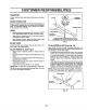
AIR FILTER (See Fig. 13)
Your engine will not run properrIyusing a dirty air filter_
Clean the foam pre-cleaner after every 25 hours of opera-
tion or every season_ Service paper cartridge every 100
hours of operation or every season, whichever' occurs first.
Service air cleaner more often under dusty conditions.
• Remove knob(s) and cover'.
TO SERVICE PRE-CLEANER
• Slide foam pre-cleaner off cartridge_
• Wash it in liquid detergent and water.
° Squeeze it dry in a clean cloth.
° Saturate it in engine oil. Wrap it in clean, absorbent
cloth and squeeze to remove excess oil.
. If very dirty or damaged, replace pre-cleaner.
° Reinstall pre-cleaner over cartridge.
• Reinstall cover and secure with knob(s)_
TO SERVICE CARTRIDGE
, Remove cartridge nut.
• Carefu!ly remove cartridge to prevent debris from en-
terin_l carburetor. Clean base carefully to prevent
debris from entering carburetor.
• Clean cartridge bytapping gentlyon flat surface, Ifvery
dirty or damaged, replace cartridge.
° Reinstall cartridge, nut, precleaner, cover and secure
with knob(s)o
IMPORTANT: PETROLEUM SOLVENTS, SUCH AS
KEROSENE, ARE NOT TO BE USED TO CLEAN THE
CARTRIDGE° THEY MAY CAUSE DETERIORATION OF
THE CARTRIDGE. DO NOT OIL CARTRIDGE, DO NOT
USE PRESSURIZED AIR TO CLEAN OR DRY
CARTRIDGE.
COVER KNOB -'-_''''''_
CUSTOMER RESPONSiBIL
CARTRIDGE NUT
PAPER
CARTRIDGE
CLEAN AIR SCREEN (See Fig. 14)
Air screen must be kept free of dirt and chaff to prevent
engine damage from overheating, Clean with a wire brush
or compressed air to remove dirt and stubborn dried gum
fibers,
ENGINE COOLING FINS (See Fig. 14)
Remove any dust, dirt or oil from engine cooling fins to
prevent engine damage from overheating.
. Remove screws from blower housing and lift housing
and dipsticktube assembly off engine.
• Cover oil fill openingto prevent entry of dirt.
• Use compressedair or stiff bristle brush to thoroughly
clean engine coolingfins,,
• To reassemble, reverse above procedure.
SCREWS
BLOWER HOUSING
SCREWS
DIPSTICK AIR SCREEN ENGINE
TUBE !COOLING FINS
ASSEMBLY
SPARK
PLUG
FIG. 14
FIG. 13
18