SEARS CRRFr,SM MODEL NUMBER 917.256890 OWNER'SMANUAL o Assembly Operation Customer Responsibilities Service and Adjustments Repair Parts CAUTION: Read and follow FOR CONSUMER i"rl all safety ASSISTANCE rules and instructions before operating HOT LINE, CALL THIS TOLL FREE NUMBER: ............................................ this equipment.
SAFETY Practices RULES for Ride-On Safe Operation A Mowers IMPORTANT: THIS CUTTING MACHINE IS CAPABLE OF AMPUTATING HANDS AND FEET AND THROWING OBJECTS. FAILURE TO OBSERVE THE FOLLOWING SAFETY INSTRUCTIONS COULD RESULT IN SERIOUS INJURY OR DEATH. II1. CHILDREN I, GENERAL • Read, understand, and follow alt instructions in the manual and on the machine before starting. Only allow responsible adults, who are familiar with the instructions, to operate the machine.
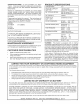
PRODUCT CONGRATULATIONS on your purchase of a Sears Tractor. It has been designed, engineered'and manufactured to give you the best possible dependability and performance. SPECIFICATIONS HORSEPOWER: 15.5 GASOLINE CAPACITY AND TY_PE: t .25 GALLONS UNLEADED REGULAR OIL TYPE (API-SF/SG): SAE 30 (above 32'_F) SAE 5W-30 (below 32°F) OtL CAPACITY: 3 PINTS SPARK PLUG: (GAP: .030") CHAMPION RJt9LM VALVE CLEARANCE: INTAKE: .005" - .007" EXHAUST: .
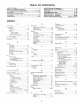
TABLE OF CONTENTS SAFETY RULES ............................................................ 2 PRODUCT SPECIFICATIONS ...................................... 3 CUSTOMER RESPONSIBILITIES ..................... 3, 15-18 WARRANTY .................................................................. 3 TRACTOR ACCESSORIES .......................................... 5 ASSEMBLY ................................................................ 7-9 OPERATION ...........................................................
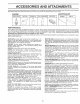
ACC RIES AND ATTACHMENTS These accessories and attachments were available th rough most Sears retail outlets and service centers when the tractorwas Most Sears stores can order these items for you when you provide the model number of your tractor. MAINTENANCE ENGINE SPARK PLUG : purchased, GAS CAN ENGINE OIL FUEL STABtUZER AIR FILTER BLADES BELTS PERFORMANCE Sears offers a wide variety of attachments that fit your tractor. you.
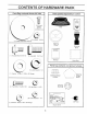
CONTENTS OF HARDWARE PACK . Parts / Bag contents / shown full size Parts packed separately . _ ..... in carton ".
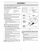
ASSEMBLY Your new tractor has been assembled at the factory with exception of those parts left unassembled for shipping purposes. To ensure safe and proper operation of your tractor all parts and hardware you assemble must be tightened securely. Use the correct tools as necessary to insure proper tightness. TOOLS REQUIRED FOR ASSEMBLY A socket wrench set will make assembty easier. Standard wrench sizes are listed.
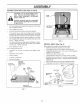
AS CONNECT BATTERY iVlBLY (See Figs. 2 and 3) CAUTRON: Do not short battery terminals. Before connecting battery, re- SEAT PAN bands, rings, etc. move metal bracelets, wristwatch Positive terminal must be connected first to prevent sparking from accidental grounding. ° , Remove cardboard packing from seat pan and lift seat pan to raised position. BOX DOOR C sen battery box door. Remove terminal protective caps and discard.
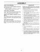
ASSEMBLY CHECK TIRE ,/CHECKLIST PRESSURE The tires on your tractor were overinflated at the factory' for shipping purposes. Correct tire pressure is important for best cutting performance. • Reduce tire pressure to PSi shown in "PRODUCT SPECIFICATIONS on page 3 of this manual. CHECK DECK LEVELNESS For best cutting results, mower housing should be properly leveled. See "TO LEVEL MOWER HOUSING" in the Service and Adjustments section of this manual.
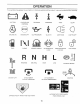
OPERATIO These symbols may appear on you r tractor or in literature supplied with the product. Learn and understand their meaning, BATTERY CAUTION OR WARNING REVERSE FORWARD FAST SLOW ENGINE ON ENGINE OFF OIL PRESSURE CLUTCH LIGHTS ON LIGHTS OFF FUEL CHOKE MOWER HEIGHT DIFFERENTIAL LOCK PARKING BRAKE LOCKED UNLOCKED REVERSE MOWER _IFT NEUTRAL &TTACHMENT CLUTCH ENGAGED HIGH LOW PARKING BRAKE ATTACHMENT CLUTCH DISENGAGED HYDROSTATIC DANGER.
m OPERATION KNOWYOURTRACTOR READ THIS OWNER'S MANUAL AND SAFETY RULES BEFORE OPERATING YOUR TRACTOR Compare the itlustrat ons w th your tractor to fami iarize yourself with the locations of various controls and adjustments. Save this manual for future reference, ATTACHMENT CLUTCH LEVER AMMETER IGNITION SWITCH LIGHT LIFT LEVER PLUNGER SWITCH THROTTLFJCHOKE ATTACHMENT LIFT LEVER CONTROL CLUTCH/BRAKE PEDAL © _,_ FREEWHEEL CONTROL HEIGHT ADJUSTMENT POSITIONS MOWER DECK PARKING BRAKE APPROX.
OPERATION ......... . .... = The operation of any tractor can result in foreign objects thrown into the eyes, which can result in severe eye damage. Always wear safety glasses or eye shields while operatingyourtractororperforming any adjustments or repairs. We recommend awide vision safety mask over the spectacles or standard safety glasses.
OPERATION I without either the entire gr sa s catcher, on mowers so equipped, or the discharge guard in place. l ATTACHMENT CLUTCH LEVER "DISENGAGED" POSITION -"ENGAGED" POSITION / ATTACHMENT FIG, 8 HIGH POSITRON BEFORE STARTING CHECK POSiTiON , • DISCHARGE GUARD • FiG. 7 TO OPERATE _ ON HILLS - ! Choose the slowest speed before starting up or down hills. • • Avoid stc ;)ping or changing speed on hills. If sIowing s necessary, move throttle control lever to slower position.
OPERATION InsertKeyintoignitionandturn Keyclockwiseto"START" oosition and t'eleaSe key as soon as engine starts, Do qo_ run starter continuously for more than fifteen seconus oer minute, If the engine does not start after severn attempts, move throttle control to fast (,_} oosltlon, wait a few minutes and try again, If engine still does not start, move the throttle control back to the choke (IXI) position and retry.
CUSTOMER MAINTENANCE ESPO SCHEDULE LITIES , FILL IN DATES AS YOU COMPLETE REGULAR SERVICE T SERVICE DATES Check Brake Operation Check Tire Pressure tf i/ Chec k for Loose Fasteners i_R Sharpen/Replace Mower ! I/7 t_ LubricationOhart T Check Battery : 0 Clean Battery and Terminals R Check Transaxfe Adjust Blade Belt(s) Tension Adjust Motion Drive Belt(s) Tension Check Engine Oil Level t/ V', I/ Blades _ Change .....
CUSTOMER RESPC IBILITIES TRACTOR Always deservesafetyruleswhen performingany maintenance. BLADE MANDREL ASSEMBLY BRAKE OPERATION If tractor requwes more than six (6) feet stopping distance at h_ghspeed in highest gear, then brake must be adjusted. f See "TO ADJUST BRAKE" in the Service and Adjustmen_s section of this manual). TRAILING EDGE FLAT WASHER_ TIRES o o Maintain proper air pressure in al_ tires (See "PRODUCT SPECIFICATIONS" on page 3 of this manual). HEX BOLT (GRADE 8)* _.
CUSTO RESPONSIBILITIES BATTERY SAE VISCOSITY GRADES Your tractor has a battery charging system which is sufficient for normal use. However periodic charging of the battery with an automotive charger will extend its life. o 30 ° Keep battery and terminals clean. -30" - Keep battery bolts tight, • Keep small vent holes open. • Recharge at 6-10 amperes for 1 hour. -20 ° TEMPERATURE -100 RANGE 32o 40" 0_ ANT{CIPATED 60 ° 80 t0' 20 BEFORE t00 30_ NEXT OIL 40 ° SHANGE FIG.
CUSTOMER AiR FILTER RESPONSi (See Fig, !4) CLEAN Your engine will not run properly using a dirty air filter. CIean the foam pre-c]eaner after every 25 hours of operation or every season, Service paper cartridge every 100 _ours of operation or every season, whichever occurs first. ENGINE o Remove knob(s) and cover. TQ SERVICE PRE-CLEANER (See Fig, 15) COOLING FINS (See Fig.
CUSTOMER ESPONSIBILITIES MUFFLER Inspect and replace corroded muffler and spark arrester (if equipped) as it could create a fire hazard and/or damage. SPARK CLAMP_ / /CLAMP PLUGS Replace spark plugs at the beginning of each mowing season or after every 100 hours of operation; whichever occurs first. Spark plug type and gap setting are shown _n "PRODUCT SPECIFICATIONS" on page 3 of this manual. IN-LINE / FUEL FILTER FUEL FILTER (See Fig. 16) FIG.
SERVICE AND ADJUSTMENTS o Depress clutch/brake pedal fully and set parking brake, CAUTION: BEFORE PERFORMING ANY SERVICE OR ADJUSTMENTS: o Place motion control lever in neutral (N) position. * Place attachment ciutch in "DISENGAGED" position. Turn ignition key "OFF" and remove key. o Make sure the blades and all moving parts have completely stopped. Disconnect spark plug wire from spark plug and place wire where it cannot come in contact with plug. TRACTOR TO REMOVE CLUTCH LEVER MOWER (See Fig.
SERVICE TO LEVEL MOWER AND ADJUSTMENTS HOUSING FRONT-TO-BACK ADJUSTMENT (See Figs, 20 and 21) IMPORTANT: DECK MUST BE LEVEL SIDE-TO-SIDE. tF THE FOLLOWING FRONT-TO-BACK ADJUSTMENT IS NECESSARY, BE SURE TO ADJUST BOTH FRONT LINKS EQUALLY SO MOWER WILL STAY LEVEL SiDE-TOSIDE. Adjust the mower while tractor is parked on level ground or driveway, Make sure tires are properly inflated (See "PRODUCT SPECIFICATIONS" on page 3 of this manual).
SERVICE TO REPLACE (See Fig. 22) MOWER BLADE AND AD, USTMENTS DRIVE BELT WITH PARKING BRAKE "ENGAGED" _--'_-'_- NUT "A" The mower blade drive belt may be replaced without tools. Park the tractor on Eevelsurface. Engage parking brake. BELT REMOVAL - Remove mower from tractor (See "TO REMOVE MOWER" in this section of this manual). o Work belt off both mandrel pulleys and idler pulleys, o Pull belt away from mower. BELT INSTALLATION - Install new belt in reverse order of removal.
RVIC TO ADJUST MOTION CONTROL AND ADJUSTMENTS LEVER (See TO ADJUST Fig. 25) If for any reason the motion control lever will not hold its eosition while at a selected speed, it may be adjusted at the friction pack located on the right side of transmission. Park tractor on level surface..Stop tractor by turning ignition key to "OFF" position, and engage parking brake. • Adjust motion control lever by tightening adjustment 10cknut one half (1/2) turn.
SERVICE TO START ENGINE See Fig. 27) N_______ WtTH A WEAK AND ADJUSTMENTS BATTERY TO REPLACE CAU TlO Lea d.aci ate explosivegases, Keep sparks, flame and smoking materials away from bat reties. Always wear eye protection iMPORTANT: YOUR TRACTOR VOLT NEGATIVE GROUNDED VEHICLE MUST ALSO BE Raise hood. - Pull bulb holder out of the hole in the backside of the grill. • Replace bulb in holder andpush bulb holder securely back into the hole in the backside of the grill Close hood.
SERVICE AND ADJUSTMENTS ENGINE FINAL SETTING - TO ADJUST THROTTLE (See Fig. 29) CONTROL CABLE The throttle control has been preset at the factory and adjustment should not be necessary. Check adjustment as aescribed below before loosening cable, tf adjustment is necessary, proceed as follows: • = Start engine and allow to warm for five minutes. Make final adjustments with engine running and shift/motion control lever in neutral (N) position. - Move throttle control lever to slow (,_) position.
STORAGE ENGINE mmediately prepare your tractor for storage at the end of me season or if the tractor will not be used for 30 days or more A c2dT,o" - iroc i _J&A ga_ inside a building where fumes may reach an open flame or spark. Allow the engine to cool _lnany enclosure. . FUEL SYSTEM IMPORTANT: IT S IMPORTANT TO PREVENT GUM DEPOS TS FROM FORMING IN ESSENTIAL FUEL SYSTEM PARTS SUCH AS CARBURETOR FUEL FILTER. FUEL HOSE, OR TANK DURING STORAGE.
m TRO PROBLEM Will not start CAUSE Engine Engine start willnot turn over clicks but will not Loss of power NTS CORRECTION 1. Out of fuel. 2. 3. 4. 5. 6. 7. Engine not "CHOKED" Engine flooded. Bad spark plug. Dirty air filter. Dirty fuel fitter. Waterin fuel 8. 9. Loose or damaged wiring. Carburetor outof adiustment. 10, Hard to start LESHOOTI 1. 2. 3. 4. 5. 6. 7. properly. 8, 9, f0, Engine valves out of adjustment. FIII fuel tank. See "TO START ENGINE" in Operation section.
TROUBLESHOOTING CAUSE PROBLEM Engine continues to run when operator leaves seat w_th attachment clutch POINTS CORRECTION Check wiring, switches and connecbons. If not corrected, contact an authorized service center/ department, 1 Fauity operator-safety P"esence control system. 1. 2. Worn bent or loose blade Mower deck not leveI. 1 2 Replace blade Tighten blade bolt. Le le] mower decK, 3. 4. Buildub of grass, _eaves. and trash under mower. Bent blade mandrel.
TRACTOR - = MODEL NUMBER 917.256890 SCHEMATIC BLACK RED l BATTERY RED FUSE 30 AMP STARTER AMMETER :BLACK : T t--O.. I O i (PEDAL UP) LGNITION ' ' 1 SEAT SWITCH (NOT OCCUPIED) SWITCH t ....
REPAIR PARTS TRACTOR -= MODEL NUMBER 917.
REPAIR PARTS TRACTOR = - MODEL NUMBER 917.256890 ELECTRICAL KEY NO. PART NO.
REPAIR PARTS TRACTOR CHASSIS - .- MODEL NUMBER 917.
REPAIR PARTS TRACTOR CHASSIS - - MODEL NUMBER 917.256890 AND ENCLOSURES KEY NO. PART NO.
REPAIR PARTS TRACTOR - - MODEL NUMBER 917.
REPAIR PARTS TRACTOR - - MODEL NUMBER 9! 7.256890 DRIVE KEY NO. 1 2 3 8 lO 15 16 18 19 21 22 24 25 26 27 28 29 3o 31 32 34 35 36 37 38 39 40 41 42 44 45 46 47 48 49 50 51 52 53 55 56 57 59 PART NO.
REPAIR PARTS TRACTOR STEERING - - MODEL NUMBER 917.256890 ASSEMBLY / . / • 62 _-_36 46_ 47 14 | 13 f? j j17 8 27.
REPAIR PARTS TRACTOR STEERING = - MODEL NUMBER 917.256890 ASSEMBLY KEY NO. 1 2 3 4 5 6 7 8 9 10 11 12 13 14 15 16 17 18 19 20 21 22 23 24 25 26 27 28 29 30 32 36 37 38 39 40 41 42 43 46 47 62 PART NO.
REPAIR PARTS TRACTOR - - MODEL,2NUMSER 9!7.256890 SEAT ASSEMBLY _.j 8 .--9 21 z "25 & \ \ \ 23 "5 KEY NO. PART NO.
REPAIR PARTS TRACTOR - - MODEL NUMBER 917.256890 DECALS 9 6 t7 14 3 7 21 7 5 / 4 8 14 11 16 \ \ \ 22 \ 13 10 15 20 KEY NO. PART NO. 1 2 3 4 5 6 7 8 9 10 11 12 13 138955 273270 150676 15O677 15068O 133644 142235 15O685 128314 149516 137537 4900J 146046 WHEELS DESCRIPTION 14 15 I6 I7 18 t9 20 2t 22 ------ Decal Instruction Operat Eng Decal, B&S 15.
REPAIR PARTS TRACTOR - - MODEL NUMB ER 917.
REPAIR PARTS TRACTOR - - MODEL NUMBER 917.256890 ENGINE KEY NO. 1 2 3 PART NO. 132759 17720410 150458 4 13 t4 15 16 23 29 31 32 33 35 37 38 137352 272293 13280324 13200300 STD551237 150554 137180 109202X 123549X 123487X 17490512 137040 ...... 40 44 46 62 72 78 81 124028X 17490412 19091418 STD551131 71070512 17490620 128861 NOTE: DESCRiPTiON Control Throt Rh BIk Pd115 10 Screw Hex Thd Cut 1/4-20x5/8 T Engine B&S 15/15.5 DlC & GD DC 1 Model No.
REPAIR PARTS TRACTOR - - MODEL NUMBER 917.256890 LIFT 7 5 13 _. 3 %.
REPAIR PARTS TRACTOR = - MODEL NUMBER 917.256890 LIFT KEY NO, PART NO, 1 2 3 4 5 6 7 8 10 11 12 13 15 16 17 18 19 20 31 32 136973 122507X 105767X 12000002 19211621 120183X 12563IX 122365X 122512X 139865 139866 STD624008 127218 73350800 130171 73800800 139868 STD624008 140302 73540600 NOTE: DESCRIPTION Rod Asm. Lever Shaft Asm. Lift Pin Groove E Ring #5133-62 Washer 21/32 x 1 x21 Ga. Bearing Nylong Grip Handle _luted Button Plunger Read Spring Cprsn Link Asm Lift L.H. Link Asm Lift R.H.
REPAIR PARTS TRACTOR - - MODEL NUMBER 917.256890 MOWER .
REPAIR PARTS TRACTOR - - MODEL NUMBER 917.256890 MOWER KEY NO, PART NO.
REPAIR PARTS TRACTOR HYDRO GEAR TRANSAXLE - =MODEL - MODEL NUMBER NUMBER 917.256890 310-0500 !35 58 37 34 139 18 `% 59 J 26 23 \ 3O 17 14 99 7 6 4. / / 5 / 2 114 .
REPAIR PARTS TRACTOR HYDRO GEAR TRANSAXLE - - MODEL . MODEL NUMBER KEY PART NO. NO, DESCRIPTION 1 2 3 a 5 6 7 8 9 13 14 15 17 18 19 23 24 25 26 27 28 29 30 34 35 36 37 38 39 Housing, Lower Assembly, Upper Housing Sea1, Lip Ring, Wire Retaining Ring, Retaining Bearing, Shaft Ball Bearing, Cradle Bearing, Thrust 30 x 52 x 13 Swashptate Variable Block, Cylinder Assembly Arm, Trunnion Sea, Lip Guide, Slot Shaft.
REPAIR PARTS TRACTOR BRIGGS & STRATTON ENGINE - - MODEL - MODEL NUMBER NUMBER 28N707, 917.256890 TYPE NUMBER 0t73-01 306 635 @ 337 REQUIRES SPECIAL TOOLS TO INSTALL. SEE REPAIR iNSTRUCTION MANUAL.
REPAIR PARTS TRACTOR BRIGGS 127 - - MODEL NUMBER & STRATTON ENGINE o MODEL NUMBER 138 95 634 10698-/ 117 28N707, 917.256890 TYPE NUMBER 0173,01 634B
REPAIR PARTS TRACTOR BR1GGS & STRATTON ENGINE 3 523 -- MODEL NUMBER - MODEL 20 634A NUMBER 842 28N707, 524 868 917.256890 TYPE NUMBER 868A 0173-01 467 537 171 _524 138 _i 1 ©) 137 977 CARBURETOR GASKET 668 304 78 468 305_ 346 37 1006 729 • . ....
REPAIR PARTS TRACTOR BRIGGS & STRATTON ENGINE - = MODEL - MODEL NUMBER NUMBER 28N707, 9!7=256890 TYPE NUMBER 0173o01 663 877 187 265 209 1019 [1058 LABEL OWNER'S KIT] j 240 601 MANUALI 783 801 J 1090 J \\ 311 j- 51
REPAIR PARTS TRACTOR BRIGGS & STRATTON KEY PART NO.
REPAIR PARTS TRACTOR BRIGGS & STRATTON KEY PART NO. NO.
SERVICE 54 NOTES
Z 0 I- ,< it rr' 111 I:L ! ! 0 I UJ 14. I ¢0 O: 0 u. t_ 111 0 ,.
® OWNER'S MANUAL MODEL NO, 917.256890 15.5 HP IC ELECTRIC START 42" MOWER HYDROSTATIC (AUTOMATIC) LAWN TRACTOR Each tractor has its own model number. its own model number. Each engine has The model number for your tractor will be found on the model plate located under the seat. The model number for your engine will be found on the blower housing of the engine.