® L U 917.
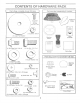
OOHT£HT$ ,,a OF H RE OK C \ \ (2} Sheet Meta Screws .t /_os (i) Locknut 3/8o24 (1) Large Flat Washer Video Cassette 'Wheel Boot (1) _shou_derBolt 5/16oi8 (_ j Hex Bu ...... .-o,,_x 1 M_.
ASSE Your new tractor has been assembled at the factory with exception of those parts Ueffunassembted for shipping purposes. To ensure safe and proper operation of your tractor all parts and hardware you assemble must be tightened securely° Use the correct too_s as necessary to insure proper tightness. TOOLS REQUIRED FOR ASSEMBLY A socket wrench set will make assembly easier. Standard wrench sizes are listed.
;E HOW TO SET UP YOUR TRACTOR CONNECT BAKERY (See Figs. 2 and 3) SEAT PAN CAUTION: Do not short battery termio hats by allowing a wrench or any other obieet to contact both terminals at the same time,, Before conneetin 9 battery, remove meta_ bracelets, wristwatch bands, rings, etco BATTERY BOX DOOR Positive terminam must be connected first to prevent sparking from acciden° tat grounding° o Remove cardboard packing from seat pan and tilt seat pan to raised position.
LY INSTALL t\,IULCHER PLATE NOOK POINTS (See Figs, 5 and 6) - WELD NUT FROM THE TOP Install two Jatch hooks to mulcher pBate using screw, washer, lock washer, and weid nut as shown. NOTE: Pre-assemble weld nut to latch hook by inserting weld nut from the top with hook pointing down° - Tighten hardware securelyo ® Raise and hold deflector shield in upright position. • Place front of mulcher plate over front of mower deck opening and slide into place, as shown.
...... ASSE LY ,/CHECKLIST CHECK TmRE PRESSURE BEFORE YOU OPERATE AND ENJOY YOUR NEW TRACTOR, WE WISH TO ASSURE THAT YOU RECEIVE THE BESTPERFORMANCEAND SATISFACTION FROM THIS QUALITY PRODUCT. The tires on your tractor were ov_rinflat_tbry for shipping purposes. Correct tire pressure is impQrtar}t for best cutting performance. ..... Reduce tire pressure to PSi shown in "PROE_UCT SPECIFICATIONS" on page 3 of this manual.
OPE 0 These symbots may appear on your tractor or in literature supplied with the product. Learn and understand their meaning.
}
E vision safety mask over the spectacles HOW TO USE YOUR TRACTOR TO SET PARKING BRAKE or standard safety, gmasseso NOTE: Under certain conditions when tractor is standing idle with the engine running, hot engine exhaust gases may cause "browning '_of grass. To eliminate this possibility, always stop engine when stopping tractor on grass areas.
TO OPERATE MOWER(See TO OPERATE Fig, 9) ON H_LLS Your tractor is equipped with an operator presence sensing switch. Any attempt by the operator tp leave the seat with the engine running and the attachment clutch engaged will shut off the engine. o Select desired height of cut. o Sta_t mower blades by engaging a_achment control Choose" Avoid stopping or changing speed on hilts. TO STOP MOWER BLADES o disengage attachment clutch control.
CUSTOMER ES ESPONSIB TRACTOR TO SHARPEN Always observe safety rules when performing any mainte° Care shouk_ be taken to keep the blade balanced. An unbalanced blade will cause excessive vibration and eventuat damage to mower and engine° nar_ceo BRAKE OPERATION TIRES Maintain proper air pressure in ali tires (See "PROD° UCT SPEC!FICATIONS" on page 3 of this manual). o Keep tires free of gasoline, oil, or insect controt chernicats which can harm rubber.
ES ES VoBELTS Check V-beJts for deterioration and wear after 100 hours of operation and replace if necessary. The belts are not adjustable. Replace belts if they begin to s_ip from wear° TRANSAXLE OiL F|LL CAP/DIPSTICK OOOUNG Keep transaxte free from build-up of dirt and chaff which can restrict cooling. OiL DRAIN PLUG ENGINE FiG.
PO CUSTOME CLEAN A_R SCREEN (See Fig, 16} IN-LiNE Air screen must be kept free of dirt and chaff to prevent engine damage from overheating. Clean with a wire brush or compressed air to remove dirt and stubborn dried gum fibers° ENGINE COOMNG Remove any dust, dirt. or oi! from engine coo!ing fins to prevent engine damage from overheating. Remove screws from blower housing and lift housing and dipstick tube assembly off engine.
EFIViCE A CAUTION: ® * * * , -= TO REMOVE ADJ ENTS gEFORE PERFORMING ANY SERVICE OR ADJUSTMENTS: Depress clutc_rbrake pedaJ fully and set parking brake, Place gearshift _ever in neutra| (N) position, PWaceattachment clutch in "DISENGAGED" position, Turn ignition key "OFF" and remove key= Make sure the blades and aU moving parts have completely stopped, Disconnect spark plug wire from spark piug and piace wire where it cannot come _n contact with plug° MOWER (See Fig.
SERVICE AN TO LEVEL MOWER A HOUSING FRONT-TO-BACK Adiust the mower while tractor is parked on level ground or Make sure tires are property inflated (See "PRODUCT SPECIFICATIONS" on page 3 of this manuat). tf tires are over or underinfiated, you will not properly adjust your mower. At the midpoint of both sides of mower, measure height from bottom edge of mower to ground. Distance "A" on both sides of mower should be the same or within 1/4" of each other.
ERVICE A TO REPLACE (See Fig.23) MOWER BLADE DRIVE ADJ BELT E W_TN PARKING BRAKE °'ENGAGED `° The mower b_ade drive belt may be replaced without tools. Park the tractor on levemsun'ace. Engage parking brake° BELT REMOVAL o * Remove mower from tractor (See "TO REMOVE MOWER" in this section of this manual). * Work belt off both mandrel pulleys and idler pulleyso * Pull belt away from mower. NUT °°A" BELT INSTALLATION * Install new be_t in reverse order of removal.
TO ADJUST STEERING WHEEL ALIGNMENT _fsteering whee_ crossbars are not horizontal (left to right} when wheels are positioned straight fosoe_a_d_ remove steering wheel and reassemble per instructions in the Assembly section of this manual. FRONT WHEEL TO START ENG_N_I: WITH A WEAK See Fig. 27} CAUT_O_S: L÷adoecid batteries genero ate exp_os_ve.{_aseso Keep sparks° flame ahd smoki_9 materials away from bat° teri®so Atways wear eye protection whe_ aro_d batteries.
SERVICE TO REPLACE HEADLIGHT ADJUSTM TO REMOVE BULB HOOD AND GRILL ASSEMBLY , Raise hood. (See Fig. 28) o Pul! bulb holder out of the hole in the backside of the grill , Raise hood. , Unsnap headlight wire connector. Replace bulb in holder and push bulb holder securely back into the hole in the backside of the grill Close hood. , Stand in front of tractor. Grasp hood at sides, tilt toward engine and lift off of tractor. ,, To replace, reverse above procedures.
SE ADJ FINAL SETTING o TO ADJUST THROSTLE CONTROL CABLE o Sta_ engine and allow to warm for five minutes. Make final adjustments with engine running and shiftJmotion contra_ Iever n neutra_ (N) pesitiono o Move throttle contrel lever to slow position. With finger, rotate and ho!d throttle lever against idle speed screw° Turn id;e speed screw to attain 1750 RPM.
STORAGE ENGINE mmmediately prepare your tractor for storage at the end of the season or if the tractor will not be used for 30 days or more. ab_iding _-each an open flame or spark.
PO PROBLEM CAOSE WiiJ not start CORRECTION Out of fuel I . F! fue_tank. 2. 3. 4. 5. 6. 7o Engine not "CHOKED _ properly. Engine floc.Jed. Bad spark plug. Dirty air filter. Dirty fue_ filter° Water ir_ fuel 2 3 4. 5. 6. 7. 8. 9. Loose or damaged wiring Carburetor out of adjustment. 8. 9. See "TO START ENGINE" in Operation section. Wait s÷ve_al minutes befora attempting to start. R÷ptace spark ptug. Clean!replace air rifler.
TROUBLESHOOTING POINTS PROBLEM CAUSE CORRECTION Engine continues to run when operator Jeaves seat with attachment clutch !o Faulty operator-safety i. 2. 3. 4. Worn, beet or loose blade. Mower deck not teveL Buildup of grass, leaves, and trash under mower. Sent btede mandrel. 5. Clogged mower deck vent holes from buildup of grass, leaves, and trash around mandrels. Mower blades will not rotate 1. Obstruction 2. 3. 4. Worn/damaged mower drive belt. Frozen idler pulley. Frozen blade mandrel.
RVICE NOTES 3O
SCHEMATIC BLACK RED BATTERY CPLP RED RED FUSE 30 AMP. AMMETER (OPTIONAL) STARTER BLACK Jr I WHITE J SOLENOID I WHITE i (PEDAL UP) SEAT SW_TCH (NOT OCCUPIED} IGNiTiON SWITCH WHITE t _ U BLACK .,'-_ i I t t j _ _ I 1 I t I _ -'1 , BLAC K NT C (CLUTCH OFF) [" 1 a GROUNDING CONNECTOR J J METER t J (OPTIONAL) SPARK r , BLUE I t I UNIT _/,.
TRACTOR o o MODEL NUMBER_ 9!7:2585!5 ELECTRICAL / / / / / ! f \ I I 33 32 32
nF,,;;,r_wQ,|F3t, rl,_i=li_ | _;_ TRACTOR o o MODEL NUMBER 91'7.258515 LECTRICAL KEY NO. 1 2 3 4 6 7 8 9 15 !6 1£ 20 21 22 24 25 26 28 29 30 31 32 33 40 41 42 43 44 45 52 70 PART NO.
TRACTOR CHASSIS ° o MODEL NUMBER 9!7o2585!5 AND ENCLOSURES 30 17 5 18 26 i 31 1 14 140 28 14 _..
TRACTOR o o MODEL NUMBER 917.
DRIVE TRACTOR " " MODEL NUMBER 917,258515 27 36
W!-i'IW _ U _ TRACTOR -o MODEL NUMBER 917o25851,5 DRIVE KEY NO= 2 3 4 5 6 7 8 10 I| 12 13 14 15 18 19 21 22 24 25 26 27 28 29 30 31 32 34 35 36 37 38 39 40 PART NO.
TRACTOR STEERING : : MODEL NUMBER ASSEMBLY 41 i i 't _ .... 42 62 47 \ 38 9!7.
M!I_IP'I,_IM t"7,_M ! TRACTOR STEERING o o MODEL NUMBER 917o25851,5 ASSEMBLY KEY NO. PART NO. 1 2 3 4 5 6 7 8 9 10 11 !3 15 17 18 19 20 22 23 25 26 27 28 29 30 32 36 37 38 39 40 41 42 43 46 47 53 62 65 66 67 68 69 70 139768 154427 t56483 157473 6266H 121748X 19272016 12000029 3366R 156438 10040600 154779 73901000.
13 4 32_ 33 37 31 4O 23 29 \ OPTIONAL 35 EQUIPMENT Spark Attester 4O
M rn lr"i,_,| Ir_ ENGINE NO. 1 2 NO. " ! 32759 17720410 ....... 4 13 14 15 16 23 29 137352 272293 13280324 13200300 STD551237 158123 137180- 32 33 35 37 38 158990 t23487X 17490512 137040 .......
I=lr_rP41,11n PPltl"lt II TRACTOR o o MODEL NUMBER 9!7.258515 SEAT ASSEMBLY 22 21 i ] i I r [ 12 KEY NO. PART NO.
MF.t.IP'P&|M r"P_ u 4_ TRACTOR o o MODEL NUMBER 9!7,258515 DECALS 19 3 14 7 4 14 1i 7 9 t0 21 5 12 13 2 -1 15 18 KEY NO, 1 2 3 4 5 6 7 8 9 10 11 12 PART NO.
'TRACTOR ° o MODEL NUMBER 9!7.2585!5 LIF'T 7 / ,/ / 5 / /' /' °j ..
NJ;=_r-r&ll iim _R m a TRACTOR .. o MODEL NUMBER 917.258515 L|FT KEY NO.
76 z7 <2_'-67 132 34 33 32 102 104 106 105 106-- 2! 22 24 25 28 29 ,18 18 5 21 19--_ 13_ J 46 27
42" MOWER KEY NO. PART NO.
TRACTOR DANA TRANSAXLE o MODEL o o MODEL NUMBER NUMBER 917.
U _lfm_U r"_i_ I W r_&! _[ w TRACTOR DANA TRANSAXLE KEY PART NO, NO.
Fll_lrF_llrl F'_r!l tll TRACTOR BFtIGGS & $TFIATTON KEY PART NO, NO. 1 2 3 4 5 7 8 9 10 11 12 !3 15 16 20 22 23 24 25 26 27 28 29 32 32A 33 34 35 37 40 45 46 51 496412 391086 494238 495858 495735 27803 94621 281246 271916 271997 271996 94728 94239 495162 94196 291675 94624 492326 222698 495860 495977 495978 495979 495854 495852 495851 495855 263129 498319 494504 495490 94695 94648 495856 495857 262811 224502 224641 262411 496884 272465 ENGINE ,- - MODEL = MODEL NUMBER NUMBER 9!7.
TIAOTO! BRIGGS & STRA_ON KEY PART NO.
SERVICE 56
57
SERVICE 58 NOTES
SUGGESTED GUIDE FOR SiGHTiNG SLOPES FOR SAFE OPERATION ONLY RiDE UP AND DOWN HILL, NOT ACROSS HiLL SIGHTING SIGHT AND HOLD THiS SKY LiNE OR TREE. LEVEL WiTH -'3 greater ), never the the face.face Make Operate than your 15 Tractor up across and down of turns slopes gradu= (not| ally to prevent tipping or loss of control. Exercise extreme --_caution when changing directiondirection onon slopes.slopes.
® ER'S ANUAL MODEL NO= 917.258515 14.5 HP IC ELECTRIC START 42" MOWER 6 SPEED TRANSAXLE LAWN TRACTOR Each tractor has its own model number. its own model number. Each engine has The model number for your tractor will be found on the model plate located under the seat. The model number for your engine will be found on the biower housing of the engine. All parts listed herein may be ordered from any Sears, Roebuck and Co. Service Center/Department and most Retail Stores.