® MODEL NUMBER 917.258661 OWNER'SMANUAL Assembly Operation Customer Responsibilities ° Service and Adjustments Repair Parts CAUTION: Read and follow all safety rules and instructions before operating this equipment. FOR CONSUMER ASSISTANCE HOT LINE, CALL THIS TOLL FREE NUMBER: 1-800-659-5917 I , L............... :.................. I II : . .
SAFETY Practices RULES for Ride-On Safe Operation Mowers IMPORTANT: THIS CUTTING MACHINE IS CAPABLE OF AMPUTATING HANDS AND FEET AND THROWING OBJECTS FAILURE TO OBSERVE THE FOLLOWING SAFETY iNSTRUCTIONS COULD RESULT IN SERIOUS INJURY OR DEATH I. • • • • • • • • • • • • • ° • GENERAL OPERATION Read, understand, and follow all instructions in the manual and on the machine before starting. Only allow responsible aduIts, who are familiar with the instructions, to operate the machine.
PRODUCT CONGRATULATIONS on your purchase of a Sears Tractor° It has been designed, engineered and manufac_ tured to give you the best possible dependability and performance, Should you experience any problem you cannot easity remedy, please contact your nearest Sears Authorized Service Center/Department Department.
TABLE OF CONTENTS SAFETY RULES ............................................................ 2 PRODUCT SPECIFICATIONS ...................................... 3 CUSTOMER RESPONSIBILITIES ..................... 3, 17-19 WARRANTY ................................. ;................................ 3 TRACTOR ACCESSORIES .......................................... 5 ASSEMBLY .......................... ,................................... 7-10 OPERATION ...........................................................
................................... ACCESSORIES iii1,,,,1111i,,i,1,,,, ii, i,, AN iii IMI'II"IIII ATTACHMENTS i i1,1,1 ........................................
CONTENTS ........ i OF HARDWARE PAC ,,i ..... i ....................... Parts Bag contents shown full size Parts packed separately in carton _L ±_ ,, ,,, ,,,,, ,, ,,,,,,, ,,,,,,,,,,, ,,,,,,,, ,,,,,, ....
HIlli ....................................... ASSEMBLY ii,,,,,im u i NlUlHI'm I I Your new tractor has been assembled at the factory with exception of those parts left unassembled for shipping purposes° To ensure safe and proper operation of your tractor all parts and hardware you assemble must be tightened securely. Use the correct tools as necessary to insure proper tightness° TOOLS REQUIRED FOR ASSEMBLY A socket wrench set will make assembly easier. Standard wrench sizes are listed.
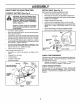
ASSEMBLY HOW TO SET UP YOUR TRACTOR CONNECT BATTERY INSTALL SEAT (See Fig. 3) Adjust seat before tightening adjustment bolt. (See Fig. 2) nals by allowing a wrench or any other CAUTION: Do notboth short battery termiobject to contact terminals at the same time. Before connecting battery, remove metal bracelets, wristwatch bands, rings, etc. Positive terminal must be connected first to prevent sparking from accidental grounding. ° • Lift hood to raised position.
INSTALL MOWER AND DRIVE BELT (See ,, Be sure tractor is on level surface and mower suspension arms are raised with attachment lift control, Engage parking brake,, o Figs. 6 and 24) ° • Cut and remove ties securing anti-sway bar and belts. Swing anti-sway bar to left side of mower deck. Slide mower under tractor with discharge guard to right side of tractor° IMPORTANT: CHECK BELT FOR PROPER ROUTING IN ALL MOWER PULLEY GROOVES INSTALL BELT INTO ENGINE PULLEY GROOVE.
ASSEMBLY _ INSTALL MLILCHER Install two latch hooks to muloher plate using screw, washer, lock washer, and weld nut as shown. NOTE: Pre-assemble weld nut to latch hook by inserting weld nut from the top with hook pointing down. o Tighten hardware securely° • Raise and hold deflector shield in upright position. • Place front of mulcher plate over front of mower deck opening and slide into place, as shown, • Hook front latch into hole on front of mower deck.
i.u.lu i i .i, ................. ii,.r, i i .................. OPERATION ,.., H'M "uml These symbols may appear ............. "_t on your tractor or in literature supplied with the product,, 'H ',', ' Learn and understand 'n' ' ,un,ulum their meaning.
i , , n lul=,=,,i,, ii ii, ,i =1= n n OPERATION _=LJl KNOW YOUR TRACTOR READ THIS OWNER'S MANUAL AND SAFETY RULES BEFORE OPERATING YOUR TRACTOR Compare the illustrations with your tractor to farniliarize yourself with the locations of various controls and adjustments, this manual for future referenceo ATTACHMENT CLUTCH LEVER Save LIGHT SWITCH POSITION IGNITION SWITCH AMMETER CHOKE ,," •" _ • " "" LIFT LEVER " PLUNGER THROTTLE CONTROL ATTACHMENT LIFT LEVER CLUTCH/BRAKE PEDAL
OPERAT!O .... i,,,i I ,111,1 i ,,, .... ..... The operation In severe eye or performing spectacles or i,,,i,,,,,,,11,,,i i ...... ,,,,,,,,,,_, ,,,,,,,,, , ,................ .... ,,,,,,,,,,,, ,, ,, ,,,. , of any tractor can result in foreign objects thrown into the eyes, which can result damage. Always wear safety glasses or eye shields while operating your tractor any adjustments or repairs, We recommend a wide vision safety mask over the standard safety glasses.
=l= OPERATION ,J,,,,, o "ENGAGED" POSITION ATTACHMENT LIFT LEVER HIGH POSITION ATTACHMENT CLUTCH LEVER '=DISENGAGED" POSITION o o POSITION = ................................... Move gearshift lever to 1st gear. Be sure you have allowed room for tractor to roll slightly as you restart movement. To restart movement, slowly release parking brake and clutch/brake pedal. Make all turns slowly° TO TRANSPORT • Raise attachment lift to highest position with attachment lift control.
OPERATION i ......................... TO START ENGINE ii, , i iiii1,1111ii ii (See Fig. 8) • When starting the engine for the first time or if the engine has run out of fue!, it will take extra cranking time to move fuel from the tank to the engine. • Sit on seat in operating position, depress clutch!brake pedal and set parking brake_ , P_ace gear shift lever in neutral (N) position. • Move attachment clutch to "DISENGAGED" position.
CUSTOMER ESPONSIBILmES ,,: , ............................ i,,,,11 MAINTENANCE , SCHEDULE RLL IN DATES AS YOU COMPLETE REGULAR SERVICE T SERVICE DATES Check Brake Operation i/ if Check Tfre Pressure if i_ # Check for Loose Fasteners V' R S,arpe,vReplaco'uower Blades Lub r!cat!°n, ch'a'rt" T 0 Check Battery LeveVRecharge ..................... ,,,,,C lean Battery and Terminals a Check Transaxle _ , ,,_, Cooling V', v" v', v' v', v' v' I_ .................
i i ii i,i i,,,,,,,i,i i CUSTOM ESPO ILITIES i iii,i ,,i ,, ,,11 , TRACTOR TO SHARPEN Always observe safety rules when performing any mainte- Care should be taken to keep the blade balanced° An unbalanced blade wilfcause excessive vibration and eventual damage to mower and engine.
CUSTO BILITIES V-BELTS AIR SCREEN Check V-belts for dete rioration and wear after 100 hours of operation and replace if necessary. The betts are not adjustable. Replace belts if they begin to slip from wear. TRANSAXLE OIL DRAIN PLUG COOLING Keep transaxle free from build-up of dirt and chaff which can restrict cooling. ENGINE OIL FILL CAP/DIPSTSICK LUSRUCATION FIG.
iiiiii,it i,ii 1,1,1111,, ii CUSTOM i IIIM "1'11 RESPONSIBILITIES rl COVER ii1,11, iir ENGINE KNOB L ,,i i i i OIL FILTER (See Fig. 18) Replace the engine oi! filter every season or every other oit change if the tractor is used more than 100 hours in one year. WING o Unscrew old filter by turning counterclockwise. suitable container to catch oil - Apply a thin coating of new engine oil to rubber gasket on replacement oil rifler.
i ,i. ...111...1111. . i1..11 IMI $ERVIC • i . ..i.i ........ iii.....i.1..1 ..... = o o o o = .......... ......i ...................... BEFORE PERFORMING , ......................... ' ..... i_..1.._. ANY SERVICE OR ADJUSTMENTS: Place gearshift lever in neutral (N) position, Depress clutch/brake pedal fully and set parking brake. Place attachment clutch in "DISENGAGED" position. Turn ignition key "OFF" and remove key, Make sure the blades and all moving parts have completely stopped.
lUlUllnnn i fluln nlll , ,,=,= ,, , ,,,,, , ......... ............
m===_=m_m=_L II Ul,l,,j, i i i SERVICE AN , TO REPLACE UllUl MOWER ADJUSTMENTS , i UlUlll.... iiiiiir DRIVE TO REPLACE (See Fig. 26) BELT MOWER DRIVE BELT REMOVAL (See Fig,. 25) o • Roll belt over the top of L°Homandrer pulley_ ° Remove belt from engine pulley,, o Remove belt from idler pulleys_ ° Remove any dirt or grass clippings which may have accumulated around mandrers and entire upper deck surface,, BLADE Park the tractor on level surface.
TO ADJUST BRAKE (See Fig. 27) PULLEY Your tractor is equipped with an adjustable brake system which is mounted on the right side of the transaxfe. TABS IDLER if tractor requires more than six (6) feet stopping distance at high speed in highest gear, then brake must be adjusted.
SERVICE AN TRANSAXLE SHIFTER LINKAGE JUSTMENT (See Figs. 30 and 31) AND ADJUSTMENTS TO START ENGINE WITH A WEAK See Fig. 32) AD- The transaxle should be in neutral when the gear shift lever is in the neutral (N) (lock gate) pesition_ The adjustment is preset at the factory; however, if adjustment is needed, proceed as follows: o ° Make sure transaxle is in neutral (N)o Loosen two locknuts on tie rod. • Turn center rod until gearshift lever falls into neutral lock gate on fender console.
i , ,111111, i, ,,,,,Ul i , ....... RV!CE AND ADJUSTMENTS ,i ,,11 TO REPLACE ,i,lu ul i ii HEADLIGHT BULB Raise hood. Pull bulb holder out of the hole in the backside of the grill. * Replace bulb in holder and push bulb holder securely back into the hole in the backside of the grill. Close hood. INTERLOCKS ,i CHOKE CONTROL i,,,,,i,1,,,i,,,11,1 ,,u, (See Fig.
........ ,........ $ TO ADJUST 37) __ Ji,,ij i RVICE AN CARBURETOR ii, ,11,,111, NTS IMPORTANT: NEVER TAMPER WITH THE ENGINE GOVERNOR, WHICH IS FACTORY SET FOR PROPER ENGINE SPEED. OVERSPEEDING THE ENGINE ABOVE THE FACTORY HIGH SPEED SETTING CAN BE DANGEROUS_ iF YOU THINK THE ENGINE-GOVERNED HIGH SPEED NEEDS ADJUSTING, CONTACT YOUR NEAREST AUTHORIZED SERVICE CENTER/ DEPARTMENT, WHICH HAS PROPER EQUIPMENT AND EXPERIENCE TO MAKE ANY NECESSARY ADJUSTMENTS.
I"II'H' "1'"1'I'1'1II I "1 ...................... STORAG ii,,i,ii,ll,ii,i ,111 i1,1 .... , i,rl,l,ll,,,i ,i , ,,i, ill ENGINE Immediately prepare your tractor for storage at the end of the season or if the tractor wii! not be used for 30 days or more. i i,,, FUEL SYSTEM J ,,, i_ CAUTION: Never store the tractor with gasoline in the tank inside a building where fumes may reach an open flame or spark. Allow the engine to cool before storing in any enclosure.
m i_ ,, ii ,i,1,1 i,iii1,11, ,,11111, i,,nl.................. TROUBLESHOOTING PROBLEM CAUSE ii i nl POINTS CORRECTION iiii i,,, 1i,,,11,,11 Will not start 1.. 2 3. 4 5. 6. 7. Out of fuel Engine not "CHOKED" Engine flooded Badspark plug. Dirtyair filter Dirty fuel filter Water in fuel. 8.. 9. Loose or damaged wiring Carburetor out of adjustment.. 10. t. 2. 3 4. 5 6 7 properly. 8. 9 10. Engine vaives out of adjustment Fill luet tank See "TO START ENGINE" in Operation section.
TROU PROBLEM HOOT! CAUSE i ,,llllll,ll,,ini Engine continues to run when operator leaves seat with attachment clutch t ,,i i,n i, ii Faulty operator-safety i n.....................................
i,i,, i1,11,, i i, ,111,1,1,1 SERVICE NOTES ! .....
TRACTOR - - MODEL NUMBER 917.258661 SCHEMATIC BLACK RED BATTERY RED FUSE 30 AMP AMMETER (OPTIONAL) BLACK I WH_E J. ........ _G STARTER J CLUTCH 1BRAKE (PEDAL UP) L, SEAT SWITCH (NOT OCCUPIED) IGNITION SWITCH I /7 BLACK METER HOUR (OPTIONAL) eF__osP% LU BLACK (_ IGNITION UNIT j(2 CHARGING SYSTEM OUTPUT 3 AMP DC @ 3600 RPM PLUGS ON TWIN CYL.
REPAIR PARTS TRACTOR - - MODEL NUMBER 917.
REPAIR PARTS TRACTOR -- MODEL NUMBER 917.
REPAIR PARTS TRACTOR CHASSIS - - MODEL NUMBER 917.
REPAIR PARTS TRACTOR CHASSIS -- MODEL NUMBER 917.258661 AND ENCLOSURES KEY NO. PART NO, 1 2 3 4 5 9 10 11 12 13 14 17 18 20 23 25 26 159527 140356 17490612 STD551025 155272 150156X0tl STD533710 155927 145660 155936 17490608 144983X558 126938X 156437 124028X 19131312 STD541437 Chassis Drawbar Screw, Thd°, Roll. 3/8-16 x 3/4 Type TT Washer 13/32 x 3/4 x 16 Gauge Bumper HoodtDash Dash, Silkscreened Bolt, Carriage 3/8-16 x 1 Panel, Dash, LH Clip Tinnerman Grille P/L Panel, Dash, RH Screw, Thd+, Roll.
REPAIR PARTS DRIVE TRACTOR -. MODEL NUMBER 917.258661 121 ).
REPAIR PARTS TRACTOR -- MODEL NUMBER 917.258661 DRIVE KEY NO, 2 3 4 5 6 8 10 11 13 14 15 !8 19 21 22 24 25 26 27 28 29 30 31 32 34 35 36 37 38 39 40 41 42 47 48 49 50 51 52 PART NO.
REPAIR PARTS TRACTOR STEERING - - MODEL NUMBER 917.
REPAIR PARTS STEERING TRACTOR-- MODEL NUMBER KEY NO_ PART NO.
REPAIR PARTS TRACTOR - - MODEL NUMBER 917.
REPAIR PARTS TRACTOR - - MODEL NUMBER 917.258661 ENGINE KEY NO. 1 2 3 PART NO. 151273 17720410 4 5 6 7 8 10 11 12 13 14 15 16 17 23 25 26 27 29 31 32 33 34 35 37 38 149723 144069 144068 138129 150176 145552 STD551125 STD522507 272250 13280336 13200300 STD551237 17490624 156123 145996 73920600 152927 137180 153630 155971 123487X 106082X 17490512 8543R .......
REPAIR PARTS TRACTOR MOWER - - MODEL NUMBER 917.
REPAIR PARTS TRACTOR MOWER - - MODEL NUMBER 917.258661 LIFT KEY NO+ PART NO. 1 2 3 4 5 6 7 8 11 12 13 15 16 17 18 19 20 23 24 25 26 27 28 29 30 31 32 49 50 159460 159471 105767X 12000002 19211621 120183X 125631X 122365X 139865 139866 STD624008 127218 73350800 130171 73800800 139868 STD624008 1!0807X 19131016 2876H 76020308 126971X 73350600 138057 150233 140302 73540600 145212 1t0452X DESCRIPTION Wire Assy., Inner, with Plunger Shaft Asmo Lift Pin Groove E Ring #5t33-62 Washer 21/32 x I x 2I Ga.
REPAIR PARTS TRACTOR MOWER - - MODEL NUMBER 917.
REPAIR PARTS TRACTOR MOWER KEY NO. - - MODEL NUMBER 917.258661 DECK PART NO.
REPAIR PARTS TRACTOR - - MODEL NUMBER 917.258661 SEAT ASSEMBLY KEY NO. PART NO, 1 2 3 4 5 6 7 8 9 10 12 140123 140551 74760616 19131610 145006 STD541437 124181X 17490616 19131614 155925 121246X DESCRIPTION KEY NO, PART NO. Seat Bracket Pnt Pivot Seat (blk) Bolt Fin Hex 3/8-16 UNC x 1 Washer Flat I3/32 x i x 10 Ga Clip Push-In ..........
REPAIR PARTS TRACTOR - - MODEL NUMBER 917.258661 DECALS 7 17 10 9 22 19 14 13 14 2 15 KEY NO. 1 2 3 4 6 7 9 10 11 13 PART NO, 156439 273503 151299 151300 133644 150927 146709 150333 156368 146046 WHEELS KEY NO. DESCRIPTION Decal Fender Danger Sears Decal, Engine 19.
REPAIR PARTS TRACTOR PEERLESS TRANSAXLE - MODEL -- MODEL NUMBER NUMBER 917.
REPAIR PARTS TRACTOR PEERLESS REF PART NO. NO.
REPAIR PARTS TRACTOR BRIGGS & STRATTON ENGINE - - MODEL NUMBER - MODEL NUMBER 42E707, 917.258661 TYPE NUMBER 1631-01 615 q_ W24 634A 552A 668 _ @40 35 _ 615 v 33 552 9A 220 @ A 230 1 12 534 ? 219 u , 642 i,ii ill 643 535 523 ._-,.i 842 445 284A L 525 524 v _._I- __.._ ...
REPAIR PARTS TRACTOR BRIGGS & STRATTON ENGINE - - MODEL NUMBER - MODEL NUMBER 917.258661 42E707, TYPE NUMBER 1631-01 51 1358 GASKET SET 1 108 51A t'861 PUMP , ,.
REPAIR PARTS TRACTOR BRIGGS & STRATTON ENGINE - - MODEL NUMBER - MODEL NUMBER 917,258661 42E707, TYPE NUMBER 1631-01 801 783 / 802 311 803 653 209A 209 J 414 207 y 3O7 22cJ 592 52
REPAIR PARTS TRACTOR BRIGGS & STRATTON ENGINE -- MODEL NUMBER 917.258661 - MODEL NUMBER 42E707, TYPE NUMBER 3 7 1631-01 22 881 8A 9 244 10A 1!o_8OWNER'S MANUAL ! !1019 LABEL KITI lO "A"REQUIRES SPECIAL TOOLS TO INSTALL. SEE REPAIR INSTRUCTION MANUAL= 305 305 304 308A 307 308 306 .....
REPAIR PARTS TRACTOR BRIGGS & STRATTON KEY PART NOo NO, 1 2 3 4 5 5A 7 7A 8 8A 9 10 10A 11 12 497074 399265 391086 493304 493457 493458 271867 271868 495754 222892 27803 94382 94830 280225 273208 271188 271189 13 94565 15 94239 18 394028 94196 20 291675 22 94724 23 491180 24 222698 25 498584 498585 498586 498587 26 394959 394960 394961 394962 27 263129 28 498319 391286 29 394306 397158 32 94671 33 390420 34 261528 35 65906 36 26828 40 221596 41 292260 42 494553 45 261368 46 2'13520 50 213290 51 271412 5
REPAIR PARTS TRACTOR BRIGGS & STRATTON ENGINE - - MODEL NUMBER - MODEL KEY PART NO, NO.
i i ii i r iiiiii i iiii iiii i SERVICE NOTES ' ' ii1,,1111 i, 56 i .... ...................
i i i i i = i SERVICE 57 NOTES
ii1,11111 SERVICE .................. iiiii NOTES i 58 , ...................
Z 0 I !-- ,,€ / n" LLI o / / 0 / LU LI. / ,,,€ / U) n-' / 0 / / t,/) LU 0 ,.,3 U) /o 0 0 2: I,-,, ::Z: l nO LI,.
® OWNER'S MANUAL 19.5 HP ELECTRIC START 46" MOWER 6 SPEED TRANSAXLE LAWN TRACTOR MODEL NO. 917.258661 Each tractor has its own model number. its own model number. Each engine has The model number for your tractor will be found on the model plate located Ltnder the seat.. The model number for your engine will be found on the blower housing of the engine. All parts listed herein may be ordered from any Sears, Roebuck and Co.. Service Center/Department and most Retai.I Stores.