Owner's Manual JCRAFTSMAN" I 20.0 HP ELECTRIC START 42" MOWER 6 SPEED TRANSAXLE1 LAWN TRACTOR Model No. 917.270930 • • • • Safety Assembly Operation Maintenance • Repair Parts CAUTION: Read and follow all Safety Rules and Instructions before operating this equipment. For answers to your questions about this product, Call: 1-800-659-5917 Sears Craftsman Help Line 5 am - 5 pro, Mon- Sat Seam, Roebuck and Co., Hoffman Estates, IL 60179 Visit our craftsman wabsite: www.sears.
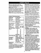
Warranty ................................................ Safety Rules .......................................... Product Specifications .......................... Assembly ............................................... Operation ............................................ Maintenance Schedule ..... i ................. LIMITED TWO YEAR WARRANTY Maintenance ....................................... 17 Service and Adjustments .................... 21 Storage ...............................................
IMPORTANT: This cutting machine is capable of amputating hands and feet and throwing objects. Failure to observe the following safety instructions could result in serious injury or death. GENERAL OPERATION • Read, understand, and follow all instructions in the manual and on the machine before starting. • Only allow responsible adults, who are familiar with the instructions, to operate the machine. • Clear the area of objects such as rocks, toys, wire, etc., which could be picked up and thrown by the blade.
• Keep children out of the mowing area and under the watchful care of another responsible adult. • Be alert and turn machine off if children enter the area. • Before and when backing, look behind and down for small children. • Never carry children. They may fall off and be seriously injured or interfere with safe machine operation. • Never allow children to operate the machine. • Use extra care when approaching blind corners, shrubs, trees, or other objects that may obscure vision.
_l, Look for this symbol to point out important safety precautions. It means CAUTION!!! BECOME AWARE!!! YOUR SAFETY IS INVOLVED. _CAUTION: In order to prevent accidental starting when setting up, transporting, adjusting or making repairs always disconnect spark plug wire and place wire where it cannot contact spark plug. _,CAUTION: Do not coast down a hill in neutral, you may lose control of the tractor.
Steering Wheel O (1) Hex Bolt 3/8-16 x 1 Steering Wheel Insert (1) Large Flat Washer (1) Locknut (1) Hex Bolt 5/16-18 x 1-1/4 [__ , 5/16-18 (1) Lockwasher 3/8 Steering Wheel [ j , Steering Boot Adapter Steering Extension Shaft C Seat (1) Washer 17/32 x 1-3/16 x 12 Gauge _(1) (1) Shoulder Bolt 5/16-18 Knob Keys Video Cassette Slope Sheet (2) Keys 6 r-1
Your new tractor has been assembled at the factory with exception of those parts left unassembled for shipping purposes. To ensure safe and proper operation of your tractor all parts and hardware you assemble must be tightened securely. Use the correct tools as necessary to insure proper tightness. Review the video cassette before you begin. TOOLS REQUIRED ASSEMBLY FOR • Assemble large flat washer, 3/8 lock washer, 3/8 hex bolt and tighten securely.
Label INSTALL SEAT Adjust seat before tightening adjustment knob. • Remove adjustment knob and flat washer securing seat to cardboard packing and set aside for assembly of seat to tractor. • Pivot seat upward and remove from the cardboard packing. Remove the carboard packing and discard. • Place seat on seat pan and assemble shoulder bolt. Tighten shoulder bolt securely. • Assemble adjustment knob and fiat washer loosely. Do not tighten. • Lower seat into operating position and sit on seat.
• Hook rear latch into hole on back of mower deck. ACAUTION: Do not remove deflector shield from mower. Raise and hold shield when attaching mulcher plate and allow it to rest on plate while in operation. Deflector Shield _ After you learn how to operate your tractor, check to see that the brake is properly adjusted. See "TO ADJUST BRAKE" in the Service and Adjustments section of this manual.
These symbols may appear on your tractor or in literature Learn and understand their meaning. BATFERY ENGINE ON FUEL ATTACHMENT CLUTCH ENGAGED IGNITION CAUTION OR WARNING ENGINE OFF CHOKE REVERSE supplied with the product.
KNOW YOUR TRACTOR READ THIS OWNER'S MANUAL OPERATING YOUR TRACTOR AND SAFETY RULES BEFORE Compare the illustrations with your tractor to familiarize yourself with the locations of various controls and adjustments. Save this manual for future reference.
The operation of any tractor can result in foreign objects thrown into the eyes, which can result in severe eye damage. Always wear safety glasses or eye shields while operating your tractor or performing any adjustments or repairs. We recommend a wide vision safety mask over spectacles, or standard safety glasses. HOW TO USE YOUR TRACTOR TO SET PARKING BRAKE Your tractor is equipped with bn operator presence sensing switch.
TO ADJUST MOWER HEIGHT TO OPERATE CUTTING The position of the attachment lift lever determines the cutting height. • Grasp lift lever. • Press plunger with thumb and move lever to desired position. The cutting height range is approximately 1-1/2 to 4". The heights are measured from the ground to the blade tip with the engine not running. These heights are approximate and may vary depending upon soil conditions, height of grass and types of grass being mowed.
TO TRANSPORT ADD GASOLINE • Raise attachment lift to highest position with attachment lift control. • When pushing or towing your tractor, be sure gearshift lever is in neutral (N) position. • Do not push or tow tractor at more than five (5) MPH. NOTE: To protect hood from damage when transporting your tractor on a truck or a trailer, be sure hood is closed and secured to tractor. Use an appropriate means of tying hood to tractor (rope, cord, etc.). • Fill fuel tank.
TO START ENGINE When starting the engine for the first time or if the engine has run out of fuel, it will take extra cranking time to move fuel from the tank to the engine. • Sit on seat in operating position, depress clutch/brake pedal and set parking brake. • Place gear shift lever in neutral (N) position. • Move attachment clutch to "DISENGAGED" position. • Move throttle control to fast position • Pull choke control out for a cold engine start attempt.
MOWING TIPS MULCHING • Mower should be properly leveled for best mowing performance. See "TO LEVEL MOWER HOUSING" in the Service and Adjustments section of this manual. • The left hand side of mower should be used for trimming. • Drive so that clippings are discharged onto the area that has been cut. Have the cut area to the right of the machine. This will result in a more even distribution of clippings and more uniform cutting.
AS YOU COMPLETE REGULAR SERVICE _ R, Y _ _O'; _'_ SERVICE DATES Check Tire PreSSure T Check Operator Presence and Interlock Systems V# R Check for Loose Fasteners if T cA 0 R I_1 I_ : Lubrication Chart V* Shat_oerdRep_ace Check Battery Level Mower Blades i4 Clean Battery and Terminals Check Transaxle Cooling I1_ Adjust Blade Bolt(s) Tension VIs Adjust Motion Drive Belt(s) Tension Check Engine Oil Level If Change EngineOil E a Clean Air Filter G Inspect E 1_1.2.
TRACTOR Always observe safety rules when performing any maintenance. BRAKE OPERATION If tractor requires more than six (6) feet stopping distance at high speed in highest gear, then brake must be adjusted. (See "TO ADJUST BRAKE" ih the Service and Adjustments section of this manual). TIRES * Maintain proper air pressure in all tires (See "PRODUCT SPECIFICATIONS" section of this manual). • Keep tires free of gasoline, oil, or insect control chemicals which can harm rubber.
BATTERY Your tractor has a battery charging system which is sufficient for normal use. However, periodic charging of the battery with an automotive charger will extend its life. • Keep battery and terminals clean. • Keep battery bolts tight. • Keep small vent holes open. • Recharge at 6-10 amperes for 1 hour. NOTE: The original equipment battery on your tractor is maintenance free. Do not attempt to open or remove caps or covers. Adding or checking level of electrolyte is not necessary.
ENGINE COOLING FINS Remove any dust, dirt or oil from engine cooling fins to prevent engine damage from overheating. Air guide covers must be removed. Remove side panels and hood (See "TO REMOVE HOOD AND GRILL ASSEMBLY" in the Service and Adjustments section of this manual). IMPORTANT: Petroleum solvents, such as kerosene, are not to be used to clean the cartridge. They may cause deterioration of the cartridge. Do not oil cartridge. Do not use pressurized air to clean or dry cartridge.
CLEANING • Clean engine, battery, seat, finish, etc. of all foreign matter. • Keep finished surfaces and wheels free of all gasoline, oil, etc. • Protect painted surfaces with automotive type wax. We do not recommend using a garden hose to clean your tractor unless the electrical system, muffler, air filter and carburetor are covered to keep water out. Water in engine can result in a shortened engine life.
TO LEVEL MOWER HOUSING • Before making any necessary adjustments, check that both front links are equal in length. Both links should be approximately 10-3/8". • If links are not equal in length, adjust one link to same length as other link. • To lower front of mower loosen nut "E" on both front links an equal number of turns. • When distance "D" is 1/8" to 1/2" lower at front than rear, tighten nuts "F" against trunnion on both front links.
BELTINSTALLATION- TO REPLACE • Install new belt in reverse order of removal. • Make sure belt is in all pulley grooves and inside all belt guides. • Install mower in reverse order of removal instructions. Park the tractor on level surface. Engage parking brake. For assistance, there is a belt installation guide decal on bottom side of left footrest. • Remove mower (See "TO REMOVE MOWER" in this section of this manual.) • Remove belt from stationary idler and clutching idler.
Gearshift Lever Neutral Lock Gate STEERING WHEEL If steering wheel crossbars are not horizontal (left to right) when wheels are positioned straight forward, remove steering wheel and reassemble per •instructions in the Assembly section of this manual. FRONT WHEEL ENGINE WITH TOE-IN/CAMBER TO ATTACH JUMPER CABLES • Connect each end of the RED cable to the POSITIVE (+) terminal of each battery, taking care not to short against chassis.
REPLACING TO REPLACE BATTERY _CAUTION: Do not short battery terminals by allowing a wrench or any other object to contact both terminals at the same time. Before connecting battery, remove metal bracelets, wristwatch bands,rings,etc. Positive terminal must be connected first to prevent sparking from accidental grounding. • Lift hood to raised position. • Remove terminal guard. • Disconnect BLACK battery cable then RED battery cable and carefully remove battery from tractor.
TO ADJUST CHOKE CONTROL The choke control has been preset at the factory and adjustment should not be necessary. Check adjustment as described below before loosening cable. If adjustment is necessary, proceed as follows: • With engine not running, move choke control (located on dash panel) to full choke position. • Remove air cleaner cover, filter and cartridge plate to expose carburetor choke (see "AIR FILTER" in the Maintenance section of this manual). • Choke should be closed.
Immediately prepare your tractor for storage at the end of the season or if the tractor will not be used for 30 days or more. _I_kCAUTION" Never store the tractor with gasoline in the tank inside a building where fumes may reach an open flame or spark. Allow the engine to cool before storing in any enclosure. TRACTOR Remove mower from tractor for winter storage. This will allow you to clean it thoroughly. Remove all dirt, grease, leaves, etc. Store in a clean, dry area.
TROUBLESHOOTING CHART PROBLEM CAUSE Willnotstart • Out of fuel. • Engine not"CHOKED" properly. • Engine flooded. CORRECTION • Engine valves out of adjustment. • Fill fuel tank. • See "TO START ENGINE" in Operation section. • Wait several minutes before attempting to start. • Replace spark plug. • Clean/replace air filter. • Replace fuel filter. • Drain fuel tank and carburetor, refill tank with fresh gasoline and replace fuel filter. • Check all wiring.
TROUBLESHOOTING CHART PROBLEM CAUSE CORRECTION Engine clicks but will not start (cont'd) i • Loose or damaged wiring. _• Faulty solenoid or starter. • Check all wiring. • Check/replace solenoid or starter. • Cutting too much grass/ too fast. • Throttle in "CHOKE" position. • Build-up of grass, leaves and trash under mower. • Dirty air filter. • Low oil level/dirty oil. • Faulty spark plug. • Set in "Higher Cut" position/ reduce speed. • Adjust throttle control. Loss of power • Dirty fuel filter.
TROUBLESHOOTING CHART PROBLEM CAUSE CORRECTION Poor cut - uneven (cont'd) • Clogged mower deck vent holes from buildup of grass, leaves, and trash around mandrels. • Clean around mandrels to open vent holes. Mower blades will not rotate • Obstruction in clutch mechanism. • Worn/damaged mower drive belt. • Remove obstruction. • Replace mower drive belt. • Frozen idler pulley. • Frozen blade mandrel. • Replace • Replace idler pulley. blade mandrel. Poor grass discharge • Engine speed too slow.
SCHEMATIC BA'I-rERY .Eo "ED FUSE AMMETER (OPTIONAL) _[_ w.,T. ...... I RE_ i A1 (PEDAL STARTER au,oc I I L CLUTCH/BRAKE )G _1_ ,'©' J I UP) SOLENOID I IGNITION SWITCH WNITE ..... WHIT E (NOT OCCUPIED) I I I_ BLACK ' I I © (_) I _. l _. SEAT SWITCH i I J BLACK L ' I BLACK BUICK (CLUTCH OFF) (OPTIONAL) ! GROUNDING CONNECTOR J W EUEL_ BUicK (_ IGNITION UNIT 1 SPARK _• f_ I 28 VOLTS PLUG GAP • r • I BLUE 'l LINE _ i TWIN CYL.
TRACTOR - MODEL NUMBER 917.
TRACTOR - MODEL NUMBER 917.270930 ELECTRICAL KEY NO. 1 2 8 10 11 12 16 21 22 24 25 26 27 28 29 30 33 40 41 42 43 45 52 55 PART NO.
TRACTOR - MODEL CHASSIS AND ENCLOSURES NUMBER 917.
I rt/-t_, I url -- IVlUUr..I- NUMUt'H _]/',;_/U_JU :HASSIS AND ENCLOSURES KEY PART NO, NO.
TRACTOR GROUND - MODEL NUMBER 917.270930 DRIVE 57 116 150 • 48 151 51 25 53 96 .
I HP,_ IUH -- MUUI¢L GROUND NUMHp..H 917.270930 DRIVE KEY PART NO. NO. 1 ........
I I'i/-_l.p I Url _ NIUUI=I. NUMI31=M _ I I.
TRACTOR - MODEL NUMBER 917.270930 _TEERING KEY PART NO. NO. DESCRIPTION 1 2 3 4 5 6 7 8 9 10 11 13 15 17 18 19 22 23 26 26 27 28 29 30 32 36 37 38 39 40 41 42 43 44 46 47 51 54 62 63 65 66 67 68 79 80 82 85 Steering Wheel Axle AssemblySTMP DroppedSTL Spindle Assembly,L.H. Spindle Assembly, R.H.
TRACTOR - MODEL NUMBER 917.
TRACTOR - MODEL NUMBER 917.270930 -'NGINE KEY NO. 1 2 3 4 5 6 7 8 10 11 12 13 14 15 16 17 23 25 26 27 29 31 32 33 34 37 38 39 45 81 PART NO. 162152 17720410 149723 144069 144068 138129 150176 145552 STD551125 STD522507 165287 13280336 13200300 STD551237 17490624 169837 145996 73920600 152927 137180 157103 161696 123487X 106082X 8543R ....... 109227X 17000612 73510400 DESCRIPTION Control, Throt Paddle 32 22 Screw, Hex Thd Cut 1/4-20 x 5/8 Engine, B&S, (See Breakdown) No.
TRACTOR - MODEL NUMBER 917.270930 SEAT ASSEMBLY 5 25 • d "% • #$ 11 I 17 KEY PART NO. NO, 1 140123 2 140551 3 71110616 4 19131610 5 145006 6 STD541437 7 124161X 8 17000616 9 19131614 10 155925 11 166369 12 121246X i 12 KEY NO. DESCRIPTION Seat 3350 BIk/blk Craftsman Bracket Pnt Pivot Seat (blk) Bolt Fin Hex 3/6-16unc X 1 Washer 13/32 X 3/4 X 16 Ga Clip Push In Hinged Nut Hex Lock w/Ins 3/9-16 Unc Spring Seat Cprsn 2 250 BIk Zi Screw 3/8-16 x 1.
TRACTOR -- MODEL NUMBER 917.270930 DECALS 3 8 19 7 7 13 q 15 KEY PART NO. NO. DESCRIPTION 1 2 3 4 5 6 7 8 9 11 Decal, Fender Danger Sears Decal, Engine Decal, Hood, R.H. Decal, Hood, L.H. Decal, Fender Decal, Maintenance Decal, Panel Dash B&S Decal, Rplcmnt Decal, Fender, Craftsman Decal, Fender STLT Oper Inst E/S 156439 165407 171696 171697 163207 133644 163257 171808 163204 156368 WHEELS 2 _ KEY PART NO. NO.
I li-I/"S,_ I _4,Jl'i -- IVI_,$ULT, L,.
TRACTOR -- MODEL NUMBER 917.270930 JFT ASSEMBLY KEY NO. 1 2 3 4 5 6 7 8 11 12 13 15 16 17 16 19 20 31 32 PART NO. 159460 159471 105767X 12000002 19211621 120183X 125631X 122365X 139865 139866 STD624008 173268 73350800 130171 73800800 139868 163552 169865 73540600 NOTE: DESCRIPTION Lift Lever Inner Wire Assembly Shaft Assembry, Lift Pin, Groove E-Ring Washer 21/32 x 1 x21 Gauge Bearing, Nylon Grip, Handle, Fluted Button, Plunger, Red Link, Lift, L.H. Link, Lift, R.H.
TRACTOR - MODEL NUMBER 917.
TRACTOR -- MODEL NUMBER 917.270930 MOWER DECK KEY PART NO. NO.
TRACTOR PEERLESS - MODEL NUMBER TRANSAXLE--MODEL NUMBER 917.
TRACTOR -- MODEL NUMBER 917.270930 EERLESS _EY PART IO. NO. 0 1 2 3 772147 780086A 770128 776395 776409 778364 778369 778330 792180 792047 784352 784378 778334 778309 778368 4 778368 5 7 8 0 1 2 5 5A 6 7 8 9 778370 786188 786102 792077A 792078 792079 792073A 792177 792125 792035 788040 780072 A A 9A 780160 9B 780051 3C 780199 780108 l 780001 I A 780195 788083 780194 780193 _A 780197 790075 7 790007 3 799021 TRANSAXLE--MODEL NUMBER 206-545C KEY PART NO. NO.
TRACTOR - MODEL NUMBER 917.270930 BRIGGS & STRATrON ENGINE-MODEL NUMBER 461707, TYPE NUMBER 0145-E3 8811 5 I_-"_-_ 523 I 41 _ --/ 177 1125 '_ 449 1081 o 634 552A 552 404 o 1095 VALVE OVERHAUL GASKET 7i SET 74;_ _! 220 !_L ( , J 46 11019 11058 1132 LABEL OWNER'S KIT I MANUAL REQUIRES SPECIAL TOOLS TO INSTALL. SEE REPAIR INSTRUCTION MANUAL.
TRACTOR -- MODEL NUMBER 917.270930 BRIGGS & STRATTON ENGINE-MODEL NUMBER 461707, TYPE NUMBER 0145-E3 861 PUMP REPAIR KIT 392_ 432_ 386!_ 877 ik REQUIRES SPECIAL TOOLS TO INSTALL. SEE REPAIR tNSTRUCTtON MANUAL.
TRACTOR - MODEL NUMBER 917.
TRACTOR -- MODEL NUMBER 917.270930 tRIGGS & STRATTON ENGINE-MODEL NUMBER 461707, TYPE NUMBER 0145-E3 _EY 10. I PART NO. DESCRIPTION 3 498583 399265 391086 493304 Cylinder Assembly Bushing/Seal Kit Seal-Oil Sump-Engine _r A P A ) 691162 691163 271867 271868 495754 Head-Cylinder #1 Head-Cylinder #2 -k.
TRACTOR BRIGGS & STRATrON KEY NO. PART NO.
SUGGESTED I GUIDE FOR SIGHTING SLOPES ONLY RIDE UP AND DOWN HILL, NOT ACROSS HILL "" SIGHTING IIDE ol o'1 FOR SAFE OPERATION SIGHT AND HOLD THIS LEVEL WITH SKY LINE OR TREE. 15 ° MAX. ! Operate your Tractor up and down the face of slopes (not greater than 15°), never across the face. Make turns gradually to prevent tipping or loss of control. Exercise extreme caution when changing direction on slopes.
ii̧ For repair of major brand appliances in your own home... no matter who made it, no matter who sold it! 1-800-4-MY-HOME SM Anytime, day or night (1-800-469-4663) www.sears.com To bring in products such as vacuums, lawn equipment and electronics for repair, call for the location of your nearest Sears Parts & Repair Center. 1-800-488-1222 Anytime, day or night www.sears.