Owner's Manual JCRRFT$1VlRN® J 20.0 HP ELECTRIC START 46" MOWER 6 SPEED GARDEN TRACTOR Model No. 917.272955 • Safety • Assembly • Operation • Maintenance • Repair Parts CAUTION: Read and follow all Safety Rules and Instructions before operating this equipment. For answers to your questions about this product, Call: 1-800-659-5917 Sears Craftsman Help Line 5 am - 5 pm, Mort - Sat SEARS, ROEBUCK AND CO., HOFFMAN ESTATES, IL 60179 Visit our Craftsmanwebsite:www.sears.
Warranty ............................................... 2 Safety Rules ......................................... 3 Product Specifications .......................... 6 Assembly .............................................. 8 Operation ............................................ 12 Maintenance Schedule ...................... 18 Maintenance ....................................... 18 Service and Adjustments .................... 22 Storage ............................................... 29 Troubleshooting ..
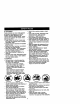
MPORTANT: This cutting machine is capable of amputating hands and feet and throwing objects. Failure to observe the following safety instructions could result in serious injury or death. I. GENERAL OPERATION II. SLOPE OPERATION • Read, understand, and follow aiI Slopes are a major factor related to loss-ofinstructionsin the manual and on the control and tipover accidents, which can remachine before starting. sult in severe in ury or death.
Ill.CHILDREN Tragic accidents can occur if the operator is not alert to the presence of children. Children are often attracted to the machine and the mowing activity. Never assume that children will remain where you last saw them. • Keep children out of the mowing area and under the watchful care of another responsible adult. • Be alert and turn machine off if children enter the area. • Before and when backing, look behind and down for small children. • Never carry children.
• Useslowspeed. Choose alow gear so that you will not have to stop or shift while on the slope. • Avon starting or stopping on a slope. II tires lose traction, disengage the blades and proceed slowly straight down the slope. • If machine stops while going uphill, disengage blades, shift into reverse and back down slowly. • Do not turn on slopes unless necessary, and then, turn slowly and gradually downhill, if possible. _Look for this symbol to point out important safety precautions.
PRODUCT SPECIFICATIONS GASOLINE 3.5GALLONS CAPACITY UNLEADED ANDTYPE: REGULAR Z)ILTYPE API-SF-SJ): )IL CAPACITY: SAE 10W30 (ABOVE 32°F) SAE 5W-30 (BELOW 32°F) W/FILTER: 4.5PINTS W/O FILTER: 4.0PINTS SPARK PLUG: CHAMPION 3AP: .030") RC12YC GROUND SPEED LO: HI: (MPH): 0.7 1.7 1.4 3.3 2.3 5.4 REVERSE: 0.9 2.1 TIRE PRESSURE: FRONT: REAR: CHARGING SYSTEM: BATTERY: 15AMPS @ 3600RPM BLADE BOLT TORQUE: 14 PSI f 0 PSI AMP/HR: 35 MIN. CCA: 280 CASE SIZE:UlR 27-35 FT.
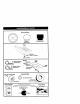
Steering Wheel Steenng Sleeve Wheel Insert Seat (1) Washer 17/32 x 1-3/16 x 12 Gauge _(1) Knob Mower (5) Retainer Spdngs (2)Flanged 12) Retainer Spdngs _(smgle loop) (1)Front Plate Assembly _ -% ) Shoulder Bo_ts "_,_/'(2) © Gauge Wheels Wheels 3/8 x 3/4 x 14 Ga_ Video Cassette I_ For Future Use I_-- Keys (2) Keys 7 Slope Sheet I I
Your new tractor has been assembled at the factory with exception of those parts left unassem_ed tor shipping purposes. To ensure safe and proper operation of your tractor all parts and hardware you assemble must be tightened securely. Use the correct tools as necessary to insure proper tightness• TOOLS REQUIRED FOR ASSEMBLY A socket wrench set will make assembly _Wheel Insert easier. Standard wrench sizes you need I(_ _/Steertng are listed below.
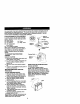
INSTALL SEAT Adjust seat before tightening adjustment knob. 1. Remove adjustment knob and flat washer securing seat to cardboard packing and set aside for assembly of seat to tractor. 2. Pivot seat upward and remove from the cardboard packing. Remove the cardboard packing and discard. 3. Place seat on seat pan so head of shoulder bolt is positioned over large slotted hole in pan. 4. Push down on seat to engage shoulder bolt in slot and pull seat towards rear of tractor. 5.
INSTALL MOWER ANDDRIVEBELT Besuretractor isonlevelsurface and mower suspension arms are raised with attachment lift control. Engage parking brake. 1. Cut and remove ties securing antisway bar and belts. Swing anti-sway bar to left side of mower deck. 2. Slide mower under tractor with deflector shield to right side of tractor. IMPORTANT: Check belt for proper routingin all mower pugey grooves. 3. If equipped, turn height adjustment knob counterclockwise until it stops.
CHECK TIRE PRESSURE The tires on your tractorwere ovennflated at the factoryfor shippingpurposes. Correcttire pressure is importantfor best cutting performance. • Reduce tire pressure to PSI shown in "PRODUCT SPECIFICATIONS" section of this manual. CHECK MOWER LEVELNESS For best cutting results,mower should be propedyleveled. See =TO LEVEL MOWER HOUSING" in the Service and Adjustments section of this manual.
These symbols may appear on your tractor or in literature supplied with the product. Learn and undemtand their meaning. BATTERY CAUTION OR WARNING REVERSE ENGINE ON ENGINE OFF OIL PRESSURE LIGHTS ON OVER TEMP LIGHT FUEL CHOKE MOWER HEIGHT PARKING BRAKE LOCKED UNLOCKED ATrACHMENT CLUTCH ENGAGED IGNITION DANGER.
KNOWYOURTRACTOR READ THIS OWNER'S MANUAL AND SAFETY RULES BEFORE OPERATING YOUR TRACTOR Compare the illustrationswith your tractor to familiarize yourself with the locations of various controls and adjustments. Save this manual for future reference. Ignition Switch Position Ammeter ,Attachment ;lutch Switch Throffie Control Plunger Clutch/Brake Attachment Lift Lever Broke Control 3 Shitt Lever Adjustment Knob \ Gear ShiftLever Our tractors conform to the safety standards of the American National
The operation of any tractor can result in foreign objects thrown into the eyes, which can result in severe eye damage. Always wear safety glasses or eye shields while operating your tractor or performing any adjustments or repairs. We recommend a wide vision safety mask over spectacles or standard safety glasses. HOWTO USEYOURTRACTOR TO SET PARKING BRAKE Your tractor is equipped with an operator presence sensing switch.
The cutting height range is approximately 1-1/2" to 4-1/2". The heights are measured from the ground to the blade tip with the engine not running. These heights are approximate and may vary depending upon soil conditions, height ol grass and types of grass being mowed. • The average lawn should be cut to approximately 2-1/2 inches during the cool season and to over 3 inches dudng hot months. For healthier and better looking lawns, mow often and after moderate growth.
TOWING CARTS AND OTHER ATTACHMENTS Tow only the attachments that are recommended by and comply with specificationsof the manufacturer of your tractor. Use common sense when towing. Too heavy of a load, while on a slope, is dangerous. Tires can lose traction with the ground and cause you to lose control of your tractor. BEFORE STARTING THE ENGINE CHECK ENGINE OIL LEVEL The engine in your tractor has been shipped, from the factory, already filled with summer weight oil 1.
WARM WEATHER STARTING (50 ° F and above) 7. When engine starts, stowly push choke control in until the engine begins to run smoothly. If the engine starts to run roughly, pull the choke control out slightly for a few seconds and then continue to push the control in slowly. • The attachments and ground drive can now be used. If the engine does not accept the load, restart the engine and allow it to warm up tor one minute using the choke as deecdbed above. COLD WEATHER STARTING (50 ° F and below) 7.
MAINTENANCE SCHEDULE _"_/'_'_ "_'_/_/.,_¢_ '' DATES _/ Check T A, I_rat or pre_ne.e _ Intedock Systems Chock forLoose FaS_r. Sh_pe,'VRep_ace Mowar Blades Lubrk_t_n /// J I/'7 emil _ T Check BatteryLevel R Clean _tte W and Te,l_lnals Check Trans_xle IbS I_ Cooling •_iust e_ad8 BeR(s)Ter.s_n l,/s Adjust Motion Drive Belt(s) Ten.
TRACTOR Always observe safety rules when performing any maintenance. BRAKE OPERATION If tractor requires more than six (6) feet stopping distance at high speed in highest gear, then brake must be adjusted. (See "TO ADJUST BRAKE" in the Service and Adjustments section of this manual). TIRES • Maintain proper air pressure in all tires (See "PRODUCT SPECIFICATIONS" section of this manual). • Keep tires free of gasoline, oil, or insect control chemicals which can harm rubber.
BATrERY Yourtractor has a battery charging system which is sufficient for normal use. However, periodic charging of the battery with an automotive charger will extend its life. • Keep battery and terminals clean. • Keep battery bolts tight. • Keep small vent holes open. • Recharge at 6-10 amperes for I hour. NOTE: The original equipment battery on your tractor is maintenance free. Do not attempt to open or remove caps or covers. Adding or checking level of electrolyte is not necessary.
Oil Drain Valve oap DrainTube/ _losed and LockedPosition CLEAN AIR SCREEN Air screen must be kept free of dirt and chaff to prevent engine damage from overheating. Clean with a wire brush or compressed air to remove dirt and stubborn dried gum fibers. CLEAN AIR INTAKE/COOLING AREAS To insure proper cooling, make sure the grass screen, cooling fins, and other external surfaces of the engine are kept clean at all times.
CLEANING • Clean engine, battery, seat, finish, etc. of all foreign matter. • Keep finished surfaces and wheels free of all gasoline, oil, etc. • Protect painted surfaces with automotive type wax. We do not recommend using a garden hose to clean your tractor unless the electrical system, muffler,air filter and carburetor are covered to keep water out. Water in engine can result in a shortened engine life. CAUTION: BEFORE PERFORMING ANY OR ADJUSTMENTS: 1.
SIDE-TO-SIDE ADJUSTMENT • Raise mower to its highest position. • Measure height from bottom edge of mower to ground level at front corners of mower. Distance "A" on both sides of mower should be the same. • If adjustment is necessary, make adjustment on one side of mower only. • To raise one side of mower, tighten lift link adjustment nut on that side. • To lower one side of mower, loosen lift link adjustment nut on that side. NOTE: Each full turn of adjustment nut will change mower height about 3/16".
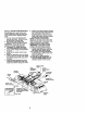
r-w_t Left _ Hand ManOdrel'l'l _ Screws Left Hand I Mandre Idler Electric Left Hand Clutch Mandrel Mower Blade Belt Center Mandrel Mandrel Cover _ Mower • Drive Secondar Idler Arm. Mower Drive Belt B_ Keepers TO REPLACE MOWER BLADE DRIVE BELT Park the tractor on level surface. Engage parking brake. 1. Remove mower drive belt (See "TO REPLACE MOWER DRIVE BELT" in this section of this manual). 2. Remove mower (See "TO REMOVE MOWER" in this section of this manual). 3. Remove screws from R.H.
4. Road test tractor for proper stopping distance as stated above. Readjust if necessary. If stoppingdistance is still greater than six (6) feet in highestgear, further maintenance is necessary. Contact a Sears or other qualified service center. WITH PARI BRAKE "ENGAGED" Nut =A" Arm TO REPLACE MOTION DRIVE BELT Park the tractor on level surface. Engage parking broke. For ease of service there is a belt installationguide decal on bottom of left footrest. It is not necessary to remove mower.
FRONT WHEEL CAMBER The front wheel camber is not adjustable on your tractor. If damage has occurred to affect the front wheel camber, contact a Sears or other qualified service center. TO REMOVEWHEEL FOR REPAIRS FRONT WHEEL 1. Block up axle securely. 2. Remove axle cover, retaining ring and washers to allow wheel removal. 3. Repair tire and reassemble. 4. Replace washers and snap retaining ring securely in axle groove. 5. Replace axle cover. REAR WHEEL 1. Block rear axle securely. 2.
7. Connect BLACK grounding cable to negative (-) battery terminal with remaining hex bolt and keps nut. Tighten securely 8. Close terminal access doors. 9. Close hood. Hex Bolt Keps Terminal Access_ Door Cable Terminal Guard (Black) Cable TO REPLACE HEADLIGHT BULB 1. Raise hood. 2. Pull bulb holder out of the hole in the backside of the grill. 3. Replace bulb in holder and push bulb holder securely back into the hole in the backside of the grill. 4. Close hood.
Idle Fuel Adjusting Adjusting Screw Control Cable Control Cable TO ADJUST CHOKE CONTROL The choke control has been preset at the factory and adjustment should not be necessary, check adjustment as described below before loosening cable. If adjustment is necessary, proceed as follows: 1. With engine not running, move choke control (located on dash panel) to full choke position. 2.
Immediately prepare your tractor for storage at the end of the season or if the tractor will not be used for 30 days or more. A CAUTION: Never store the tractor with gasoline in the tank inside a building where fumes may reach an open flame or spark. Allow the engine to cool before storing in any enclosure. TRACTOR Remove mower from tractor for winter storage. When mower is to be stored for a period of time, clean it thoroughly, remove all dirt, grease, leaves, etc. Store in a clean, dry area. 1.
TROUBLESHOOTING CHART PROBLEM CAUSE Wlllnotatart 1. Outoffuel, 2. Engine not "CHOKED" properly. 3. Engine flooded. 4. 5. 6. 7 Bad spark plug. Dirty air filter. Dirty fuel filter. Water in fuel. 8. Loose or damaged wiring. 9. Carburetor out of adjustment. 10. Engine valves out of adjustment. Ha_ _ sta_ 1. Dirty air filter. 2. Bad spark plug. 3. Weak or dead battery. 4. Dirty fuel filter. 5. Stale or dirtyfuel. 6. Loose or damaged wiring. 7. Carburetor out of adjustment. 8.
TROUBLESHOOTING PROBLEM Lose_power CHART CAUSE CORRECTION 1. Cuttingtoomuchgras_oo fast. 2. Throttle in =CHOKE" position. 3. Build-up of grass, leaves and trash under mower. 4. Dirty air filter. 5. Low oil level/dirty oil. 6. Faulty spark plug. 7. Dirty fuel filter. 8. Stale or dirty fuel. 9. Water in fuel. lO.Spark plug wire loose. 11. Dirty engine air screen/fins. 12. Dirty/clogged muffler. 13.Loose or damaged wiring. 14.Carburetor out of adjustment. 15.Engine valves out of adjustment.
TROUBLESHOOTING • ROBLEM Vtowerbladeswlll lot rotate Poor grass discharge -leadllght(s) not working 'If so equipped) CHART CAUSE 1, Obstruction in clutch mechanism. 2. Worn/damaged mower drive belt. 3. Frozen idler pulley. 4. Frozen blade mandrel. 3. Replace idler pulley. 4. Replace blade mandrel. 1. Place throttle control in "FAST" position. 2. Shift to slower speed. 2. Travel speed too fast. 3, Allow grass to dry before 3. Wet grass. mowing. 4. Level mower deck. 4. Mower deck not level. 5.
TRACTOR -- MODEL NUMBER 917.272955 SCHEMATtC BAI_ERY AMMETER F_S_ (OPTIONAL) I _ - " _,_, -- I"_ SOLENOID m STARTE_ _ R ' ',c G' • i .... _, "_ i .!o!o: _I FUEL i LINE i -- SPARK P'LUGS SQ.EN_O A sw_,_uo_rr p_ PTO SWITCH IGNITION HEAOL_HTS L'°::" I,::?Z. I swrrcH ] o;_. Ic * F_B+E,A +O I RELAY GFC WIRING _SU_TED CUPS HOt'E: IF WIRING IHS'Ot J_TED CUPS WERE REMOVED FOR SERVICING OF UNIT. THEY SHOULO BE REPLACED TO PROPERLY SECURE YOUR WIRING.
TRACTOR - - MODEL NUMBER 917.
TRACTOR -- MODEL NUMBER 917.272955 ELECTRICAL KEY NO. PART NO.
TRACTOR - - MODEL NUMBER 917.
TRACTOR - - MODEL NUMBER 917.272955 CHASSIS AND ENCLOSURES KEY NO. PART NO.
TRACTOR - - MODEL NUMBER 917.
TRACTOR o° MODEL NUMBER 917,272955 GROUND DRIVE KEY NO.
TRACTOR - - MODEL NUMBER 917.272955 STEERINGASSEMBLY 23 34 32 6 27 42 lS "\ 40
TRACTOR - - MODEL NUMBER 917.272955 STEERINGASSEMBLY KEY PART NO. NO. DESCRIPTION 1 2 3 4 5 6 7 8 9 10 11 12 13 14 15 16 17 18 19 20 21 22 23 24 25 26 27 28 29 31 32 33 34 35 36 37 38 39 40 41 42 Wheel,Steering Axle Asm., Front Fitting, Grease Spindle Asm, LH Spindle Asm., RH Bearing, Race Thrust Harden Washer 25/32 x 1-5/8 x 16 Ga. Ring, Klip #T5304-75 Cap, Spindle Belt, Fin Hex 5/8-11 x 2-3/4 Spacer Bearing Axle Front Nut, Lock Flange 5/8-11 Uric Washer 25/32 x 1-1/4 x 16 Ga.
TRACTOR - - MODEL NUMBER 917.272955 ENGINE 25_ 6g 81 18 15 17 37 29 \ 16 39 KEY NO. PART NO. 1 ...... 2 8 9 10 11 12 15 16 17 18 20 21 22 24 25 26 27 28 29 35 I SPARK DESCRiPTiON Engine (See Breakdown) )
TRACTOR --MODEL NUMBER 917.272955 SEAT ASSEMBLY 21 KEY NO. 1 2 3 4 5 5 7 8 10 12 13 14 PART NO. 140123 140551 140675 127018X 145006 STD541437 124181X 171877 174694 121246)( 121248X 72050412 DESCRIPTION Seat Bracket, Pivot Sest Strap, Fender Bolt, Shoulder 5/16-18 x .62 Clip, Push In, Hinged Nut, Crownlock 5/8-16 Unc Spr;ng, Seat Cprsn Bolt 5/16-18Uncx 5/4 w/Seres Pan, Seat Bracket, Mounting Switch Bushing, Snap Bolt, Cardage 1/4-20 X 1-1/2 KEY NO. PART NO.
TRACTOR - - MODEL NUMBER 917.272955 DECALS 15 10 8 19 12 1 1617 I_'Y NO. 1 2 3 4 5 PART NO. 172507 164085 1717(}2 17170_ 149516 6 7 8 9 10 11 133644 163210 171705 16..'_04 156439 4900J DESCRIPllON Decal. DBsh Panel Decal, Dash Decal, Hood, Craftsman, RH Decal, Hood. Craftsman, LH Decai, Battenj DNGWPSN ENG Asm Decal,Maintenance Decal Fender Decal SD, PNL Decal. Fender, Craftsman Decal, Fender Danger Decal, Clutch/Brake WHEELS &TIRES 4 7 10 KEY NO. pART NO.
TRACTOR -- MODEL NUMBER 917.272955 LIFTASSEMBLY 4O 39 KEY NO. PART NO. DESCRIPTION 1 2 3 4 5 6 7 8 9 10 11 12 13 14 15 16 16 19 20 21 23 24 121006X 177535 169189 12000(_2 19292016 71110624 125631X 1223,_X 122364X 2876H 146704 163552 13_68 169865 ETD541437 674A247 143363 STETo51037 5328J STD523710 STD624008 733508(_ Rod Asm., Lever Shaft Asm., Lift Vgt Lever Asm.
TRACTOR - - MODEL NUMBER 917.
TRACTOR -- MODEL NUMBER 917.272955 MOWERDECK KEY NO. 1 3 5 6 8 9 10 11 13 14 15 16 18 19 20 21 22 23 24 25 26 27 28 29 30 31 32 33 34 35 36 PART NO. 156948 138457 S_40_8 130832 DESCRIPTION DeckWeldment Bracket Asm., Sway Bar Retainer Spring Arm, Suspension, Rear (Sway Bar) 850857 Bolt, Patched 3/8-24 x 1-1/4 Gr. 8 STD551137 Washer, Lock Hvy., Unplated 3/8 14(_LxJ6 Washer, Hard Blede, Mower Vented 176084 Blade 137553X900 Shaft Asm.
TRACTOR - - MODEL NUMBER 917.
TRACTOR - - MODEL NUMBER 917,272955 TRANSAXLE KEY NO. PART NO.
TRACTOR - - MODEL NUMBER 917.272955 KOHLER ENGINE-MODEL NUMBER CV20,TYPE NUMBER65566 CYLINDER HEAD, VALVE AND BREATH ER I _113 \ _I, F:_ _,, 74 23_24 e--O 22- -7 V I t 0--21 ? 18_ --19 7__ 1 OD8 5O _'--20 2S._.
TRACTOR -- MODEL NUMBER 917.272955 KOHLER ENGINE-MODEL NUMBER CV20,TYPE NUMBER 65566 HEAD/VALVE/BREATHER CRANKCASE KEY NO. KEY PART NO. NO. PART NO. 1 24-033-03-S 2 3 4 24-041-23-S 24-096-59-S M-645020 5 6 7 8 9 10 11 12 13 14 15 16 17 18 19 20 21 22 23 24 25 26 27 28 29 30 31 32 33 34 35 36 37 DESCRIPTION 24-032-01-S Kit, breather cover w/ gasket (Includes 2,3) Gasket, breather Cover, breather Screw, hex. flange M6xl.0x20 (4) X-75-23-S Plug, allen hd.
TRACTOR - - MODEL NUMBER 917,272955 KOHLER ENGINE-MODEL NUMBERCV20,TYPE NUMBER65566 IGNITION/ELECTRICAL I SLOWER HOUSING AND BAFFLESJ 6 AIR INTAKE I 3 11 13 52
TRACTOR-MODEL NUMBER 917.272955 KOHLER ENGINE-MODEL NUMBER CV2O, TYPENUMBER 65566 IGNITION/CHARGING BLOWER KEY NO. PART NO, KEY NO. PART NO. 1 54-755-15-S Kit, grass screen (includes 2-4,and 24 113 15) Screw, hex. cap M4x0.7x25 (4)4 Was her, plain 5/16" (4) Spacer, grass screen (4) Bolt, shoulder (4) Fan Screw, hex. flange M10x1.5x46 Washer, plain 3/8". Key Flywheel Rectifier-regulator Washer, plain 3/16" (2) Screw, phillipshe.
TRACTOR -- MODEL NUMBER 917.
TRACTOR -- MODEL NUMBER 917.272955 KOHLER ENGINE-MODEL NUMBER CV20,TYPE NUMBER65566 STARTING KEY PART NO. NO. 1 OIL pAN/LU BRtCATION SYSTEM DESCRIPTION M-839070-S 2 3 4 5 6 7 8 9 10 11 Screw, hex. flange M8x1.25x70 24o096-05-S Cover, pinion M-839080-S Screw, hex. flange MSx1.25x80 12-468-01-S Washer, plain 11/32" (3) 25-098-05-S Starter, (Includes 6-11) 12-221-01-S Kit, brush 12-227-13-S Cap 12-211-01-S Bolt,thru (2) 12.
TRACTOR -- MODEL NUMBER 917.
TRACTOR -- MODEL NUMBER 917.272955 KOHLER ENGINE-MODEL NUMBERCV2O,TYPE NUMBER 65566 FUEL SYSTEM KEY NO. PART NO. Crankshalt (Includes 2) Plug, cup 1 24-853-25-S 2 3 24-041-15-S 24-053-25-S 4 5 6 7 8 g 10 24-041-14-S M-629095-S M-641060-S 47-154-01-S 24-353-03-S X-426-9-S 24-086-12-S 11 12 13 14 24-393-16-S 24-100-01-S 15-353-04-S 24-050-02-S CRANKSHAFT KEY NO. 1 2 PART NO. 24-014-72-S 52-139-09-S DESCRIPTION EXHAUST KEY NO. PART NO.
SUGGESTED GUIDE FOR SIGHTING SLOPES FOR SAFE OPERATION ONLY RIDE UP AND DOWN HILL, NOT ACROSS HILL I I _llh r greater than 15 ), never across the face. Make turns gradually to prevent tipping or loss of control. Exerclse extreme Operate when caution your Tractor changing updirection and downonthe slopes.
For repair of major brand appl_ in your own home... no me_er who made it, no matter who sold i_ 1.800-4-MY-HOME _ (1.e00-46_4663) Ar¥_ne, daycrr_ht (U.SAandCanada) Forrepairof carry-inproductslikevacuums,lawn equipment,and e_ics, callfor thenearestSears Parts and Repair Center. 1-800-488-1222 An,pine, dayorn_t (U,SXody) wtw/Jleetll.com For the replacement parts, accessories and owner's menua}s that you need to do-it-yourself,call Sears PartsDirectSM! 1-800-366-PART (1.800-,366-7278) 6a.m.- 11p.