Owner's Manual ICReFTSMeW,, I LAWN TRACTOR 17.0 HP, 42" Mower Electric Start 6 Speed Transaxle Model No. 917.273130 IMPORTANT: Read and follow all Safety Rules and Instructions before operating this equipment. For answers to your questions about this product, Call: 1-800-659-5917 Sears Craftsman Help Line 5 am - 5 prn, Mort - Sat Sears, Roebuck and Co., Hoffman Estates, IL 60179 U.S.A. Visit our Craftsman website:www.sears.
Warranty................................................. 2 SafetyRules...........................................3 ProductSpecifications............................6 AssemblyiPre-Operation........................8 Operation.............................................. 11 MaintenanceSchedule.........................17 Maintenance.........................................17 Serviceand Adjustments......................21 Storage................................................. 27 Troubleshooting.............
IMPORTANT: This cutting machine is capable of amputating hands and feet and throwing objects. Failure to observe the following safety instructions could result in serious injury or death. • Be aware of the mower discharge direction and do not point it at anyone. Do net operate the mower without either the entire grass catcher or the guard in place. • Slow down before turning. • Never leave a running machine unattended.
DO: • Never carry children. They may fall off and be seriously injured or interfere with safe machine operation. • Never allow children to operate the machine. • Use extra care when approaching blind corners, shrubs, trees, or other objects that may obscure vision. • Mow up and down slopes, not across. • Remove obstacles such as rocks, tree limbs, etc. • Watch for holes, ruts, or bumps. Uneven terrain could overturn the machine. Tall grass can hide obstacles. • Use slow speed.
• Remove obstacles such as rocks, tree limbs, etc. • Watch for holes, ruts, or bumps. Uneven terrain could overturn the machine. Tall grass can hide obstacles. • Use slow speed. Choose a low gear so that you will not have to stop or shift while on the slope. • Avoid starting or stopping on a slope. If tires lose traction, disengage the blades and proceed slowly straight down the slope. • If machine stops while going uphill, disengage blades, shift into reverse and back down slowly.
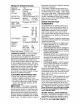
PRODUCT SPECIFICATIONS Gasoline Capacity and Type: 1.25 Unleaded and Regular Oil Type SAE 10W30 (above 32°F) SAE 5W-30(below API-SF-SJ): 32°F Oil Capacity: W/Filter: W/O Filter: Spark Plug: (Gap: .040") Champion RC12YC Forward: 1st 2nd 3rd 4th 5th 6th Ground Speed (MPH): 4.0 Pints 3.75 Pints Reverse: 1.2 1.5 2.4 3.5 4.8 5.3 1.5 Tire Pressure: Front: Rear: 14 PSI 10 PSI Charging System: 15 Amps @ 3600RPM Battery: AmpiHr: Min. CCA: Case Size: 28 230 U1R Blade Bolt Torque: 27-35 Ft.
Steering Wheel Steering Wheel Insert (1) Large Flat Washer (1) Locknut (1) Hex Bolt 1/4-28 x 1-1/4 1/2-20 @ (1) Locknut 1/4-28 Steering Extension Shaft Steering Wheel Adapter Seat @ i_(1) (1) Washer 17/32 x 1-3/16 x 12 Gauge Knob For Future Use Keys Slope Sheet Video (2) Keys "-t 7 Cassette
Your new tractor has been assembled at the factory with the exception of those parts left unassembled for shipping purposes. To ensure safe and proper operation of your tractor all parts and hardware you assemble must be tightened securely. Use the correct tools as necessary to insure proper tightness. Review the video cassette before you begin. TOOLS REQUIRED FOR ASSEMBLY A socket wrench set will make assembly easier. Standard wrench sizes you need are listed below.
5. Pivot seat and pan forwardand assembleadjustmentknob and flat washer loosely.Do not tighten. 6. Lower seat into operatingposition and sit in seat. 7. Slide seat until a comfortableposition is reachedwhich allowsyou to press clutch/brakepedal all the way down. 8. Get off seat withoutmoving its adjusted position. 9. Raise seat and tightenadjustment knobsecurely. NOTE: You may now roll or drive your tractor off the skid. Follow the appropriate instruction below to remove the tractor from the skid.
INSTALL MULCHER PLATE (If previously removed) 1. Raise and hold deflector shield in upright position. 2. Place front of mulcher plate over front of mower deck opening and slide into place, as shown. 3. Hook front latch into hole on front of mower deck. 4. Hook rear latch into hole on back of mower deck. Mulcher Plate Deflector Shielc POSITION OF See the figures that are shown for replacing motion and mower blade drive belts in the Service and Adjustments section of this manual.
These symbols may appear on your tractor or in literature supplied with the product. Learn and understand their meaning. R N H L REVERSE NEUTRAL HIGH LOW ENGINE OFF LIGHTS ON OVER TEMP FUEL ENGINE ON OIL PRESSURE I'.
KNOW YOUR TRACTOR READ THIS OWNER'S MANUAL AND SAFETY RULES BEFORE OPERATING YOUR TRACTOR Compare the illustrations with your tractor to familiarize yourself with the locations of various controls and adjustments. Save this manual for future reference. Ignition Switch Attachment Clutch Lever Ammeter ...... Light Switch Position Lift Lever Plunger --. ThrottletChoke Control Clutch/Brake PedaI Attachment Lift Lever Height ustment Indicator "- ......
The operation of any tractor can result in foreign objects thrown into the eyes, which can result in severe eye damage. Always wear safety glasses or eye shields while operating your tractor or performing any adjustments or repairs. We recommend a wide vision safety mask over spectacles or standard safety glasses. HOW TO USE YOURTRACTOR TO SET PARKING BRAKE Your tractor is equipped with an operator presence sensing switch.
• The average lawn should be cut to approximately 2-1/2 inches during the cool season and to over 3 inches during hot months. For healthier and better looking lawns, mow often and after moderate growth. • For best cutting performance, grass over 6 inches in height should be mowed twice. Make the first cut relatively high; the second to desired height. Attachment Clutch Lever "Engaged" Position Gauge Wheel o_% Mounting \ .
BEFORE STARTING THE ENGINE TO START CHECK ENGINE OIL LEVEL The engine in your tractor has been shipped, from the factory, already filled with summer weight oil. 1. Check engine oil with tractor on level ground. 2. Unthread and remove oil fill cap/ dipstick; wipe oil off. Reinsert the dipstick into the tube and rest oil fill cap on the tube. Do not thread the cap onto the tube. Remove and read oil level. If necessary, add oil until "FULl" mark on dipstick is reached. Do not overfill.
MOWING TIPS MULCHING MOWING TIPS IMPORTANT: For best performance, keep mower housing free of built-up grass and trash. Clean after each use. • The special mulching blade will recut the grass clippings many times and reduce them in size so that as they fall onto the lawn they will disperse into the grass and not be noticed. Also, the mulched grass will biodegrade quickly to provide nutrients for the lawn.
As Yoo CO PLETE FILL IN DATES REGULAR SERVICE _%q_FE_j_,_-_r_ SERVIC ....
TRACTOR IMPORTANT: To ensure proper assembly, center hole in blade must align with star on mandrel assembly. 4. Reassemble blade bolt, lock washer and flat washer in exact order as shown. 5. Tighten blade bolt securely (27-35 Ft. Lbs. torque). IMPORTANT: Blade bolt is heat treated. If bolt needs replacing, replace only with approve bolt shown in the Repair Parts. Always observe safety rules when performing any maintenance.
BATTERY Change the oil after every 50 hours of operation or at least once a year if the tractor is not used for 50 hours in one year. Check the crankcase oil level before start- Your tractor has a battery charging system which is sufficient for normal use. However, periodic charging of the battery with an automotive charger will extend its life. • Keep battery and terminals clean. • Keep battery bolts tight. • Keep small vent holes open. • Recharge at 6-10 amperes for 1 hour.
2. Remove wing nut and air cleaner from base. TO SERVICE PRE-CLEANER 3. Slide foam pre-cleaner off cartridge. 4. Wash it in liquid detergent and water. 5. Squeeze it dry in a clean cloth. Allow it to dry. 6. Saturate it in engine oil. Wrap it in clean, absorbent cloth and squeeze to remove excess oil. TO SERVICE CARTRIDGE 1. Replace a dirty, bent, or damaged cartridge. NOTE: Do not wash the paper cartridge or use pressurized air, as this will damage the cartridge. 2.
_IL WARNING: TO AVOID SERIOUS INJURY, BEFORE PERFORMING VICE OR ADJUSTMENTS: 1. 2. 3. 4. 5. 6. ANY SER- Depress clutch/brake pedal fully and set parking brake. Place gearshift lever Jn neutral (N) position. Place attachment clutch Jn "DISENGAGED" position. Turn ignition key to "STOP" and remove key. Make sure the blades and all moving parts have completely stopped. Disconnect spark plug wire from spark plug and place wire where it cannot come in contact with plug.
7. Push clutch cable housing guide into bracket, slide collar onto guide and secure with large retainer spring. 8. Place flat washer and clutch spring on idler pulley bolt and secure with small retainer spring. 9. Install belt onto engine pulley. Check adjustment on right side of tractor. Measure distance "D" directly in front and behind the mandrel at bottom edge of mower housing as shown. • Before making any necessary adjustments, check that both front links are equal in length.
TO REPLACE BELT MOWER BLADE TO ADJUST BRAKE DRIVE 1. Depress clutch/brake pedal all the way down and engage parking brake. 2. Measure distance between brake operating arm and nut 'W' on brake rod. 3. If distance is other than 1-1/2", loosen jam nut and turn nut 'W' until distance becomes 1-1/2". Retighten jam nut against nut "A". 4. Road test tractor for proper stopping distance as stated above. Readjust if necessary.
3. Pull belt toward front of tractor and roll around the top groove of engine pulley. 4. Install belt through stationary idler and clutching idler. 5. Make sure belt is in all pulley grooves and inside all belt guides and keepers. 6. Install mower (See "TO INSTALL MOWER" in this section of manual). FRONT WHEEL TOE-INtCAMBER The front wheel toe-in and camber are not adjustable on your tractor.
TO ATTACH JUMPER CABLES 1. Connect one end of the RED cable to the POSITIVE (+) terminal of each battery(A-B), taking care not to short against tractor chassis. 2. Connect one end of the BLACK cable to the NEGATIVE (-) terminal (C) of fully charged battery. 3. Connect the other end of the BLACK cable (D) to good chassis ground, away from fuel tank and battery. TO REMOVE CABLES, REVERSE ORDER 1. BLACK cable first from chassis and then from the fully charged battery. 2. RED cable last from both batteries.
ENGINE 2. Start engine and allow to warm for five minutes. Make adjustments with engine running and shift/motion control lever in neutral (N) position. 3. Idle speed setting - With throttle control lever in slow position, engine should idle at 1750 RPM. If engine idles too slow or fast, turn idle speed adjusting screw in or out until correct idle is attained. 4.
Immediately prepare your tractor for storage at the end of the season or if the tractor will not be used for 30 days or more. _WARNING: Never store the tractor with gasoline in the tank inside a building where fumes may reach an open flame or spark. Allow the engine to cool before storing in any enclosure. blended fuels (called gasohol or using ethanol or methanol) can attract moisture which leads to separation and formation of acids during storage.
TROUBLESHOOTING CHART See appropriate section in manual unless directed to Sears service center PROBLEM Will not start CAUSE CORRECTION 1. Out of fuel. 2. Engine not "CHOKED" properly. 3. Engine flooded. 4. 5. 6. 7 Bad spark plug. Dirty air filter. Dirty fuel filter. Water in fuel. 8. Loose or damaged wiring. 9. Carburetor out of adjustment. 10. Engine valves out of adjustment, Hard to start 1. Dirty air filter. 2. Bad spark plug. 3. Weak or dead battery. 4. Dirty fuel filter. 5.
TROUBLESHOOTING CHART See appropriate section in manual unless directed to Sears service center PROBLEM Loss of power CAUSE CORRECTION 1. Cutting too much grass/too fast. 2. Throttle in "CHOKE" position. 3. Build-up of grass, leaves and trash under mower. 4. Dirty air filter. 5. Low oil level/dirty oil. 6. Faulty spark plug. 7. Dirty fuel filter. 8. Stale or dirty fuel. 9. Water in fuel. 10. Spark plug wire loose. 11. 12. 13. 14. Dirty engine air screen/fins. Dirty/clogged muffler.
TROUBLESHOOTING See appropriate CHART section in manual unless directed to Sears service center PROBLEM Mower blades will not rotate Poor grass discharge CAUSE CORRECTION 1. Obstruction in clutch mechanism. 2. Worn/damaged mower drive belt. 3. Frozen idler pulley. 4. Frozen blade mandrel. 1. Remove obstruction. 2. Replace mower drive belt. 3. Replace idler pulley. 4. Replace blade mandrel. 1. Engine speed too slow. 2. 3. Travel speed Wet grass. too fast. 4. Mower deck not level. 5.
TRACTOR- - MODEL NUMBER 917.273130 SCHEMATIC BATTERY FUSE STARTER BL_OK I FUEL I i LINE I I i I I I I FUEL SHUT-OFF SOLENOll3 iI _0 EQU[_PEL_ L SEAT SWITCH (NOT OCCUPIED) I 8?" _ 88 i OPERATOF_ BLA_ PLUG SPARK GAP (2 PLUGS ON q_lN CYL.
TRACTOR- - MODEL NUMBER 917.
TRACTOR- - MODEL NUMBER 917.
TRACTORCHASSIS AND ENCLOSURES - MODEL NUMBER 917.
TRACTORCHASSIS AND ENCLOSURES - MODEL NUMBER 917.
TRACTOR- - MODEL NUMBER 917.
TRACTOR- - MODEL NUMBER 917.
TRACTORSTEERING ASSEMBLY - MODEL NUMBER 917.
TRACTORSTEERING ASSEMBLY KEY NO, I 2 3 4 5 8 8 I0 II I2 I3 I5 I7 28 28 29 30 32 38 37 38 39 40 4I 42 43 44 48 5I 54 85 87 88 7I 82 87 88 9I - MODEL NUMBER 917.
TRACTOR- - MODEL NUMBER 917.
TRACTOR- - MODEL NUMBER 917.
TRACTOR- - MODEL NUMBER 917.
TRACTOR - - MODEL NUMBER 917.273130 DECALS 16 2 13 6 3 I3 10 II 1I 20 9 ,I6 I5 12 KEY PART NO, NO, DESCRIPTION KEY NO, PART NO, DESCRIPTION 1 2 3 4 5 6 7 8 9 10 11 12 Decal, Decal, Decal, Decal, Decal, Decal, Decal, Decal, Decal, Decal, Decal, Decal, 13 14 15 16 17 18 20 ------ 177353 I60396 179128 184842 I84643 164065 149516 I38311 I65600X428 I65799X426 I84989 184990 Decal Dash Panel Decal V-Belt Schematic Decal Deck B 42 Decal Grille RH Decal Grille LH Decal Strg.
TRACTOR - - MODEL NUMBER 917.
TRACTOR- - MODEL NUMBER 917.273130 LIFT ASSEMBLY KEY NO, PART NO, DESCRIPTION I 2 3 4 5 6 7 8 11 I2 I3 I5 I6 17 I8 I9 20 31 32 I59460 I59471 105767X 12000002 19211621 I20183X I25631X I22365X I39865 139866 STD624008 173288 73350800 175689 73800800 139868 163552 I69865 73540600 Washer Asm Inner Spring W/Plunger Shaft Asm. Lift Pin Groove E Ring #5133-62 Washer 21/32 × 1 ;(2I Ga. Bearing Nylong Grip Handle Fluted Button Plunger Read Link Asm Lilt L.H. Link Asm Lilt R.H.
TRACTOR- - MODEL NUMBER 917.273130 MOWER DECK 106/_ 113 102 193 105 111 114 118 _ 119 F _117 21 23 24 25 \ 16 29 .18 18 5 6 10 ...-.
TRACTOR- - MODEL NUMBER 917.273130 MOWER DECK KEY NO, PART NO, 1 2 3 4 5 6 8 9 10 165892 STD533107 138017 165460 STD824008 178024 850857 STD55II37 140298 1I 13 14 15 18 18 19 20 2I 23 24 25 28 27 28 29 30 3I 32 33 34 38 37 40 44 45 48 48 52 53 54 55 56 DESCRIPTION Mower Deck Assembly, 42' Bolt Bracket Assembly, Sway Bar, Front Bracket Sway Bar 38/42" Deck Retainer Spring Bar Sway Deck Bolt, Hex 3/8-24 x 1.25 Gr.
TRACTOR- MODEL NUMBER 917.273130 PEERLESS TRANSAXLE - - MODEL NUMBER 206-545C KEY NO. 157 35 .
TRACTOR- MODEL NUMBER 917.273130 PEERLESS TRANSAXLE - - MODEL NUMBER 206-545C PART NO.
TRACTOR- MODEL NUMBER 917.
TRACTOR- MODEL NUMBER 917.273130 KOHLER ENGINE-MODEL NUMBER CV490, TYPE NUMBER 27508 CYLINDER H EADNALVFJBREATH KEY NO, PART NO, 1 2 25_351-01S Liften valve (2) 12_755-94_S Kit, cylinder head (Includes 3417, Gaskets 12 041 014S (Qty. 2), 12 041 02-8, & 12 041 0348) 12_411-03_S Rod, push (2) 12_041410S Gasket, cylinder head 12_017401S Valve, intake (Std.) 12_017402S Valve, intake (.25) 12_016-01 S Valve. exhaust (Std.) 12-016-02 S Valve, exhaust (.25) 25q 39-60-S Plug, allen hd.
TRACTOR - - MODEL NUMBER 917.
TRACTOR- MODEL NUMBER 917.273130 KOHLER ENGINE-MODEL NUMBER CV490,TYPE NUMBER 27508 IGNITION_ELECTRICAL KEY NO, PART NO, 1 12_086-14_S Screw, hex. flange M10x1.5×46 12_468-03 S Washer, plain 3/8" 24q62-03 S Screen, grass 25_086-47_S Bolt, shoulder M6x1.0x16 (4) 12 157-06 S Fan X42_15-S Key 12_025-15 S Flywheel 12 155-09_S Connector M-548025-S Screw. hex. cap M5xO.Sx25 (2) 12-065-09_S Stator -15 amp with stator brake M-545020-S Screw. hex. flange M5x0.
TRACTOR- MODEL NUMBER 917.273130 KOHLER ENGINE-MODEL NUMBER CV490, TYPE NUMBER 27508 STARTING SYSTEM I ENGINE CONTROLSJ ! L 17 0 ! I 11 OIL PAN / LUBRICATION _....
TRACTOR - - MODEL NUMBER 917.273130 KOHLER ENGINE-MODEL NUMBER CV490, TYPE NUMBER 27508 STARTING SYSTEM ENGINE CONTROLS KEY NO, PART NO, KEY NO, PART NO, 2 3 4 5 6 7 8 M-839070-S Screw, hex. flange Mgx1.25x79 (2) 25-098-07 S Starter assembly (Includes 3-8) 12-755-54-S Kit, drive end 12-227-18-S Cap, drive end 12-179-05 S Armature 12-221-01-S Kit, brush & spring 12-227-13 S Cap, commutator end 12-211-01-S Bolt, he×.
TRACTOR- MODEL NUMBER 917.
TRACTOR- MODEL NUMBER 917.273130 KOHLER ENGINE-MODEL NUMBER CV490, TYPE NUMBER 27508 CRANKSHAFT FUEL SYSTEM KEY PART NO, NO, 1 2 3 4 5 6 7 8 9 10 11 DESCRIPTION M-641060-S Nut, hex. flange M6x1.0 (2) M-629116S Stud M6x1.0x116 (2) 12-853-118-S Kit, carburetor wtgaeket (Includes 4,5,6 qty 1 Tie, cable 12-454-03-S.
SUGGESTED GUIDE FOR SIGHTING SLOPES FOR SAFE OPERATION _o 1. Fold this page along dotted line indicated above. 2. Hold page before you so that its left edge is vertically parallel to a tree trunk or other upright structure. 3. Sight across the fold in the direction of hill slope you want to measure. 4. Compare the angle of the fold with the slope of the hill.
Get it fixed, at your home or ours! Your Home For repair - in your home - of all major brand apphances, lawn and garden equipment, or heating and coohng systems, no matter who made it, no matter who sold itt For the replacement parts, accessories and owner's manuals that you need to do-it-yourself. For Sears professional _nstallahon of home apphances and items hke garage door openers and water heaters. 1-800-4-MY-HOME (1-800-469-4663) www.sears.com ® Anytime, day or night (U S A and Canada) www.sears.