Owner's Manual CRRFT.TMRN ° LAWN TRACTOR 24.0 HP, 48" Mower Electric Start Automatic Transmission Model No. 917.273620 r_ from previouslyhas built the engine, read This product a lowengines. emission Before engine you whichstart operates differently and understand this Owner's Manual.
Warranty................................................ 2 SafetyRules .......................................... 3 ProductSpecifications ..........................6 Assembly/Pre-Operation.......................7 Operation............................................... 9 MaintenanceSchedule........................15 Maintenance........................................15 Serviceand Adjustments.....................19 Storage................................................ 27 Troubleshooting...................
IMPORTANT: This cutting machine is capable of amputating hands and feet and throwing objects. Failure to observe the following safety instructions could result in serious injury or death. WARNING: In order to prevent • accidental starting when setting up, transporting, adjusting or making repairs, always disconnect spark plug wire and place wire where it cannot contact spark plug. WARNING: hill in neutral, tractor.
II. SLOPE OPERATION • Slopes are a major factor related to loss of control and tip-over accidents, which can result in severe injury or death. Operation on all slopes requires extra caution. If you cannot back up the slope or if you feel uneasy on it, do not mow it. • Mow up and down slopes, not across. • Watch for holes, ruts, bumps, rocks, or other hidden objects. Uneven terrain could overturn the machine. Tall grass can hide obstacles.
• • • • Removegas-poweredequipmentfrom the truckor trailerand refuelit on the ground.If this is not possible,then refuelsuch equipmentwith a portable container,ratherthan from a gasoline dispensernozzle. Keepthe nozzle in contact with the rim of the fuel tank or containeropeningat all times untilfueling is complete.Do not use a nozzle lock-opendevice. If fuel is spilledon clothing, change clothingimmediately. Neveroverfill fuel tank.Replacegas cap and tighten securely.
PRODUCT In the state of California SPECIFICATIONS Gasoline Capacity and Type: 4 Gallons Unleaded Regular Oil Type 'API-SG-SL): SAE 30 (above SAE 5W-30 (below 32°F) Oil Capacity: W/Filter: 4.0 Pints W/O Filter: 3.75 Pints Spark (Gap: Champion Plug: .040") Ground (MPH): Speed Tire Pressure: Charging Battery: Blade System:16 32°F) QC12YC Forward: Reverse: 00- Front: Rear: 14 PSI 10 PSI Amps @ 3600 RPM Amp/Hr: Min. CCA: Case size: Bolt Torque:45-55 5.5 2.4 35 280 U1R Ft. Lbs.
Keys (2) Keys Video Cassette Slope Sheet Bubble Level Mower Leveling Wrench Your new tractor you begin. (1) Oil Drain Tube For Future Use has been assembled at the factory. When right or left hand is mentioned in this manual, it means, from your point of view, when you are in the operating position (seated behind the steering wheel). TO REMOVE TRACTOR CARTON UNPACK CARTON FROM 1. Cut along dotted lines on all four panels of carton. Remove end panels and lay side panels flat. 2.
TO DRIVE CHECK Operation After you learn how to operate your tractor, check to see that the brake is properly adjusted. See "TO ADJUST BRAKE" in the Service and Adjustments section of this manual. TRACTOR OFF SKID (See section for location and function of controls) _WARNING: Before starting, read, understand and follow all instructions in the Operation section of this manual. Be sure tractor is in a well-ventilated area. Be sure the area in front of tractor is clear of other people and objects. 1.
These symbols may appearon your tractoror in literaturesupplied with the product. Learn and understandtheir meaning.
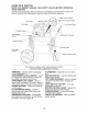
KNOW YOUR TRACTOR READ THIS OWNER'S MANUAL AND SAFETY YOUR TRACTOR RULES BEFORE OPERATING Compare the illustrations with your tractor to familiarize yourself with the locations of various controls and adjustments. Save this manual for future reference.
SAFETYGLASSES The operation of any tractor can result in foreign objects thrown into the eyes, which can result in severe eye damage. Always wear safety glasses or eye shields while operating your tractor or performing any adjustments or repairs. We recommend standard safety glasses or a wide vision safety mask worn over spectacles. HOW TO USE YOUR TRACTOR NOTE: TO SET PARKING tractor is standing idle with the engine running, hot engine exhaust gases may cause "browning" of grass.
TO ADJUST GAUGE WHEELS TO OPERATE Gauge wheels are properly adjusted when they are slightly off the ground when mower is at the desired cutting height in operating position. Gauge wheels then keep the deck in proper position to help prevent scalping in most terrain conditions. NOTE: Be sure tractor is on a flat level surface. 1. Lower mower and adjust mower to desired cutting height. 2. Remove retainer spring and clevis pin which secure each gauge wheel bar. 3. Lower gauge wheels to ground.
BEFORE CHECK STARTING ENGINE THE ENGINE 2. Sit on seat in operating position, depress clutch/brake pedal and set parking brake. 3. Place motion control lever in neutral (N) position. 4. Move attachment clutch to disengaged position. 5. Move throttle control to fast position 6. Pull choke control out for a cold engine start attempt. For a warm engine start attempt the choke control may not be needed. NOTE: Before starting, read the warm and cold starting procedures below. 7.
3. Allow one minute for transmission to warm up. This can be done during the engine warm up period. • The attachments can be used during the engine warm-up period after the transmission has been warmed up and may require the choke control be pulled out slightly. NOTE: If at a high altitude (above 3000 feet) or in cold temperatures (below 32 F) the carburetor fuel mixture may need to be adjusted for best engine performance (see "TO ADJUST CARBURETOR" in the Service and Adjustments section of this manual).
FILL IN DATES AS YOU C 0 M PLETE J__/,"_ REGULAR SERVICE Check Check _.
TRACTOR Always observe safety rules when forming any maintenance. BRAKE OPERATION NOTE: Protect your hands with gloves and/or wrap blade with heavy cloth. 2. Remove blade bolt by turning counterclockwise. per- 3. Install new or resharpened blade with stamped "THIS SIDE UP" facing deck and mandrel assembly. IMPORTANT: To ensure proper assembly, center hole in blade must align with star on mandrel assembly. 4. Install and tighten blade bolt securely (45-55 Ft. Lbs. torque).
ENGINE ever, periodic charging of the battery with an automotive charger will extend its life. • Keep battery and terminals clean. • Keep battery bolts tight. • Keep small vent holes open. • Recharge at 6-10 amperes for 1 hour. NOTE: The original equipment battery on your tractor is maintenance free. Do not attempt to open or remove caps or covers. Adding or checking level of electrolyte is not necessary.
7. Refill enginewith oil through oil fill dipstick tube. Pour slowly. Do not overfill. For approximatecapacitysee "PRODUCT SPECIFICATIONS"section of this manual. 8. Use gauge on oil fill cap/dipstickfor checkinglevel. For accuratereading, tighten dipstickcap securely onto the tube beforeremovingdipstick. Keepoil at "FULl" line on dipstick.Tightencap onto the tube securelywhen finished.
CLEANING We do not recommend using a garden hose or pressure washer to clean your tractor unless the engine and transmission are covered to keep water out. Water in engine or transmission will shorten the useful life of your tractor. Use compressed air or a leaf blower to remove grass, leaves and trash from tractor and mower. • Clean engine, battery, seat, finish, etc. of all foreign matter. • Keep finished surfaces and wheels free of all gasoline, oil, etc.
2. Slide mower under tractor with deflec- • Using the lift lever, place mower in position where no part of the mower, including gauge wheels, is touching the ground. • From left side of tractor, find the level decal on top of mower and place bubble level on decal as indicated. • Mower is level side-to-side when bubble is between the two lines in the bubble level. tor shield to right side of tractor. IMPORTANT: Check belt for proper routing in all mower pulley grooves. 3.
BOTH FRONT PLATE LINKS MUST BE EQUAL IN LENGTH Suspension Arm Lift Link Adjustment Nut FRONT-TO-BACK ADJUSTMENT IMPORTANT: Deck must be level sideto-side. If the following front-to-back adjustment is necessary, be sure to adjust both front links equally so mower will stay level side-to-side. To obtain the best cutting results, the mower blades should be adjusted so the front tip is approximately 1/8" to 1/2" lower than the rear tip when the mower is in its ,_bghest position. CAUTION: Blades are sharp.
18.Engagebelt tension rod by pushing rod into locking bracket. I R.H. Mandrel Cover Belt Tension Rod (Disengaged Position) Clutch Pulley Idler Pulleys Mandrel Spring Arm R.H. Sus Primary Idler Arm TO REPLACE MOWER (SECONDARY) DRIVE Park the tractor on parking brake. 1. Remove mower MOWER" in this 2. Remove screws mandrel covers REMOVE MOWER BLADE 9. Remove any dirt or grass which may have accumulated around mandrels and entire upper deck surface. 10.
17. Reinstall INSTALL mower to tractor (See "TO MOWER" in this section of manual). Secondary Idler Arm L.H. Mandrel Idler Pulley Sp ling Secondary Spring Arm Center Mandrel Mower Blade (Secondary) Drive Belt TO CHECK AND ADJUST BRAKE . Your tractor is equipped with an adjustable brake system which is mounted on the right side of the transaxle.
TO REPLACE MOTION DRIVE BELT TRANSMISSION REPLACEMENT Park the tractor on level surface. Engage parking brake. For assistance, there is a belt installation guide decal on bottom side of left footrest. BELT REMOVAL Should your transmission require removal for service or replacement, it should be purged after reinstallation and before operating the tractor. See "PURGE TRANSMISSION" in the Operation section of this manual. - 1. Remove mower (See "TO REMOVE MOWER" in this section of manual).
If your battery is too weak to start the engine, it should be recharged. (See "BATTERY" in the Maintenance section of this manual). If "jumper cables" are used for emergency starting, follow this procedure: IMPORTANT: Your tractor is equipped with a 12 volt system. The other vehicle must also be a 12 volt system. Do not use your tractor battery to start other vehicles. TO ATTACH 1. 2. 3. JUMPER 2. 7. 8. 9. - CABLES, t_::"_ TO REPLACE 1. 2.
TO ADJUST CARBURETOR Your carburetor is not adjustable. If your engine does not operate properly due to suspected carburetor problems, take your tractor to a Sears or other qualified service center for repair and/or adjustment. High speed stop is factory adjusted. Do not adjust - damage may result. IMPORTANT: Never tamper with the engine governor, which is factory set for proper engine speed. Overspeeding the engine above the factory high speed setting can be dangerous.
Immediately prepare your tractor for storage at the end of the season or if the tractor will not be used for 30 days or more. _IkWARNING: Never store the tractor with gasoline in the tank inside a building where fumes may reach an open flame or spark. Allow the engine to cool before storing in any enclosure. blended fuels (called gasohol or using ethanol or methanol) can attract moisture which leads to separation and formation of acids during storage.
TROUBLESHOOTING CHART: See appropriate section in manual unless directed to Sears service center PROBLEM Will not start Hard to start CAUSE 1. Out of fuel. 2. Engine not "CHOKED" properly. 3. Engine flooded. 1. 2. 4. 5. 6. 7. Bad spark plug. Dirty air filter. Dirty fuel filter. Water in fuel. 4. 5. 6. 7. 8. 9. Loose or damaged wiring. Carburetor out of adjustment. 8. 9. 3. 10. Engine valves out of adjustment. 10. 1. Dirty air filter. 2. Bad spark plug. 3. Weak or dead battery. 4.
TROUBLESHOOTING CHART: See appropriate section in manual unless directed to Sears service center PROBLEM Loss of power (continued) CAUSE CORRECTION 6. Faulty spark plug. 6. 7. 8. Dirty fuel filter. Stale or dirty fuel. 7. 8. 9. Water in fuel. 9. 10. Spark plug wire loose. 10. 11. 12. 13. 14. 11. 12. 13. 14. Dirty engine air screen/fins. Dirty/clogged muffler. Loose or damaged wiring. Carburetor out of adjustment. 15.
TROUBLESHOOTING CHART: See appropriate section in manual unless directed to Sears service center PROBLEM Poor grass discharge (continued) CAUSE CORRECTION 3. Wet grass. 3. 4. 5. Mower deck not level. Low/uneven tire air pressure. 4. 5. 6. Worn, 6. . 8. 9. bent or loose blade. Buildup of grass, leaves and trash under mower. Mower drive belt worn. Blades improperly 10. Improper blades installed. used. 11.
TRACTOR - - MODEL NUMBER 917,273620 SCHEMATIC BATTERY RED I FUSE AMMETER (OPTIONAL) STARTER BLACK I WHITE I I _ II _ SOLENOID [ J CLUTCH / BRAKE (PEDAL UP) ' I I ;EATS (NOT OCCIIPIFF)/ r I /\ FUEL, //\\ LINE ' I " ' , I ' LBLU E II-'--/ _ OPERATOR PRESENCE RELAY #1 U --_ %_-- _-I FUEL SHUT-OFF SOLENOID (IF SO EQUIPPED) _ _ /_/._GGAL]_'_ 'X I X (OPTIONAL) _ /////:i_,A,_ IGNITION REMOVABLE CONNECTIONS 16 AMP _ • DC @ 3600 RPM (REGULATOR _ .
TRACTOR - - MODEL NUMBER 917.273620 ELECTRICAL 22 / / 24._.
TRACTOR - - MODEL NUMBER 917.273620 ELECTRICAL KEY PART NO. NO.
TRACTOR - - MODEL CHASSIS AND ENCLOSURES NUMBER 917,273620 6 9O 166 54 58 54 158 1 209 21)9 6O 209 "_¢_166 209 74 209 chassis-stealth,stlt 38 16 209 34
TRACTOR - - MODEL CHASSIS AND ENCLOSURES NUMBER 917,273620 KEY PART NO. NO.
TRACTOR - - MODEL NUMBER 917,273620 GROUND DRIVE 23 212 I 1202 150 \ lO 165 156 151 166 51 32 36 37 2 16 I 53 30 55 16 x_ 84 16 77 / 24 .
TRACTOR - - MODEL NUMBER 917.273620 GROUND DRIVE KEY NO. 1 PART NO. --- DESCRIPTION KEY NO. PART NO. 63 65 66 71 73 74 174607 10040700 154778 169183 169182 137057 8 9 10 165866 179334 76020416 Transaxle, HydroGear, Model Number 314-0510 (See Break down) Rod Shift Fend. Clutch Electric Pin Cotter 1/8 x 1 14 15 16 17 19 20 21 10040400 74490544 73800500 126197X 73800600 173937 140845 Washer Lock Hvy 1/4 Bolt Hex FIghd 5/16-18 Gr. 5 Nut Lock Hex W/Ins. 5116-18 unc Washer 1-1/20D x 15132 ID x.
TRACTOR STEERING ASSEMBLY r/ t l/ _ l _ i_ sI - - MODEL NUMBER 917,273620 1 J 67 68 67 J J 46 29 13 65 46 6 J 68 32 J 11 // 15 40 steering 38 stealth prem 10
TRACTOR STEERING ASSEMBLY - - MODEL NUMBER 917.273620 KEY NO. PART NO. DESCRIPTION 1 2 159944X428 184706 Wheel Steering Axle Asm 3 4 5 6 169840 169839 6266H 121748X Spindle Asm LH Spindle Asm RH Bearing Race Thrust Harden Washer 25132 x 1-5/8 x 16 Ga. 8 10 11 12 13 15 17 29 32 12000029 175121 10040600 73940800 136518 145212 177883 17000612 180580 Ring Klip #t5304-75 Link Drag Washer Lock Hlcl Spr 3/8 Nut Hex Jam Toplock 1/2-20 Spacer Bearing Axle Front Nut Hex Flange Lock Shaft Asm.
TRACTOR - - MODEL NUMBER 917,273620 ENGINE 2 1 13 , 32 17_------___ I I i 33 ,,_%--- 33 23 29 I OPTIONAL EQUIPMENT Spark Arrester I engine=bs intek=twin 39 40 17
TRACTOR - - MODEL NUMBER 917,273620 ENGINE KEY NO. PART NO.
TRACTOR - - MODEL NUMBER 917,273620 SEAT ASSEMBLY 1 10 / 24 i I I 5 I I I iC i I 25 11 17 seat Itknob 12 2 KEY PART NO. NO. 1 2 3 4 5 6 7 8 9 10 11 12 180598 180166 STD523710 19131610 145006 STD541437 124181X 17000616 19131614 180186 166369 121246X DESCRIPTION Seat Bracket Pivot Seat Bolt Fin Hex 318-16 unc x 1 Washer 13/32 x 1 x 10 Ga Clip Push-in Nut Hex w/Ins. 3/8-16 unc Spring Seat Cprsn Screw 3t8-16 x 1-1/2 Washer 13/32 x 1 x 14 Ga. Pan Seat Knob Seat Adj.
TRACTOR - - MODEL NUMBER 917,273620 DECALS 7 11 5 16 9 \ 3 13 21 21 10 2O 6 15 12 1 26 KEY NO. PART NO. DESCRIPTION KEY NO. PART NO.
TRACTOR - - MODEL NUMBER 917,273620 LIFT ASSEMBLY 41 5 37 38 40 3 2 6 5 44
TRACTOR - - MODEL NUMBER 917.273620 LIFT ASSEMBLY KEY PART NO. NO. DESCRIPTION 1 2 3 4 5 179504 159476 138284 12000002 19211621 Plunger Assembly Shaft Assembly, Lift Pin, Groove E-Ring Washer 21/32 x 1 x 21 Ga. 6 7 11 12 13 15 16 17 18 20 31 32 120183X 175830 175370 175371 4939M 175562 73350800 175689 73800800 163552 176205 175994 Bearing, Nylon Grip, Handle, Fluted Link, Lift, LH. Link, Lift, R.H. Retainer Spring Plate Asm Suspension Front Nut Hex Jam 1/2-13 uric Trunnion Front Susp.
TRACTOR - - MODEL NUMBER 917,273620 MOWER DECK 46 33 112 43 121 114 21 47 \ 122_ 21 116 18 mower 46 deck.
TRACTOR - - MODEL NUMBER 917,273620 MOWER DECK KEY PART KEY PART NO. NO. DESCRIPTION NO. NO. DESCRIPTION 1 3 5 6 8 180358 138017 4939M 178024 174365 173921 52 54 55 56 57 72 91 92 94 95 97 98 175820 74780616 72140608 155986 156941 19131312 180535 73800600 176066 180534 178515 179479 Pulley Idler Flat Bolt Fin Hex 3/8-16 11 Deck Weldment Mower 48 Bracket Asm., Sway Bar Retainer Spring Bar Sway Deck Bolt 7/16 Asm.
.-r 13 0 Q rll _128 88 ;g --I _,-.I z_ r--.t mO , ZI ! ! 109 o_ _0 m i 84_. 31 (3O / 81 83 79 73 r-_ z m cr- _z wl.- m_ _w _m 19 _57 2_ 900 _127 6_ €.n .
TRACTOR - - MODEL NUMBER 917.273620 HYDRO GEAR TRANSAXLE - - MODEL NUMBER 314-0510 KEY NO. PART NO.
TRACTOR - - MODEL NUMBER 917.
TRACTOR - - MODEL NUMBER 917.273620 BRIGGS ENGINE-MODEL NUMBER 445777 TYPE NUMBER 0168-E1 D 883_ 35_ 36 1029 1022 1100 _ 798 _ 33Y21'2o,° \ _°387_-_'_&628 =_ I _o_ 914_ 21_ 914 918_ 12_ 163_ 121 CARBURETOR 616U 1370 51 _ 1_1128 o__1 1123© 1124_ 276 @ _ | 104 '_ 105_ __-_-__ 552 @ 552A8 1_o_ 633@ 987_ 977 CARBURETOR 51 198111128| _1 1'__1, _1 16_1_11 15°[_1 108_1 _1 b_130 95.
TRACTOR - - MODEL NUMBER 917.
TRACTOR - - MODEL NUMBER 917.273620 BRIGGS ENGINE-MODEL NUMBER 445777 TYPE NUMBER 0168-E1 KEY NO. PART NO.
TRACTOR - - MODEL NUMBER 917.273620 BRIGGS ENGINE-MODEL NUMBER 445777 TYPE NUMBER 0168-E1 KEY NO. PART NO.
Your Home For repair - in your home - of all major brand appliances, lawn and garden equipment, or heating and cooling systems, no matter who made it, no matter who sold it! iiiiiiiiiiiiiiii_ iiiiiiiiiiiiiiii_ iiiiiiiiiiiiiiii_ iiiiiiiiiiiiiiii_ iiiiiiiiiiiiiiii_ iiiiiiiiiiiiiiii_ iiiiiiiiiiiiiiii_ iiiiiiiiiiiiiiii_ iiiiiiiiiiiiiiii_ iiiiiiiiiiiiiiii_ iiiiiiiiiiiiiiii_ iiiiiiiiiiiiiiii_ iiiiiiiiiiiiiiii_ iiiiiiiiiiiiiiii_ iiiiiiiiiiiiiiii_ iiiiiiiiiiiiiiii_ iiiiiiiiiiiiiiii_ iiiiiiiiiiiiiiii_ iiiiiiiiiiiii