Owner's Manual CRRFTSMRN° j_]l I, GARDEN TRACTOR 25.0 HE 48" Mower Electric Start Automatic Transmission Model No. 917.276360 [_ This product has a low emission engine which operates differently from previously built engines. Before you start the engine, read and understand this Owner's Manual. IMPORTANT: Read and follow all Safety Rules and Instructions before operating this equipment.
Warranty................................................ 2 SafetyRules .......................................... 3 ProductSpecifications...........................6 Assembly/Pre-Operation.......................7 Operation............................................... 9 MaintenanceSchedule........................16 Maintenance........................................16 Service andAdjustments.....................21 Storage................................................ 29 Troubleshooting...................
IMPORTANT:This cutting machineis capable of amputatinghands and feet and throwing objects.Failureto observethe followingsafety instructionscould resultin serious injury or death. WARNING: In order to preventaccidental starting when setting up, transporting,adjustingor making repairs, alwaysdisconnectspark plug wire and place wire where it cannotcontact spark plug. WARNING: Do not coast down a hill in neutral,you may losecontrol of the tractor.
I1. SLOPE OPERATION • Slopes are a major factor related to loss of control and tip-over accidents, which can result in severe injury or death. Operation on all slopes requires extra caution. If you cannot back up the slope or if you feel uneasy on it, do not mow it. • Mow up and down slopes, not across. • Watch for holes, ruts, bumps, rocks, or other hidden objects. Uneven terrain could overturn the machine. Tall grass can hide obstacles.
• • • • Removegas-poweredequipmentfrom the truck or trailer and refuel it on the ground. If this is not possible,then refuelsuch equipment with a portable container, rather than from a gasoline dispenser nozzle. Keep the nozzle in contact with the rim of the fuel tank or container opening at all times until fueling is complete. Do not use a nozzle lock-open device. If fuel is spilled on clothing, change clothing immediately. Never overfill fuel tank. Replace gas cap and tighten securely.
PRODUCT SPECIFICATIONS In the state of California the above is re- Gasoline 5.0 Gallons Capacity and Type: Unleaded Regular Oil Type 'API-SG-SL): SAE 10W30 (above 32°F) SAE 5W-30 quired by law (Section 4442 of the California Public Resources Code). Other states may have similar laws. Federal laws apply on federal lands. A spark arrester for the muffler is available through your nearest Sears service center (See REPAIR PARTS section of this manual).
Keys Slope Sheet (1) Oil Drain Tube (2) Keys Your new tractor has been assembled at the factory. ADJUST When right or left hand is mentioned in this manual, it means, from your point of view, when you are in the operating position (seated behind the steering wheel). TO REMOVE TRACTOR FROM SEAT 1. Raise seat and loosen knobs. adjustment 2. Lower seat into operating sit in seat. position and 3.
TO DRIVE TRACTOR OFF (See SKID Operation section for location _nction of controls) and WARNING: Before starting, read, understand and follow all instructions in the Operation section of this manual. Be sure tractor is in a well-ventilated area. Be sure the area in front of tractor is clear of other people and objects. 1. Be sure all the above assembly steps have been completed. 2. Check engine oil level and fill fuel tank with gasoline. 3. Place freewheel control in "trans- 4. 5.
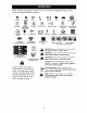
These symbols may appearon your tractor or in literature suppliedwith the product. Learn and understandtheir meaning.
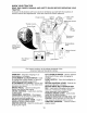
KNOW YOUR TRACTOR READ THIS OWNER'S TRACTOR MANUAL AND SAFETY RULES BEFORE OPERATING YOUR Compare the illustrations with your tractor to familiarize yourself with the locations various controls and adjustments. Save this manual for future reference.
SAFETYGLASSES The operation of any tractor can result in foreign objects thrown into the eyes, which can result in severe eye damage. Always wear safety glasses or eye shields while operating your tractor or performing any adjustments or repairs. We recommend standard safety glasses or a wide vision safety mask worn over spectacles. HOW TO USE YOUR TRACTOR TO SET PARKING • Never use choke to stop engine.
The cutting height range is approximately 1-1/2" to 4-1/2". The heights are measuredfrom the ground to the bladetip with the engine not running. These heightsare approximateand may vary dependingupon soil conditions, height of grassand types of grassbeing mowed. • The averagelawn should be cut to approximately2-1/2 inchesduring the cool season and to over 3 inchesduring hot months. For healthierand better lookinglawns, mowoften and after moderategrowth.
USING THE SYSTEM 1. 2. 3. 4. 5. REVERSE OPERATION Transmission Engaged Move motion control lever to neutral (N) position. With engine running, turn ignition key counterclockwise to ROS "ON" position. Look down and behind before backing. Slowly move motion control lever to reverse (R) position to start movement. When use of the ROS is no longer needed, turn the ignition key clockwise to engine "ON" position.
_,CAUTION: Wipe off any spilled oil or fuel. Do not store,spill or use gasoline near an open flame. IMPORTANT:When operatingin temperatures below32°F(0°C),use fresh,clean winter grade gasoline to help insure good cold weather starting. CAUTION: Alcohol blendedfuels (called gasoholor using ethanol or methanol)can attractmoisturewhich leads to separation and formationof acids duringstorage. Acidic gas can damagethe fuel system of an enginewhile in storage.
PURGE TRANSMISSION ,_CAUTION: Never engage MOWING or dis- engage freewheel lever while the engine is running. To ensure proper operation and performance, it is recommended that the transmission be purged before operating tractor for the first time. This procedure will remove any trapped air inside the transmission which may have developed during shipping of your tractor.
MA,.TE.A.OE SO.
TRACTOR Always observe safety rules when forming any maintenance. BRAKE OPERATION CHECK REVERSE SYSTEM per- section of this manual). • Maintain proper air pressure in all tires (See "PRODUCT SPECIFICATIONS" section of this manual). • Keep tires free of gasoline, oil, or insect control chemicals which can harm rubber. • Avoid stumps, stones, deep ruts, sharp objects and other hazards that may cause tire damage.
• To check blade balance, you will need a 5/8" diameter steel bolt, pin, or a cone balancer. (When using a cone balancer, follow the instructions supplied with balancer.) NOTE: Do not use a nail for balancing blade. The lobes of the center hole may appear to be centered, but are not. • Slide blade on to an unthreaded portion of the steel bolt or pin and hold the bolt or pin parallel with the ground. If blade is balanced, it should remain in a horizontal position.
5. Oil Drain Valve TO SERVICE To Open Drain Tube 5. 6. 7. After oil has drained completely, close the drain valve turning clockwise. Use the 7/16" (11 mm) wrench to apply a small amount of torque to keep it closed. Do not over tighten. Remove the drain tube and store in a Nut Rubber Seal --.Cartridge Plate Use gauge on oil fill cap/dipstick for checking level. Insert dipstick into the tube and rest the oil fill cap on the tube. Do not thread the cap onto the tube when taking reading.
MUFFLER Inspect and replace corroded muffler and spark arrester (if equipped) as it could create a fire hazard and/or damage. SPARK PLUG(S) Replace spark plug(s) at the beginning of each mowing season or after every 100 hours of operation, whichever occurs first. Spark plug type and gap setting are shown in "PRODUCT SPECIFICATIONS" section of this manual. IN-LINE FUEL Clamp Clamp Fuel FilterCLEANING • Clean engine, battery, seat, finish, etc. of all foreign matter.
WARNING: TO AVOID SERIOUS VICE OR ADJUSTMENTS: INJURY, BEFORE PERFORMING ANY SER- 1. Depress brake pedal fully and set parking brake. 2. Place attachment clutch in "DISENGAGED" position. 3. Turn ignition key to "STOP" and remove key. 4. Make sure the blades and all moving parts have completely stopped. 5. Disconnect spark plug wire from spark plug and place wire where it cannot come in contact with plug. TRACTOR TO REMOVE TO INSTALL 1. Place attachment clutch in "DISENGAGED" position. 2.
9. Position front plate assembly between front mower brackets. Raise deck and (_A plate assembly to align holes and insert flanged pins. Secure pins with double loop retainer springs between the plate assembly and mower brackets. NOTE: To assist in locating hole in flanged pin, the hole in pin is inline with notch on head of pin. If necessary, move mower side-to-side to give space between plate and mower brackets. i.,ink Adjustment ........
BOTH FRONT PLATE LINKS MUST BE EQUAL IN LENGTH 5. Remove any dirt or grass clippings which may have accumulated around mandrels and entire upper deck surface. 6. Disconnect R.H. suspension arm from rear deck bracket by removing retainer spring. 7. Carefully roll belt over the top of R.H. mandrel pulley. 8. Remove belt from electric clutch pulley. 9. Remove belt from idler pulleys. 10. Check primary idler arm and two idlers to see that they rotate freely. 11.
TO REPLACE MOWER BLADE (SECONDARY) DRIVE BELT Park the tractor on level surface. Engage parking brake. 1. Remove mower (See "TO REMOVE MOWER" in this section of manual). 2. Remove screws from R.H. and L.H. mandrel covers and remove covers. REMOVE MOWER DRIVE 10. Check secondary idler arm and idler pulley to see that they rotate freely. 11. Be sure spring is hooked in secondary idler arm and secondary spring arm. INSTALL BELT manual). 3. Carefully roll belt over the top of R.H. mandrel pulley. 4.
TO ADJUST ATTACHMENT CLUTCH TO REPLACE The electric clutch should provide years of service. The clutch has a built-in brake 1. 2. Create slack in belt by removing retainer spring from drive belt tension handle. 3. Remove belt from all idler pulleys, transaxle pulley and then from engine pulley. 1. 2. 3. Plate 4. Nylon Locknut (3) Install new belt around engine pulley first, then around transaxle pulley and lastly into all the idler pulleys.
TRANSAXLE MOTION CONTROL VER NEUTRAL ADJUSTMENT LE- TO REMOVE FRONT The motion control lever has been preset at the factory and adjustment should not be necessary. 1. Park Tractor on level surface. Stop tractor by turning ignition key to "OFF" position and engage parking brake. 2. Loosen the adjustment bolt in front of the right rear wheel. 3. Move motion control lever to the neu4. tral position. Tighten the adjustment WHEEL - Block up axle securely.
3. Connect the other end of the BLACK TO REPLACE cable (D) to good chassis ground, away from fuel tank and battery. TO REMOVE ORDER - CABLES, 1. 2. BLACK cable first from chassis 2. then from the fully charged battery. RED cable last from both batteries. Raise hood. Pull bulb holder BULB out of the hole in the backside of the grill. 3. Replace bulb in holder and push bulb holder securely back into the hole in the backside of the grill. 4. Close hood. INTERLOCKS AND RELAYS REVERSE 1.
ENGINE 1. Maintenance, repair, or replacement of the emission control devices and systems, which are being done at the customers expense, may be performed by any non-road engine repair establishment or individual. Warranty repairs must be performed by an authorized engine manufacturer's service outlet. TO ADJUST THROTTLE CONTROL CABLE 2. 3. The throttle control has been preset at the factory and adjustment should not be necessary. Check adjustment as described below before loosening cable.
ance Immediately prepare your tractor for storage at the end of the season or if the tractor will not be used for 30 days or more. WARNING: Never store the tractor TRACTOR Remove mower from tractor for winter storage. When mower is to be stored for a period of time, clean it thoroughly, remove all dirt, grease, leaves, etc. Store in a clean, dry area. 1. Clean entire tractor (See "CLEANING" in the Maintenance section of this 3. 4. 5. manual).
TROUBLESHOOTING CHART: See appropriate section in manual unless directed to Sears service center PROBLEM CAUSE Will not start CORRECTION 1. Out of fuel. 2. Engine not "CHOKED" properly. 3. Engine flooded. 4. 5. 6. 7. Bad spark plug. Dirty air filter. Dirty fuel filter. Water in fuel. 8. 9. Loose or damaged Carburetor out of wiring. adjustment. 10. Engine valves out of adjustment. 11. Extreme Cold Conditions Hard to start 1. Dirty air filter. 2. Bad spark plug. 3. Weak or dead battery. 4.
TROUBLESHOOTING CHART: See appropriate section in manual unless directed to Sears service center PROBLEM Loss of power CAUSE CORRECTION 1. Cutting too much grass/too fast. 2. Throttle in "CHOKE" 4. 5. 6. position. Build-up of grass, leaves and trash under mower. Dirty air filter. Low oil level/dirty oil. Faulty spark plug. 7. 8. Dirty fuel filter. Stale or dirty fuel. 7. 8. 9. Water in fuel. 9. plug wire loose. 10. 3. 10.Spark 11. 12. 13. 14. Dirty engine air screen/fins.
TROUBLESHOOTING CHART: See appropriate section in manual unless directed to Sears service center PROBLEM Mower blades will not rotate 1. Obstruction mechanism. 2. Poor grass discharge CORRECTION CAUSE in clutch 2. Replace 3. 4. Worn/damaged mower drive belt. Frozen idler pulley. Frozen blade mandrel. 3. 4. Replace idler pulley. Contact a Sears or other qualified service center. 1. Engine 1. 2. 3. Travel speed Wet grass. 4. 5. Mower deck not level. Low/uneven tire air pressure. 6.
TRACTOR -- MODEL NUMBER 917.276360 SCHEMATIC BATTERY SOLENOID O q IGNITION UNIT SPARK / PLUGS GAP (2 PLUGS O ON TWIN CYL. ENGINES) i I LIGHT SW 23 VOLTSAC @3600£PM (aEGU_TOR O_SCON_ECTEO) ORANGE I BLACK NOTE IGNITION SWITCH POSITION CIRCUIT "MAKE" OFF RUN/OVERRIDE M+G+A1 B+A1 RUN B+A1 START B + S + A1 L+A2 HEADLIGHTS YOUR TRACTOR IS EQUIPPED WITH A SPECIAL ALTERNATOR SYSTEM.
TRACTOR -- MODEL NUMBER 917.
TRACTOR -- MODEL NUMBER 917.276360 ELECTRICAL KEY NO. PART NO. DESCRIPTION 1 2 8 10 11 12 16 21 22 25 26 27 28 29 30 33 34 40 42 45 50 52 79 92 93 94 144927 74760412 7603J 145211 150109 145769 176138 175688 4152J 185456 108824X 73510400 170697 192749 193350 140403 110712X 193391 154336 122822X 174652 141940 175242 193465 192540 191834 Battery Bolt Hex Head 1/4-20 x 3/4 Tray, Battery Bolt 1/4-20 x 7.
TRACTOR CHASSIS AND ENCLOSURES -- MODEL NUMBER 917.
TRACTOR CHASSIS AND ENCLOSURES -- MODEL KEY NO. PART NO.
TRACTOR -- MODEL NUMBER 917.276360 GROUND DRIVE 42 6 46 68 36 77 35 34 127 120 9 69 33 .
TRACTOR -- MODEL NUMBER 917.276360 GROUND DRIVE KEY NO. PART NO. 1 Transaxle Hydro Gear 331-3000 (See Breakdown) 7070E Key 1/4 x 2.5 7563R Washer Thrust STD561210 Pin, Cotter 140507 Wheel, Hub Assembly 140080 Bolt, Hub 73940800 Nut 180235 Lever Asm Shift Lower 130564 Knob 176600 Brake, Rod 12000053 Ring E 71673 Cap, Parking Brake 137648 Rod, Parking Brake 149412 Spring, Drive Ground 121749X Washer 25/32 x 1-1/4 x 16 Ga. 150035 Nyliner 74321016 Screw, Fin.
TRACTOR -- MODEL NUMBER 917.
TRACTOR -- MODEL NUMBER 917.276360 STEERING KEY NO. PART NO.
TRACTOR -- MODEL NUMBER 917.
TRACTOR -- MODEL NUMBER 917.276360 ENGINE KEY NO. PART NO. DESCRIPTION 1 Engine (See Breakdown) Kohl Model No. CV730-0044 2 149723 Muffler 8 121361X Pulley V-Idler 9 177748 Keeper Asm. Belt Engine 10 175288 Bushing 11 179335 Clutch Electric 12 143996 Pulley Engine VGT Elect Clutch 15 179115 Tank Fuel Rear 5.
TRACTOR -- MODEL NUMBER 917.
TRACTOR -- MODEL NUMBER 917.276360 SEAT ASSEMBLY KEY NO. PART NO.
TRACTOR -- MODEL NUMBER 917.276360 DECALS 3 18 15 15 10 17 17 12_ 22 8 20 KEY NO. PART NO.
TRACTOR -- MODEL NUMBER 917.276360 LIFT ASSEMBLY 40 43 35 73 32 39 8 31 30 10 \ II i 29 3\ } 23 7O 23 78 lift rh 8 KEY NO. PART NO. DESCRIPTION 1 2 3 4 5 6 7 8 10 11 12 23 24 26 29 30 31 32 33 34 121006X 180045 159189 12000022 19292016 71110624 175830 175831X505 183894 175375 163552 STD624008 73350800 73800800 150233 110807X STD551037 137150 STD560907 137167 Rod Asm., Lever Shaft Asm., Lift Vgt Lever Asm., Lift Rh E-Ring Truarc #5133-87 Washer 29/32 x 1-1/4 x 16 Ga.
TRACTOR -- MODEL NUMBER 917.276360 MOWER DECK 132 95 46 46 j49 130 I 52 ® 33 ,30 112 121 1 47 21 122. 116 4 26 mower deck.
TRACTOR -- MODEL NUMBER 917.276360 MOWER DECK KEY NO. PART NO. 1 3 5 6 8 180358 178915 4939M 178024 174365 11 13 14 15 16 17 18 19 20 21 24 25 26 27 28 29 30 31 32 33 37 39 42 43 45 46 47 48 DESCRIPTION Deck Weldment Mower 48 Bracket Asm., Sway Bar Retainer Spring Sway Bar Bolt 7/16 Asm. Blade (The following blades are available) 180054 Blade, 48" Hi-Lift 174360 Shaft Asm. w/Lower Bearing 174358 Mandrel Asm.
TRACTOR -- MODEL NUMBER TRANSAXLE--MODEL NUMBER 331-3000 917.
TRACTOR -- MODEL NUMBER TRANSAXLE--MODEL NUMBER 331-3000 Key No. Part No.
TRACTOR -- MODEL NUMBER 917.276360 KOHLER ENGINE-MODEL NUMBER CV730, TYPE NUMBER 0044 CYLINDER HEAD, VALVE AND BREATHER - W 32 31 / _33 30 1 _8 _ L _--28 I 29 5 2-_1_ -_ 27-- o ii- 21 2O 7-- / l I\ 25 24 23 22 17_ i IF,_II I/ 19 15---_11! ._.._13 18 CRANKCASE 14 21 _i..
TRACTOR -- MODEL NUMBER 917.276360 KOHLER ENGINE-MODEL NUMBER 0V730, TYPE NUMBER 0044 CRANKCASE HEAD/VALVE/BREATHER KEY NO. PART NO. 1. 24-033-03-S 2. 3. 4. 5. 6. 7. 8. 9. 10. 11. 12. 13. 14. 15. 16. 17. 18. 19. 20. 21. 22. 23. 24. 25. 26. 27. 28. 29. 30. DESCRIPTION Kit, breather cover w/gasket (Includes 2, 3) 24-041-51 -S Gasket, breather Cover, breather 24-096-87-S Screw, hex. flange M-645020-S M6x1.0x20 (4) 25 139 60-S Plug, hex. ctsk.
TRACTOR -- MODEL NUMBER 917.
TRACTOR -- MODEL NUMBER 917.276360 KOHLER ENGINE-MODEL NUMBER CV730, TYPE NUMBER 0044 AIR INTAKE/FILTRATION IGNITION/ELECTRICAL KEY NO. PART NO. 1. 54-755-15-S DESCRIPTION Kit, grass screen (includes 2-4, & 24-113-18-S) 2. 25-086-117-S Screw, sems hex. hd. (4) 3. 25-086-47-S Bolt, shoulder M6x1.0x16 (4) 4. 24-157-08-S Fan 5. 12-086-14-S Screw, hex. flange M10x1.5x46 6. 12-468-03-S Washer, plain 3/8" 7. X-42-15-S Key 8. 24-025-01-S Flywheel 9. 41-403-09-S Rectifier-regulator 10.
TRACTOR -- MODEL NUMBER 917.
TRACTOR -- MODEL NUMBER 917.276360 KOHLER ENGINE-MODEL NUMBER CV730, TYPE NUMBER 0044 OIL PAN/LUBRICATION STARTING SYSTEM KEY NO. PART NO. 1. M-839080-S 2. 3. 4. 5. 6. 7. DESCRIPTION Screw, hex. flange M8x1.25x80 (2) Starter, solenoid shift 25-098-09-S (includes 3-7) 25 086 113-S Screw, external torx hd. (3) Kit, solenoid (includes 3) 25-435-05-S 25-755-33-S Kit, pinion drive (Includes 6) Ring 25-141-05-S 25-221-01-S Kit, brush ENGINE CONTROLS KEY NO. PART NO. 1. 2. 3. 4. 5. 6. 7. 8.
TRACTOR -- MODEL NUMBER 917.
TRACTOR -- MODEL NUMBER 917.276360 KOHLER ENGINE-MODEL NUMBER CV730, TYPE NUMBER 0044 CRANKSHAFT KEY NO. PART NO. DESCRIPTION 1. 2. 24-014-72-S 52-139-09-S Crankshaft Plug, cup (Includes 2) EXHAUST KEY NO. PART NO. DESCRIPTION 1. 2. 24-041-49-S 25-072-04-S Gasket, exhaust (2) Stud, M8x1.25x33 (4) - - - - 24-522-332 24-782-23 24-755-113-S Short Block Miniblock Gasket Set FUEL SYSTEM KEY NO. PART NO. 1. 24-853-102-S 2. 3. 4. 5. 6. 7. 8.
SUGGESTED GUIDE FOR SIGHTING SLOPES FOR SAFE OPERATION ONLY RIDE UP AND DOWN HILL, NOT ACROSS HILL o') Go 15 DEGREES MAX. _hb down the face of slopes, never across the face. Do not mow ARNING: To avoid serious injury, operate your tractor up and slopes greater than 15 degrees. Make turns gradually to prevent tipping or loss of control. Exercise extreme caution when changing direction on slopes. 1, Fotd this page along dotted Nine indicated above, 2.
Your Home © Sears, Roebuck and Co. ® Registered ® Marca MC Marque 195836 Trademark Registrada / TM Trademark / TM Marca de commerce Rev. 1 3.22.05 de Fabrics / MD Marque RD / SMService / SMMarca ddposde Mark of Sears, de Servicio de Sears, Roebuck Roebuck de Sears, and Co. Roebuck and Co. and Co. Printed in U.S.A.