Owner's Manual ® 3.75 HP 17 INCH TmNEWmDTH FRONT "FINE TILLER Model No. 917.292200 o Safety • Assembly o Operation o Maintenance o Repair Parts CAUTION: Read and follow all Safety Rules and Instructions before operating this equipment Sears, Roebuck and Co,, Hoffman For answers to your questions about this product, Call: 1.
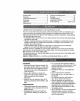
Safety Rules ................................................ 2 Warranty ..................................................... 2 Product Specifications ................................4 Assembly ................................................. 6 Operation ..................................................... 7 Maintenance._ ........................................ 11 LIMITED ONE YEAR WARRANTY Service and Adjustments ........................ Storage .....................................................
OPERATION MAINTENANCE o Do not put hands or feet near or under rotating pad& o Exercise extreme caution when operating on or crossing gravel drives, walks, or roads. Stay alert for hidden hazards or traffic. Do not carry passengers. o After striking a foreign object, stop the engine (motor), remove the wire from the spark plug, thoroughly inspect the tiller for any damage, and repair the damage before restarting and operating the tiller..
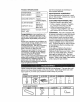
PRODUCT SPECIFICATIONS HORSEPOWER: Use the correct tools as necessary insure proper tightness. 3.75 HP MAINTENANCE I-- DISPLACEMENT: 9.03 CU_ IN. (148CC) GASOLINE CAPACITY: 2 Quarts Unleaded Regular OIL (API-SF/SG/SH): CAPACITY: 20 oz.) SPARK PLUG : GAP: .030") to AGREEMENT A Sears Maintenance Agreement is available on this product. Corrtact your nearest Sears store for details. CUSTOMER RESPONSIBILITIES o Read and observe the safety rules..
TOOLS REQUIRED FOR OPERATOR'S POSITION When right or left hand is mentioned ir this manual, it means when you are in the operating position (standing behind tiller handles)° ASSEMBLY A socket wrench set will make assembly easier, Standard wrench sizes are listed, (1) (1) (1) (2) Utility knife Pair of pliers Screwdriver 1/2" wrenches Front E ! J Left Right Operator's Position CONTENTS OF HARDWARE PACK G © (2) Hex Bolts 5/16-18 x 3/4 (2) Hex Bolts 5/16-18 x 1 (6) Hex Nuts 5/16-18 .
UNPACK DLE CARTON _CAUTION: & INSTALL Be careful of exposed HAN- Engine Bracket Halves Nut "A" sta- / ples when handling or disposing of cartoning material. IMPORTANT:: When uNpacking and assembling tiller, be careful not to stretch or kinK cable(s). = Cut cable ties securing handles. o The handle may be assembled in high or low position,, Slowly lift handle assembly up and align handle holes with desired handle panel hole and slot. = Loosely assemble hardware as shown.
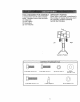
KNOWYOURTILLER READTHIS OWNER'SMANUALANDSAFETYRULESBEFOREOPERATINGYOUR TILLER, Comparethe illustrationswith yourtillerto familiarizeyourselfwith the locationofvarious controlsandadjustments.Savethis manualfor future reference. Thesesymbols may appear on your Tiller or in literature supplied with the product. Learn and understand their meaning.
The operationof anytillercan resultinforeignobjectsthrownintothe eyes, whichcan resultin severeeyedamage. Alwayswearsafetyglassesor eye shieldsbeforestartingyourtiller andwhiletilling, We recommenda widevision safetymaskoverthe spectaclesor standardsafetyglasses.
" Tilt tillerbackon its whe_lsandthen relevel o Withenginelevel,refillto pointof overflowingif necessary.Replaceoilfiller plug. o Forcoldweatheroperationyou should changeoil for easierstarting(See "OIL VISCOSITYCHART in the Customer Responsibilitiessectionof this manual).
o Start engine, tip tines off ground by pressing handles down and engage tine control to start fine rotation. Allow tines to rotate for five minutes. Then go back over the entire area at right angles. There are two reasons for doing this. First, wide turns are much easier to negotiate than about-faces_ Second, the tiller won't be pulling itself, and you, toward the row next to ito Set depth stake and wheel height for shallow tilling when working extremely hard soil or' sod.
SCHEDULE -b MAINTENANCE ¢o _ ILLOATES REGULAR SERVICE DATES SERVICE Check Engine Oil Level _ I_ Change Engine Oi! 6_'1, 2 Oil Pivot Points Inspect Spark Arrestor / Muffler Inspect Air Screen Clean or Replace Air Cleaner Cartridge i6/2 Clean Engine Cylinder Fins 6,4" Replace Spark Plug j 6/ 1 - Change more often when operating under a heavy load or In high ambient temperatures 2 - Service more often when operating In dirty or dusly conditions GENERAL LUBRICATION RECOMMENDATIONS CHART
Disconnectsparkplugwire beforeperformingany maintenance(exceptcarburetoradjustment)to preventaccidentalstartingof engine. Preventfires! Keepthe enginefree of grass,leaves,spilledoil, or fuel Remove fuel fromtankbeforetippingunitfor maintenance. Cleanmufflerareaof allgrass, dirt,anddebri& ° Refill engine with oil. See "FILL ENGINE WITH OIL" in the Operation section of this manual.
SPARK CylinderFins Mu, / Blower Housing .j Air Screen ) Replace spark plugs at the beginning of each tilling season or after every 50 hours of use, whichever comes first. Spark plug type and gap setting is shown in "PRODUCT SPECIFICATIONS" on page 4 of this manual TRANSMISSION Your transmission is sealed and will only require lubricationif it is serviced. MUFFLER Do not operate tiller without muffler. Do not tamper with exhaust system.
NARROW TILLING/CULT_VATmNG 12-3/4" PATH • Remove outer'tines. - spring and engaging tines. Loosen cable clip and push down on cable only enough to relieve spring tension. Tighten cable clip_ ° Recheck in "OFF" position arrd adjust if necessary. FINAL CHECK "ON" POSITION o With fine control "ON" (held down to handle) push down on handle to raise tines off the ground_ o Slowly pull recoil starter handle while observ!ng tine& Tines should rotate forward.
CapNutand Cap_ _er V-BELT Replace V-belt if it has stretched considerably or if it has cracks or frayed edges. Belt guard must be removed to service bell See "TO REMOVE BELT GUARD" in this section of manual. BELT REMOVAL " Remove V-belt from transmission first and then from engine pulley.
Immediatelyprepareyourtillerfor storage atthe endof the seasonor if the unitwill notbe usedfor 30 daysor more,, ,_kCAUTION: NOTE: Fuel stabilizer is an acceptable alternative in minimizing the formation of fuel gum deposits during storage. Add stabilizer to gasoline in fuel tank or storage container.
PROBLEM Will not start CORRECTION CAUSE 1, OUt of fuel 2 Engine not"CHOKED" properly & Engine flooded 1, Fill fuel tank 2, See "TO START ENGINE" inthe 4_ Dirty air cleaner 4 5. Water in fuel 5 6 Clogged fueltank 7. Loose spark plug wire, 6 Operation section 3, Wait several minutes before 8 Bad spark plug or improper gap 9 Carburetor out of adjustment Hard to start 1.
PROBLEM Engine overheats CAUSE CORRECTION 1, Low oil level/dirty oil 2 Dirty engine sir screen,. 3, Dirty engine 4. Partially plugged muffler. 5. Improper carburetor adjustment Excessive bounce/ difficult handling 1. Ground too dry and hard. 2 Wheels and depth stake incorrectly adjusted. Soil balls up or clumps 1, Ground too wet. 1. Check oil level/change oil. 2 Clean engine air screen 3. Clean cylinder fins, air screen, muf tier area. 4.
REPAIR PARTS TILLER HANDLE - - MODEL NUMBER 917.292200 ASSEMBLY 22 3 6 16 20 15 19 18 KEY NO. PART DESCRIPTION NO. 1 2 137176X574 72140512 3 4 5 6 7 8 9 11 12 13 73680500 19111116 151473 9266R 74760524 3069J 6206H 3067J 3070J 19121414 KEY NO.
REPAIR PARTS TILLER BELT GUARD - - MODEL AND PULLEY NUMBER 917.292200 ASSEMBLY _ 7 9 1 3 KEY PART NO. NO.
REPAIR PARTS TILLER WHEEL - - MODEL AND DEPTH NUMBER STAKE 917.292200 ASSEMBLY 1 6 S 15 17 18 18 1716__ 14 KEY PART NO. 1 2 3 4 5 6 7 8 9 10 11 12 DESCRIPTION KEY PART NO. 74760520 73220500 10040500 19121414 4921H 74780628 318J 9193R 73800600 9551R 317J 74760512 NO.
REPAIR PARTS TILLER - - MODEL NUMBER 917,292200 TINE ASSEMBLY 2 6 5 6 KEY NO. 1 2 3 PART DESCRIPTION NO. 106860X 4921H 106858X Tine, Outer, R H Clip, Hairpin line, Inner, RH KEY PART NO. NO.
REPAIR PARTS TILLER - - MODEL NUMBER 917.292200 TRANSMISSION 7 11 13 14 KEY PART NO. 1 2 3 4 5 6 7 8 9 10 11 DESCRIPTION NO. NO, 74610412 10040400 19092016 19091412 74760544 2606J674 9173R !32212X574 10040500 73220500 19131311 KEY PART Bolt, Hex 1/4-28 x 3/4 Gr 5 • Washer, Lock 1/4 Washer 9/32 x 1-1/4 x 16 Ga Washer 9/32 x 7/8 x 12 Ga " Bolt, Hex 5/16-18 x 2.
REPAIR PARTS TiLLER--MODEL NUMBER 917.292200 DECALS 1- 8 % 2 KEY NO. 1 2 3 4 5 6 7 8 9 10 --- PART DESCRIPTION NO. 163165 163322 110719X 118655X 120431X 162215 120075X 273871 273603 273873 163516 163517 Decal, Logo Decal, Logo Decal, Oper/Lubrication Decal, Tine Control Decal, Hand Placement Decal, ]]ne Shield Wrng Dorn Decal, Warning, Rotating ]qnes Decal, Craftsman Decal, Control Speed Decal, 3.
REPAIR PARTS TILLER - - MODEL NUMBER 917.
REPAIR PARTS TILLER BRIGGS - - MODEL & STRATTON NUMBER 917.292200 ENGINE -- MODEL NUMBER 94202, TYPE NO.
REPAnRPARTS TILLER BRIGGS - - MODEL & STRATTON NUMBER ENGINE 917.292200 -- MODEL NUMBER 94202, TYPE NO.01115-E1 8,4 883 53 1019 LABEL KIT ] REQUIRES SPECIALTOOLS TO INSTALL.
REPAIR PARTS TILLER - - MODEL NUMBER 917.292200 BRIGGS & STRATTON ENGINE -- MODEL NUMBER 94202, TYPE NO.01115-E1 KEY PART NO. NO.
REPAIR PARTS TILLER - - MODEL NUMBER 917.292200 BRIGGS & STRATTON ENGINE -- MODEL NUMBER 94202, TYPE NO.01115-E1 KEY PART NO. NO.
=orthe repair or replacement parts you need :lelivered directly to your home 3all 7 am - 7 pm, 7 days a week 1-800=366-PART I1-800-366-7278) Para ordenar piezas con entrega domicilio - 1-800-659-7084 a For in-house major brand repair service 3all 24 hours a day, 7 days a week 1=800=4-REPAIR (1-800-473-7274) Para pedir servicio de reparacibn domicilio - 1-800-676.