Owner's Manual CRRFTSMRN° F 0 TT TILLE 900 Series 24 inch Tine Width Model No. 917.299011 • EspaSol, p. 20 This product has a low emission engine which operates differently from previously built engines. Before you start the engine, read and understand this Owner's Manual. IMPORTANT: Read and follow all Safety Rules and Instructions before operating this equipment. Sears, Roebuck Visit our Craftsman and Co., Hoffman Estates, website:www.sears.com/craftsman IL 60179 U.S.A.
Manintenance......................................12 Service and Adjustments.....................15 Storage................................................17 Troubleshooting...................................18 Illustrated Parts List .............................38 Sears Service........................Back Cover Warranty ................................................2 Safety Rules..........................................2 Product Specifications...........................4 Assembly/Pre-Operation.........
• Use extension cords and receptacles as specified by the manufacturer for all units with electric drive motors or elec- • Do not overload the machine capacity by attempting to till too deep at too fast a rate. tric starting motors. • Never attempt to make any adjustments while the engine (motor) is running (except where specifically recommended by manufacturer). • Never operate the machine at high speeds on slippery surfaces. Look behind and use care when backing. • Never allow bystanders near the unit.
PRODUCT SPECIFICATIONS Gasoline 3 Qts Capacity: Unleaded OiI(API-SG-SL): (Capacity: 16 oz.) SAE 30 Plug : .030") Regular 32°F) NGK-BPR6ES TORCN-F6RTO Congratulations on making a smart purchase. Your new Craftsman® product is designed and manufactured for years of dependable operation. But like all products, it may require repair from time to time. That's when having a Repair Protection Agreement can save you money and aggravation.
These accessories were available when the tiller was produced. at most Sears retail outlets and service centers. Some of these apply to your tiller.
Your new tiller has been assembled at the factory with the exception of those parts left unassembled for shipping purposes. To ensure safe and proper operation of your tiller all parts and hardware you assemble must be tightened securely. Use the correct tools as necessary to insure proper tightness. TOOLS REQUIRED FOR ASSEMBLY A socket wrench set will make assembly easier. Standard wrench sizes are listed.
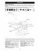
KNOW YOUR TILLER READ THIS OWNER'S MANUAL AND SAFETY RULES BEFORE OPERATING YOUR TILLER Compare the illustrations with your tiller to familiarize yourself with the locations ious controls and adjustments. Save this manual for future reference.
The operation of any tiller can result in foreign objects which can result in severe eye damage. Always wear shields before starting your tiller and while tilling. We safety glasses or a wide vision safety mask worn over HOW TO USE YOUR TILLER Know how to operate all controls adding fuel and oil or attempting engine. TILLING before to start The speed and depth of tilling is regulated by the position of the depth stake and wheel height. The depth stake should always be below the wheels for digging.
AROUND TOWN 1. 2. Disconnect spark Drain fuel tank. 3. Transport in upright oil leakage. BEFORE _f_CAUTION: Fill to within 1/2 inch of top of fuel tank to prevent spills and to allow for fuel expansion. If gasoline is accidentally spilled, move machine away from area of spill. Avoid creating any source of ignition until gasoline vapors have disappeared. Wipe off any spilled oil or fuel. Do not store, spill or use gasoline near an open flame. plug wire.
7. If the choke lever has been moved to • Tilling is digging into, turning over, and breaking up packed soil before planting. Loose, unpacked soil helps root growth. Best tilling depth is 4"-6". A tiller will also clear the soil of unwanted vegetation. The decomposition of this vegetable matter enriches the soil.
CULTiVATiNG Cultivating is destroying the weeds between rows to prevent them from robbing nourishment and moisture from the plants. At the same time, breaking up the upper layer of soil crust will help retain moisture in the soil. Best digging depth is 1 "-3". • You will probably not need to use the depth stake. Begin by tipping the depth stake forward until it is held by the stake spring.
/ / / / / MAINTENANCE SERVICE DATES REGULAR SERVICE _ #_'/ _'_'_'_M Check Engine 0il Level _'_'_ M M _ Change Engine Oil _1,2 Oil Pivot Points V _' Inspect Spark Arrester / Muffler Inspect Air Screen _/ Clean or Replace Air Cleaner Cartridge _2 Clean Engine Cylinder Fins Replace Spark Plug 1 - Change more often when operating under a heavy load or in high ambient temperatures. 2 - Service more often when operating in dirty or dusty conditions.
5. Al:_CAUTION:Disconnect spark plug wire before performing any maintenance to prevent accidental starting of engine. Prevent fires! Keep the engine free of grass, leaves, spilled oil, or fuel. Remove fuel from tank before tipping unit for maintenance. Clean muffler area of all grass, dirt, and debris. Do not touch hot muffler or cylinder fins as contact may cause burns. Refill engine with oil. See "FILL ENGINE WITH OIL" in the Operation section of this manual.
COOLING SYSTEM SPARK Your engine is air cooled. For proper engine performance and long life keep your engine clean. • Clean air screen frequently using a stiff-bristled brush. PLUG Replace spark plugs at the beginning of each tilling season or after every 25 hours of use, whichever comes first. Spark plug type and gap setting are shown in "PRODUCT SPECIFICATIONS" on page 4 of this manual. TRANSMISSION • Remove blower housing and clean as necessary. • Keep cylinder fins free of dirt and chaff.
• Assemble holes '_' in tine hubs to holes "C" in tine shaft. _CAUTION: Disconnect spark plug wire from spark plug and place wire where it cannot come into contact with plug. TILLER TO ADJUST HANDLE -Ac HEIGHT Io® Factory assembly has provided lowest handle height. Select handle height best suited for your tilling conditions. Handle height will be different when tiller digs into soil. 1. If a higher handle height is desired, loosen the four nuts securing handle panel to engine brackets. 2.
TO REPLACE 5. With tine control "ON" (held down to handle) push down on handle to raise tines off the ground. 6. Slowly pull recoil starter handle while observingtines. Tines should rotate forward. 7. If tines do not rotate, inner wire of control cable is too loose. Loosen cable clip and pull cable up to remove slack and retighten clip. 8. Recheck in "ON" position and adjust if necessary.
Immediately prepare your tiller for storage at the end of the season or if the unit will NOTE: Fuel stabilizer is an acceptable alternative in minimizing the formation of fuel gum deposits during storage. Add stabilizer to gasoline in fuel tank or storage container. Always follow the mix ratio found on stabilizer container. Run engine at least 10 minutes after adding stabilizer to allow the stabilizer to reach the carbu- not be used for 30 days or more.
TROUBLESHOOTING CHART: See appropriate section in manual PROBLEM Will not start Hard to start Loss of power Engine overheats unless directed CAUSE to Sears service center CORRECTION 1 Out of fuel. 1 Fill fuel tank. 2 Fuel valve "OFF" 2 Turn fuel valve to the "ON" position. 3 Engine Switch "OFF" 3 Turn engine switch to the "ON" position. 4 Engine not "CHOKED" 4 See"TO section. 5 Engine flooded. 5 Wait several to start. 6 Bad spark plug or improper gap.
TROUBLESHOOTING CHART: See appropriate section in manual unless directed to Sears service center PROBLEM CAUSE CORRECTION 1 Ground too dry and hard. 1 Moisten ground or wait for more favorable soil conditions 2 Wheels and depth stake incorrectly adjusted. 2 Adjust wheels and depth stake. Soil bails up or clumps 1 Ground too wet. 1 Wait for more favorable Engine runs 1 Tine control is not engaged. 1 Engage tine control 2 V-belt not correctly adjusted.
Garantia ....................................................... 20 Reglas de Seguridad ................................... Especificaciones del producto ..................... Montaje/Pre Operaci6n ................................ Operaci6n .................................................... Programa De Mantenimiento ....................... 20 22 24 25 30 GARANTiA Mantenimiento ............................................. 30 Servicio y Ajustes ........................................
OPERACION • No ponga ni las manos ni los pies cerca o debajo de las piezas rotatorias. • Tenga mucho cuidado cuando opere o cruce entradas para autom6viles de ripio, senderos o caminos. Este alerta en Io que se refiere a los peligros escondidos o al tr&fico. No Ileve pasajeros. • Despues de pegarle a un objeto extraflo, pare el motor, remueva el alambre de la bujia, inspeccione la cultivadora cuidadosamente, para verificar si hay daflos, y repare el daflo antes de volver a arrancar y operar la cultivadora.
ESPECIFICACIONES DEL PRODUCTO Capacidad de Gasotina: 3 Cuartos Sin ptomo, Regular Aceite (API-SG-SL): (Capacidad: 16 oz.) SAE 30 (Sobre 32°F) SAE 5W-30 (Debajo 32°F) Bujia : (Abertura:0,030") NGK-BPR6ES TORCH-F6RTC ACUERDOS DE PROTECCION PARA LA REPARACI6N Congratulaciones por su buena compra. Su nuevo producto Craftsman® est& diseSado y fabricado para funcionar de modo fiable por muchos aSos. Pero como todos los productos, puede necesitar alguna reparaci6n de tanto en tanto.
Estos accesorios estaban disponibles cuando se produjo la cultivadora. Tambien estan disponibles en la mayoria de las tiendas de Sears yen los centros de servicio. Algunos de estos accesorios tal vez no se apliquen a su cultivadora.
Su cultivadora nueva ha sido montada en la f&brica, con la excepci6n de aquellas partes que se dejaron sin montar pot razones de envio. Para asegurarse que la cultivadora operara en forma segura y adecuada, todas las partes y los articulos de ferreteria que monte tienen que estar apretados en forma segura. Use las herramientas correctas segQn sea necesario, para asegurarse de que queden apretadas en forma segura.
CONOZCA SU CULTIVADORA LEA ESTE MANUAL DEL DUEllO Y LAS REGLAS DE SEGURIDAD ANTES DE OPERAR SU CUTIVADORA Compare las ilustraciones con su cultivadora para familiarizarse con la ubicaci6n de los diversos controles y ajustes. Guarde este manual para referencia en el futuro. Estos simbolos pueden apareser producto. Aprenda y comprenda sobre su cultivadora sus significados.
La operaci6n de cualquier cultivadora puede hacer que salten objetos extranos dentro de sus ojos, Io que puede producir da_os graves en estos. Siempre use anteojos de seguridad o protecciones para los ojos antes de hacer arrancar su cultivadora o mientras este labrando con ella. Recomendamos el uso de la m&scara de seguridad de visi6n amplia, para uso sobre los espejuelos o anteojos de seguridad est_.ndar.
ENLA ClUDAD 1. Desconecte el alambrede labujia. 2. Dreneel estanquedecombustible. 3. Transp6rtela en la posiciSnderechahacia arribaparaevitarlafugadelaceite. ANTES DE ARRANCAR EL MOTOR _i_PRECAUCl6N: Llene el estanque de combustible hasta dentro de 1/2 pulgada de la parte superior para evitar los derrames y para permitir que se expanda el combustible. Si por casualidad se derrama la gasolina, aleje la m6.quina del 6.rea del derrame.
Si est& forzandola o si la cultivadora esta vibrando, quiere decir que las ruedas y la estaca de profundidad no estan ajustadas en forma adecuada para el terreno que se esta labrando. El ajuste adecuado de las ruedas y de la estaca de profundidad se Iogra al probarlas en acci6n y depende de las condiciones del suelo. (Mientras mas duro o m&s mojado este el suelo, menor es la velocidad necesaria del motor y de los brazos.
CULTIVO El cultivo quiere decir la destrucci6n de la mala hierba entre las filas para evitar que estas le roben la nutrici6n y la humedad alas plantas. AI mismo tiempo, si se rompe la capa superior de la costra del suelo, este puede retener la humedad. La mejor profundidad de excavaci6n es de 1" a 3". • Probablemente no va a necesitar usar la estaca de profundidad. Empiece por inclinar la estaca de profundidad hacia adelante, hasta que quede sujeta en el resorte de la estaca.
PROGRAMA DE MANTENIMIENTO LLENE LAS FECHAS DE MEDIDA QUE COMPLETE SU SERVICIO REGULAR Revisar Cambiar Aceitar FECHAS et nivet del aceite del motor et aceite del motor los puntos de pivote lnspeccionar et supresor lnspeccionar la rejitta de aire Limpiar/cambiar Limpiar las aletas Cambiar la bujia DE SERVICIO del sitenciador et cartucho del citindro del fittro de aire del motor 1- Cambiar mAs menudo cuando se opere bajo carga pesada o en ambientes con altas temperaturas.
2. _,PRECAUCl6N: Desconecte el alambre de la bujia antes de dar mantenimiento (excepto pot el ajuste del carburador) para evitar que el motor arranque por accidente. lEvite los incendios! Mantenga el motor sin cesped, hojas, aceite o combustible derramado. Remueva el combustible del estanque antes de inclinar la unidad para darle mantenimiento. Limpie el cesped, la mugre y la basura del &tea del silenciador.
SISTEMADE ENFRIAMIENTO Su motor se enfria con aire. Para obtener el rendimiento del motor adecuado y larga duraci6n mantenga su motor limpio. • Limpie la rejilla de aire frecuentemente usando un cepillo de cerdas duras. • Remueva la caja del ventilador y limpiela si es necesario. • Mantenga las aletas del cilindro sin mugre o paja. BUJiA Cambie las bujias al comienzo de cada temporada de cultivo, o despues de 50 horas de uso, Io que suceda primero.
LABRADO DEANCHO _IPRECAUCl6N: Desconecte el alambre de la bujia y p6ngalo en donde no pueda entrar en contacto con la bujia. CU LTIVADO RA MEDIANO-PASO DE 22" • Monte los agujeros '_' en los cubos de los brazos con los agujeros "C" en el eje de los brazos. PARA AJUSTAR LA ALTURA DEL MANGO El montaje en la f&brica se ha realizado usando la altura m&s baja del mango. Seleccione la altura del mango que mejor se acomode a sus condiciones de labraci6n.
REVISION FINAL EN LA POSICION DE "EN- PARA CAMBIAR LA CORREA V Cambie la correa V si se ha estirado considerablemente o si est& partida o si los bordes est&n desgastados. 1. La protecci6n de la correa tiene que removerse para darle servicio a la correa. Vea "PARA REMOVER LA PROTECCION DE LA CORREA" en esta secci6n de este manual. REMOCION DE LA CORREA CENDIDO" (ON) 5.
AVlSO: El estabilizador de combustible es una alternativa aceptable para reducir a un minimo la formaci6n de dep6sitos de goma en el combustible durante el periodo de almacenamiento. Agregue estabilizador a la gasolina en el estanque de combustible o en el envase para el almacenamiento. Siempre siga la proporci6n de mezcla que se encuentra en el envase del estabilizador. Haga funcionar el motor por Io menos 10 minutos despues de agregar el estabilizador, para permitir que este Ilegue al carburador.
IDENTIFICACION Yea la secci6n DE PROBLEMAS: apropiada PROBLEMA No arranca No arranca facilidad P_rdida de potencia con en el manual a menos que este dirigido a un centro de servicio Sears. CORRECCION CAUSA 1 Se acab6 el combustible. 1 Llene el tanque de combustible. 2 La v&tvuta de combustible est& en la posici6n -OFF,, (apagado) 2 Gire ta v&tvuta de combustible hasta la posici6n-ON>, (encendido).
IDENTIFICACION Yea la secci6n DE PROBLEMAS: apropiada PROBLEMA El nivet de aceite esta bajo/el aceJte esta sucio. 1 Controte el nivel de aceite/cambie 2 La rejilla de aire del motor esta sucia. 2 Limpie la rejilla de aire del motor. 3 Et motor esta sucio. 3 Limpie las atetas det cilindro, la rejilla de aire y el Area del silenciador El sitenciador esta parcialmente tapado 4 Retire el silenciador y limpielo.
TILLER - - MODEL NUMBER 917.299011 HANDLES 35 38 19 35 / 36 f 29 20 / / / / / / / / / / / / / / / KEY NO. PART NO. DESCRIPTION 1 3 12 13 14 19 20 29 137118 165787 98000129 STD533107 181476 188532 188555 12000059 Panel, Control Grip, Handle Nut, Flange Bolt, Carriage 5/16-18 x 3/4 Assembly, Panel and Tube Lever, Control, Tine Pin, Pivot Retainer, Ring / KEY NO. PART NO.
TILLER - - MODEL NUMBER BELT GUARD AND PULLEY ASSEMBLY 917.299011 8 6 25 21 14 13 2O 7 beltguard KEY NO. PART NO. DESCRIPTION 1 2 3 4 5 6 7 8 9 10 11 12 23230506 130812 86777 74770508 17490440 422920 170488 139155 165768X615 109227X 9484R 9180R Screw Set 5/16-18 x 3/8 Patch Sheave, Engine Screw, Tap Hex Head Bolt, Hex Head 5/16-24 unfx 1/2 Bolt, Thd Roller 1/4-20 x 2-1/2 Shield, Inner Belt Guard Screw Hex Wsh Hd #8-18 x 1/2 Spacer Split Guard, Belt Pad, Idler Clip, Cable V-Belt LCT KEY NO.
TILLER - - MODEL NUMBER WHEEL AND DEPTH STAKE ASSEMBLY 917.299011 9 6 11 16 21 24 17 25 25 19 17 20 19 16 wheehd.stake KEY PART NO. NO. DESCRIPTION 1 2 3 4 5 6 7 8 9 10 11 13 15 Pin, Clevis Bolt, Hex Head 5/16-18 x 1-1/4 Bolt, Hex Head 5/16-18 x 3/4 Nut Washer, Lock 5/16 Locknut, w/washer 3/8-16 Clip, Hairpin Support, Depth Stake, R.H. Stake, Depth Pin, Clevis Bolt, Hex 3/8-16 x 1-3/4 Support, Depth Stake, L.H.
TILLER - - MODEL NUMBER 917.299011 TINE ASSEMBLY 2 / / / / 6 tine_ipb_3 KEY PART NO. NO. DESCRIPTION 1 2 3 4 Tine, Outer, R.H. Retainer, Spring Zinc Tine, Inner, R.H. Tine, Inner, LH. 156926 3146R 156924 156923 KEY NO. PART NO. DESCRIPTION 5 6 156925 4929H Tine, Outer, LH. Pin, Clevis NOTE: All component dimensions given in U.S.inches. 1 inch = 25.
TILLER - - MODEL NUMBER 917.299011 TRANSMISSION 2O 2 ' / 3 8 14 15 15 12 transmission KEY NO. PART NO. DESCRIPTION 1 2 3 5 6 7 8 11 12 14 74760524 STD523732 STD551037 STD541437 9056R615 188195 165834 187912 151222 9173R Bolt, Hex 5/16-18 x 1-1/2 Gr. 2 Bolt, Fin, Hex 3/8-16 × 3-1/4 Washer 13/32 x 13/16 x 11 Locknut, w/washer 3/8-16 Shield, Tine Bracket, Engine, R.H. Bracket, Engine, L.H. Bolt, Shoulder 5/16-18 uric x 2.5 Transmission Spacer, Split KEY PART NO. NO.
TILLER - - MODEL NUMBER 917.299011 DECALS 12 / / / /! L KEY NO. PART NO. DESCRIPTION 1 2 4 5 6 8 11 12 423884 425502 425503 137539 120431X 162215 120075× 425501 425340 Decal, LCT900 Decal, Bettguard Decal, Tine Shield Decal, Cntrl Pnt Inst.
TILLER = - MODEL NUMBER 917.
TILLER = - MODEL NUMBER 917.299011 ENGINE, LCT -- MODEL NUMBER PLMHK14600124P-BPQE2 KEY PART NO. NO.
o Find this and aLLyour other product manuals onLine. o Get answers from our team of home experts. o Get a personalized maintenance plan for your home. o Find information and tools to help with home projects. Your Home For repair - in your home - of all major brand appliances, lawn and garden equipment, or heating and cooling systems, no matter who made it, no matter who sold it! For the replacement parts, accessories and owner's manuals that you need to do-it-yourself.