Owner's Manual CRRFT$14RH ° TI ETLL TE ROTATI COU IT GT 900 Series 14 Inch Tine Width Model No. 917.299061 \ • EspaSol, p. 22 This product has a low emission engine which operates differently from previously built engines. Before you start the engine, read and understand this Owner's Manual. IMPORTANT: Read and follow all Safety Rules and Instructions before operating this equipment. Sears, Roebuck Visit our Craftsman and Co., Hoffman website:www.sears.com/craftsman 428425 Rev.
Safety Rules .......................................... Warranty ................................................ Product Specifications ......................... Assembly/Pre-Operation ....................... Operation ............................................... Maintenance ........................................ LIMITED ONE YEAR WARRANTY 2 2 4 6 8 13 Service and Adjustments ..................... 15 Storage ................................................ 19 Troubleshooting ........................
• Use extension cords and receptacles as specified by the manufacturer for all units with electric drive motors or elec- • Never operate the machine at high speeds on slippery surfaces. Look behind and use care when backing. • Never allow bystanders near the unit. • Use only attachments and accessories approved by the manufacturer of the tiller. tric starting motors. • Never attempt to make any adjustments while the engine (motor) is running (except where specifically recommended by manufacturer).
PRODUCT Gasoline SPECIFICATIONS Capacity: In the state of California SAE 30 (Above 32°F) (Capacity:20oz./0.6L) SAE 5W-30 (Below 32°F) Spark Plug: NGK-BPR6ES (Gap: .030"/0.76mm) TORCH-F6RTC REPAIR PROTECTION AGREEMENTS CONGRATULATIONS on your purchase of a Sears Tiller. It has been designed, engineered and manufactured to give you the best possible dependability and performance. Congratulations on making a smart purchase.
These accessories were available when the tiller was produced. at most Sears retail outlets and service centers. Some of these apply to your tiller. They are also available accessories may not ENGINE SPARK PLUG MUFFLER AiR FILTER GAS CAN ENGINE OiL STABiLiZER TILLER PERFORMANCE FURROW OPENER TILLER MAINTENANCE BELT SHEAR PiN HAiRPiN CLiP CD CONTENTS OF HARDWARE PACK G (2) Handle Locks (1) Carriage Bolt 3/8-16 UNC x 1 Gr.
Your new tiller has been assembled at the factory with the exception of those parts left unassembled for shipping purposes. To ensure safe and proper operation of your tiller all parts and hardware you assemble must be tightened securely. Use the correct tools as necessary to insure proper tightness. TOOLS REQUIRED ASSEMBLY A socket wrench easier.
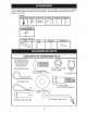
Handle Column Cables Cable Clip Loosen Handle Lock Lever to Move handles CONNECT 4. 5. 6. 7. Insert end of shift rod farthest from bend into hole of shift lever indicator. 2. Insert hairpin rod to secure side. end of Hairpin \Clip Shift Lever Indicator Shift Rod REMOVE Lever 1. Adjust handle assemby to lowest position. Be sure lock lever is tightened securely. 2. Make sure shift lever indicator is in "N" \ Slot Rear Cartridge Bolt 3. / 4.
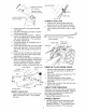
These symbols may appear on your Tiller or in literature supplied with the product, Learn and understandtheir meaning, KNOW YOUR TILLER READ THIS OWNER'S TILLER. MANUAL AND SAFETY RULES BEFORE OPERATING Compare the illustrations with your tiller to familiarize yourself various controls and adjustments. Save this manual for future YOUR with the location reference.
The operation of any tiller can result in foreign objects thrown into the eyes, which can result in severe eye damage. Always wear safety glasses or eye shields before starting your tiller and while tilling. We recommend a wide vision safety mask over spectacles or standard safety glasses. HOW TO USE YOUR TILLER Know how to operate all controls adding fuel and oil or attempting engine.
3. AROUND Hold the drive control bar against the handle to start tilling movement. Tines and wheels will both turn. 4. Move throttle control to "FAST" position for deep tilling. To cultivate, throttle control can be set at any desired speed, depending on how fast or slow you wish to cultivate. IMPORTANT: Always release drive control bar before moving shift lever into another position. Depth Stake Pin "RELEASED" Position 1. 2. Disconnect spark Drain fuel tank. 3. Transport in upright oil leakage.
Fuel Valve _iILCAUTION: Fill to within 1/2 inch of top of fuel tank to prevent spills and to allow for fuel expansion. If gasoline is accidentally spilled, move machine away from area of spill. Avoid creating any source of ignition until gasoline vapors have disappeared. Wipe off any spilled oil or fuel. Do not store, spill or use gasoline near an open flame.
ADJUST WHEELS CULTIVATING 1. 2. 3. 4. CULTIVATING FOR Place blocks under right hand side of tiller and remove hairpin clip and clevis pin from right hand wheel. Move wheel outward approximately 1 inch until hole in inner wheel hub lines up with inner hole in axle. Replace clevis pin and hairpin clip on inside of wheel and remove blocks. Repeat side.
/ / / / / MAINTENANCE SERVICE DATES REGULAR SERVICE _'_'_'_ _'_'_"_'x M Check Engine 0il Level M M _ _ Change Engine Oil _1,2 Oil Pivot Points V _' Inspect Spark Arrester / Muffler Inspect Air Screen _' _' Clean or Replace Air Cleaner Cartridge _2 Clean Engine Cylinder Fins Replace Spark Plug 1 - Change more often when operating under a heavy load or in high ambient temperatures. 2 - Service more often when operating in dirty or dusty conditions.
5. _L, CAUTION: Disconnect spark plug wire before performing any maintenance (except carburetor adjustment) to prevent accidental starting of engine. Prevent fires! Keep the engine free of grass, leaves, spilled oil, or fuel. Remove fuel from tank before tipping unit for maintenance. Clean muffler area of all grass, dirt, and debris. Do not touch hot muffler or cylinder fins as contact may cause burns. Refill engine with oil. See "CHECK ENGINE OIL LEVEE' in the Operation section of this manual.
COOLING SYSTEM SPARK PLUG Your engine is air cooled. For proper engine performance and long life keep your engine clean. • Clean air screen frequently using a stiff-bristled brush. Replace spark plugs at the beginning of each tilling season or after every 25 hours of use, whichever comes first. Spark plug type and gap setting are shown in "PRODUCT SPECIFICATIONS" on page 4 of this manual. TRANSMISSION • Remove blower housing and clean as necessary. • Keep cylinder fins free of dirt and chaff.
TIRE / CARE _ILCAUTION: When mounting tires, unless beads are seated, ovednflation can cause an explosion. • Maintain 20 pounds of tire pressure. If tire pressures are not equal, tiller will pull to one side. • Keep tires free of gasoline or oil which can damage rubber. TO REMOVE WHEEL . 2. 3. 4. Place blocks under transmission keep tiller from tipping. Remove hairpin clip and clevis wheel. Remove wheel and tire. Repair Belt Guard Hex \ and Washer (Located Behind Tire) Screws Hairpin Clip and C
TINE REPLACEMENT J_,CAUTION: Tines are sharp. gloves or other protection when tines. • To maintain the superb mance of this machine Wear handling be checked for sharpness, wear, and bending, particularly the tines which are next to the transmission. If the gap between the tines exceeds 3-1/2 inches A badly worn tine causes your tiller to work harder and dig more shallow. Most important, worn tines cannot chop and shred organic matter as effectively nor bury it as deeply as good tines.
ENGINE TO ADJUST Maintenance, repair, or replacement of the emission control devices and systems, which are being done at the customers expense, may be performed by any non-road engine repair establishment or individual. Warranty repairs must be performed by an authorized engine manufacturer's service outlet. iMPORTANT: Never tamper with the engine governor, which is factory set for proper engine speed. Overspeeding the engine above the factory high speed setting can be dangerous.
Immediately prepare your tiller for storage at the end of the season or if the unit will NOTE: Fuel stabilizer is an acceptable alternative in minimizing the formation of fuel gum deposits during storage. Add stabilizer to gasoline in fuel tank or storage container. Always follow the mix ratio found on stabilizer container. Run engine at least 10 minutes after adding stabilizer to allow the stabilizer to reach the carbure- not be used for 30 days or more.
TROUBLESHOOTING CHART: See appropriate section in manual unless directed to Sears service center PROBLEM Will not start Hard to start Loss of power Engine overheats CAUSE CORRECTION 1 Out of fuel. 1 Fill fuel tank. 2 Fuel valve "OFF" 2 Turn fuel valve to the "ON" position. 3 Engine Switch "OFF" 3 Turn engine switch to the "ON" position. 4 Engine not "CHOKED" 4 See"TO section. 5 Engine flooded. 5 Wait several to start. 6 Bad spark plug or improper gap.
TROUBLESHOOTING CHART: See appropriate section in manual unless directed to Sears service center PROBLEM CAUSE CORRECTION Excessive 1 Ground too dry and hard. 1 bounce/ difficult handling Moisten ground or wait for more favorable soil conditions 2 Wheels and depth stake incorrectly adjusted. 2 Adjust wheels and depth stake. Soil bails up or clumps 1 Ground too wet. 1 Wait for more favorable Engineruns buttiller won't 1 Tine control is not engaged.
Reglas de Seguridad ................................... Garanfia ....................................................... Especificaciones del producto ..................... Montaje/Pre Operaci6n ................................ Operaci6n .................................................... Mantenimiento ............................................. GARANTIA 22 22 24 26 28 33 Programa de Mantenimiento ....................... 33 Servicio y Ajustes ....................................... 35 AImacenamiento .
MANTENIMIENTO • Despues de pegarle a un objeto extraflo, pare el motor, remueva el alambre de la bujia, inspeccione la cultivadora cuidadosamente, para verificar si hay daflos, y repare el daflo antes de volver a arrancar y operar la cultivadora. • Tenga cuidado para evitar resbalarse o caerse. • Si la unidad empieza a vibrar anormalmente, pare el motor y revisela inmediatamente para verificar la causa. La vibraci6n normalmente es un aviso de problemas.
ESPECIFICACIONES DEL PRODUCTO Capacidad de gasotina: 3 Cuartos (2.8L) Sin ptomo, regular Aceite (API-SG-SL): (Capacidad:20 oz./0.6L) SAE 30 (Sobre 32°F) SAE 5W-30 (Debajo 32°F) Bujia: (Abertura: .030"/0.76mm) NGK-BPR6ES TORCH-F6RTC ACUERDOS DE PROTECCK_N PARA LA REPARACION Congratulaciones por su buena compra. Su nuevo producto Craftsman® est& diseSado y fabricado para funcionar de modo fiable por muchos aSos. Pero como todos los productos, puede necesitar alguna reparaci6n de tanto en tanto.
Estos accesorios estaban disponibles cuando se produjo la cultivadora. Tambien est&n disponibles en la mayoria de las tiendas de Sears yen los centros de servicio. Algunos de estos accesorios tal vez no se apliquen a su cultivadora.
Su cultivadora nueva ha sido montada en la f&brica, con la excepci6n de aquellas partes que se dejaron sin montar por razones de envio. Para asegurarse que la cultivadora operara en forma segura y adecuada, todas las partes y los articulos de ferreteria que monte tienen que estar apretados en forma segura. Use las herramientas correctas, seg0n sea necesario, para asegurarse de que queden apretadas en forma segura.
Conjunto det mango posoci6n 'Arriba" Cotumna det Mango Cables Abrazadera del Cable Suette la patanca de cierre del mango para moverla CONEXION DE LA VARILLA DE CAMBIO 1. Inserte el extremo de la varilla de cambio que est& mgts alejado de la dobladura, en el agujero del indicador de la palanca de cambio. 2. Inserta la abrazadera de horquilla a traves del agujero de la varilla de cambio para asegurarla con la junta de la abrazadera sobre el lado derecho. 4.
Estos simbolos pueden apareser sobre su cultivadora en la literature proporcionada ducto, aprenda y comprenda sus significados. CONOZCA con el pro- SU CULTIVADORA LEA ESTE MANUAL DEL DUENO Y LAS REGLAS CULTWADORA DE SEGURIDAD ANTES DE OPERAR SU Compare las ilustraciones con su cultivadora para familiarizarse con la ubicaci6n diversos controles y ajustes. Guarde este manual para futura referencia.
La operaci6n de cualquier cultivadora puede hacer que salten objetos extraflos dentro de sus ojos, Io que puede producir daflos graves en estos. Siempre use anteojos de seguridad o protecciones para los ojos antes de hacer arrancar su cultivadora o mientras este labrando con ella. Recomendamos el uso de la m&scara de seguridad de visi6n amplia, para uso sobre los espejuelos o anteojos de seguridad est&ndar.
3. Sujetelabarrade controldela impulsi6n en contradelmangoparaempezarconel movimiento de labraci6n.Tantolosbrazos comolasruedasvana girar. 4. Muevael controlde laaceleraci6na la posici6nde"RAPIDO"(FAST)paraun labradoprofundo.Paracultivar,elcontrolde la aceleraci6npuedesetajustadoa cualquier velocidaddeseada,dependiendo decu&n rapidoo cuanlentodeseehacerel cultivo. IMPORTANTE: Siempresueltela barradecontrol de laimpulsi6nantesde moverla palanca decambioa otraposici6n.
AGREGUE GASOLINA • Llene el estanque de combustible. Llene hasta la parte inferior del cuello de relleno del estanque de gasolina. No Io Ilene demasiado. Use gasolina regular, sin plomo, nueva y limpia con el minimo de 87 octanos. (El uso de gasolina con plomo aumentar& los dep6sitos de 6xido de plomo y carbono y se reducir& la duraci6n de la v&lvula). No mezcle el aceite con la gasolina.
CONSEJOS PARA LABRAR _PRECAUCl6N:Antes de acostumbrarse a manejar su cultivadora, empiece el uso de esta en el terreno con la aceleraci6n en la posici6n de "lento" (SLOW). • El labrar quiere decir el excavar, dar vuelta y romper el suelo duro antes de plantar. El suelo suelto y blando permite el desarrollo de las raices. La mejor profundidad de labrar es 4" a 6". La cultivadora tambien puede despejar el suelo de las malezas indeseables. La descomposici6n de estas malezas enriquece el suelo.
PROGRAMA DE MANTENIMIENTO Zo// /_/ LLENE LAS FECHAS DE MEDIDA /_'/_"bOi%_?< o SERVIClO REGULAR Revisar et nivet del aceite del motor / _ O O / / o4 O _ FECHAS DE SERVlCIO if Cambiar el aceite del motor Aceitar los puntos de pivote _' Inspeccionar et supresor del sitenciador Inspeccionar la rejitta de aire Limpiar/cambiar et cartucho del fittro de aire Limpiar las aletas del citindro del motor v' L.,-.,-.,.
3. _L',PRECAUCl0N: Desconecte e! alambre de la bujia antes de dar mantenimiento (excepto pot el ajuste del carburador) para evitar que el motor arranque pot accidente. lEvite los incendios! Mantenga el motor sin cesped, hojas, aceite o combustible derramado. Remueva el combustible del estanque antes de inclinar la unidad para darle mantenimiento. Limpie el cesped, la mugre y la basura del &tea del silenciador.
EL SISTEMA DE ENFRIAMIENTO LAS Este motor es un motor enfriado por aire. Para obtener un rendimiento adecuado del motor y una mayor vida Otil, mantengalo BUJiAS Reemplace las bujias al comienzo de la temporada de arado o despues de cada 25 horas de uso, Io que ocurra primero. El tipo de bujfa y el ajuste de la separaci6n de los electrodos se muestran en ,,ESPECIFICACIONES DEL PRODUCTO_ en la limpio. • Limpie la rejilla de aire frecuentemente con un cepillo de cerdas duras.
CUIDADO DE LAS LLANTAS Protecci6n de la correa ,_PRECAUCI6N: Cuando monte las Ilantas, a menos que los talones esten asentados, si se inflan demasiado se puede producir una explosi6n. • Mantenga 20 libras de presi6n en las Ilantas. Si la presi6n de las Ilantas no es la misma, la cultivadora va a tirar hacia un lado. • Mantenga las Ilantas sin gasolina o aceite, porque pueden dahar el caucho. PARA REMOVER LA RUEDA 1. Ponga los bloques debajo de la transmisi6n para evitar que se vuelque la cultivadora. 2.
CAMBIO DE BRAZOS • Para que esta m&quina pueda mantener un rendimiento excelente en el labrado, se deben revisar los brazos para verificar si est&n afilados, desgastados o doblados, especialmente los que se encuentran al lado de la transmisi6n. Si el espacio libre entre los brazos es m&s de 3-1/2 pulgadas, se tienen que cambiar o enderezar, seg0n sea necesario. • Los brazos nuevos tienen que montarse segQn se muestra en la Fig. X3. Los bordes de los brazos afilados rotar&n hacia atr&s desde arriba.
PARA AJUSTAR EL CARBURADOR El carburador tiene un chorro de alta velocidad y ha sido preajustado en la f&brica y no deberia necesitar ajustes. Sin embargo, se pueden necesitar ajustes de menor importancia para compensar por las diferencias en el combustible, temperatura, altura o carga. Si el carburador necesita ajustes, pongase en contacto con su centro/departamento de servicio autorizado m&s cercano.
AVlSO: El estabilizador de combustible es una alternativa aceptable para reducir a un minimo la formaci6n de dep6sitos de goma en el combustible durante el periodo de almacenamiento. Agregue estabilizador a la gasolina en el estanque de combustible o en el envase para el almacenamiento. Siempre siga la proporci6n de mezcla que se encuentra en el envase del estabilizador. Haga funcionar el motor pot Io menos 10 minutos despues de agregar el estabilizador, para permitir que este Ilegue al carburador.
IDENTIFICACION Yea la secci6n DE PROBLEMAS: apropiada PROBLEMA No arranca No arranca facilidad P_rdida de potencia con en el manual a menos que este dirigido a un centro de servicio Sears. CORRECCION CAUSA 1 Se acab6 el combustible. 1 Llene el tanque de combustible. 2 La v&tvuta de combustible est& en la posici6n -OFF,, (apagado) 2 Gire ta v&tvuta de combustible hasta la posici6n-ON>, (encendido).
IDENTIFICACION Yea la secci6n DE PROBLEMAS: apropiada PROBLEMA El nivet de aceite esta bajo/el aceJte esta sucio. 1 Controte el nivel de aceite/cambie 2 La rejilla de aire del motor esta sucia. 2 Limpie la rejilla de aire del motor. 3 Et motor esta sucio. 3 Limpie las atetas det cilindro, la rejilla de aire y el Area del silenciador El sitenciador esta parcialmente tapado 4 Retire el silenciador y limpielo.
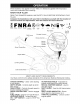
TILLER - - MODEL NUMBER 917.299061 HANDLES 4 / 27 \ 26 24 21 20 KEY PART NO. NO. 2 3 4 5 6 7 9 10 11 12 13 14 15 16 17 141406 110673X 127254X 6712J 189347 110641X 72010520 110646X 4497H 81328 187497 109313X 110702X STD533710 109229X 19 DESCRIPTION Grip, Handle Grommet, Handle Bar, Drive Control Assembly Cap, Vinyl Panel, Control Bushing, Split Bolt, 5/16-18 x 2-1/2 Handle, Grip Retainer Spring Bolt, Shoulder Handle, Shift Grommet, Rubber Rod, Shift Bolt 3/8-16 x 1 Gr.
TILLER MAINFRAME, LEFT SIDE - - MODEL NUMBER 917.299061 7 6 9 65 38 37 67 34 31 _69 30 23 24 40 26 15 i i mainflame KEY NO. PART NO. 3 4 5 6 7 8 9 STD541037 432420 164329 110111× STD532505 8700J 86777 10 12 13 14 15 16 19 21 22 23 9484R 73510400 23230506 156117 STD551031 145102 12000028 110652× 74770508 428353 183122×613 795R 126875× 4497H 165501×613 24 25 26 DESCRIPTION Nut, Hex 3/8-16 Shield, Inner Belt Guard Pin Spiral Flared Lever, Shift Bolt, Carriage 1/4-20 x 1/2 Gr.
TILLER MAINFRAME, RIGHT SiDE - - MODEL NUMBER 917.299061 15 II \\ 13 12 5 I / / 11 22 / 44 main frame_rig ht_LCT_3 10 KEY NO. PART NO. DESCRiPTiON 2 5 7 I0 11 12 13 73970500 102332× 102173× 74760524 4497H 126875X 428353 183122X613 795R Locknut, He×, Flange 5/16-18 Bracket, Reinforcement Counter Weight, R.H. Bolt, Hex 5/16-18 x 1-1/2 Retainer, Spring Rivet, Drilled Tire Rim Tire Valve KEY PART NO. NO. 15 44 73510600 DESCRIPTION Engine, (See Breakdown) LOT Model No.
TILLER - - MODEL NUMBER 917.299061 TRANSMISSION 12 11 10 6O 48 9 14 6 5 44 51 58 transmission 19.5b KEY PART NO. NO. 1 188554 188482 3 4 5 6 7 8 9 10 11 12 13 14 15 16 18 19 2O 161963 5020J 1370H 137335 145101 4895H 154467 7392M 100371K 106160X 142145 8353J 12000039 154466 4358J 12000040 102114X 21 22 23 24 25 27 28 29 102115X 6803J 102111X STD551143 STD541143 143009 106390X 102134X DESCRIPTION Transmission Assembly (Includes Key Nos. 2-52) Gearcase, L.H. w/Bearing (Includes Key No.
TILLER - - MODEL TINE NUMBER 917.299061 SHIELD 7 8 29 \ 23 // 24 27 i 26 tine shield 29 14 in rl KEY NO. PART NO.
TILLER - - MODEL NUMBER 917.299061 TINE ASSEMBLY 6 / 3 1 i. i 11 i 2 q 10 4 9 9 tine_ipb_99_2 KEY NO. PART NO. DESCRIPTION 1 2 3 4 5 6 8 4459J 132673 6554J 3146R 132721 73540600 74610616 Tine, Outer, LH. Pin, Shear Tine, Inner, L.H. Clip, Hairpin Assembly, Hub and Plate, L.H. Nut Crowntock 3/8-24 Bolt, Hex 3/8-24 x 1 KEY NO. PART NO. DESCRIPTION 9 10 11 4460J 132722 6555J Tine, Outer, R.H. Assembly, Hub and Plate, R.H. Tine, Inner, R.H. NOTE: All component dimensions given in U.S.
TILLER - - MODEL NUMBER 917.299061 DECALS 10 16 17 15 8 1 9 KEY NO. PART NO.
TILLER - - MODEL NUMBER 917. 299080 ENGINE, LCT -- MODEL NUMBER PLMHK14600124P-BPQE2 208cc SERVICE KIT BREAKDOWN 14 16 10 15 21 34 28 4 29 13 KEY NO. PART NO.
NEED MORE HELP? You_[ find the ar_swer and mo_e oi_ _anagemyhomeoCOm _ for free! o Find this and aLLyour other )roduct manuals online. o Get answers from our team of home experts. o Get a personalized maintenance plan for your home. o Find information and tools to help with home projects.