® MODEL NUMBER 917.376370 OWNER'S MANUAL o Assembly o Operation o Customer Responsibilities o Service o Adjustments o Repair Parts Caution: Read and Follow all Safety Rules and Instructions Before Operating This Equipment 153580 Rev_ 1 l 5°6.
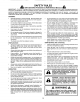
SAFETY RULES Practices for Walk-Behind Safe Operation Mowers IMPORTANT: THIS CUTTING MACHINE IS CAPABLE OF AMPUTATING HANDS At_D FEET AND THROWING FAILURE TO OBSERVE THE FOLLOWING SAFETY INSTRUCTIONS COULD RESULT IN SERIOUS INJURY OBJECTS, OR DEATH. SAFETY STANDARDS REQUIRE OPERATOR PRESENCE CONTROLS TO MINIMIZE THE RISK OF INJURY. YOUR UNIT IS EQUIPPED WITH SUCH CONTROLS. DO NOT ATTEMPT TO DEFEAT THE FUNCTION OF THE OPERATOR PRESENCE CONTROLS UNDER ANY CIRCUMSTANCES.
PRODUCT CONGRATULATIONS on your purchase of a Sears Lawn Mower. It has been designed, engineered and manufactured to give you the best possible dependability and performance SPECIFICATIONS HORSEPOWER: 50 DISPLACEMENT: 8 2 CU. IN. Should you experience any problem you cannot easily remedy, please contact your nearest Sears Authorized Service Center/Department. We have competent, welltrained technicians and the proper tools to service or repair this lawn mower. GASOLINE CAPACITY AND TYPE: t.
TABLE OF CONTENTS SAFETY PRODUCT RULES ............................................................ SPECiFiCATiONS SERVICE AND ADJUSTMENTS ................................ 15 STORAGE ................................................................... 17 TROUBLESHOOTING ................................................. 18 REPAIR PARTS - LAWN P/lOWER ........................ 19-23 REPAIR PARTS - ENGINE .................................... 24-29 PARTS ORDERING/SERVICE ...................................
LAWN MOWER ACCESSO ruES These accessories were available when this lawn mower was produced.. They are also available at most Sears retail outlets and service centers.. Most Sears stores can also order repair parts for you, when you provide the model number of your lawn mower. Some of these accessories may not apply to your lawn mower LAWN MOWER PERFORMANCE L CLIPPING DEFLECTOR FOR REAR DISCHARGE LAWN MOWERS MULCHER KITS.
LY ASSE Read these instructions and this manual in its entirety before you attempt to assemble or operate your new lawn mower_ Your new lawn mower has been assembled at the factory with the exception of those parts left unassembted for' shipping purposes. All parts such as nuts, washers, bolts, etc, necessary to complete the assembly have been placed in the parts bag To ensure safe and proper operation of your tawn mower, all parts and hardware you assemble must be tightened securely..
irll,,_ll_ ASSEMBLY TO ASSEMBLE AND ATTACH GRASS CATCHER (See Figs. 3A thru 4) • _ Insert leg of tubular frame through front opening of grass catcher and thread frame into sewn hem of bag I ] NOTE: Keep bag hem gathered on the straight leg of the tubular frame = When frame comes out the other end of sewn hem, immediately work the end of frame down inside the bag as shown in inset o Slide sewn hem evenly around the tubular frame until both ends of frame are exposed out of the front opening.
OPERATION KNOW YOUR LAWN MOWER READ THIS OWNER'S MANUAL AND SAFETY RULES BEFORE OPERATING YOUR LAWN MOWER. Compare the illustrations with your- lawn mower' to familiarize yourself with the location of various controls and adjustments, Save this manual for future reference, These symbols their meaning. may appear' on your lawn mower' or in literature supplied CAUTION OR WARNING ENGINE ON ENGINE OFF FAST SLOW CHOKE with the product.
OPERATIO The operation of any lawn mower can result in foreign objects thrown into the eyes, which can result in severe eye damage Always wear safety glasses or eye shields while operating your lawn mower or performing any adjustments or repairs We recommend a wide vision safety mask over the spectacles or standard safety glasses..
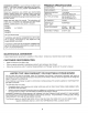
OPERAT'ION ..... BEFORE STARTING i i ENGINE LJ I J lIJ JJl J IIII II I I JJ llll llll LI ENGINE OIL CAP W/DIPSTICK OIL (See Fig. 9) GASOLINE FILLER CAP Your tawn mower is shipped without oil in the engine. = Be sure mower is level and area around oil fill is clean. . Remove engine oil cap w/dipstick and fill to the upper limit mark on dipstick. • Use20ozs of oil. Fortypeandgradeofoiltouse, see "ENGINE" in Customer Responsibilities section of this manual,, . o Pour oil slowly,.
OPERATION MOWING o TiPS Under certain conditions, such as very tall grass, it may be necessary to raise the height of cut to reduce pushing effort and to keep from overloading the engine and leaving clumps of grass clippings • For extremely heavy cutting, reduce the width of cut and raise the rear of the lawn mower housing one (!) wheel adjuster setting higher than the front for better discharge of grass..
, JLJl III CUSTOMER RESPON tLITIES MA,.TE.A.OESC OLE FILL IN DATES REGULAR SERVICE ............. Check for Loose Fasteners Clean/Inspect Grass Catcher .,_'__., ,_'___V!(_E _ _ (If Equipped,) M _"_t¢._.,,"_,"_.,,,7_-_" V' J , Clean Lawn Mower .................... O CIean (Powe[i-,Propel,ted Under Drive,Mowers) Cover ......................
CUSTO ....... ER ESPO nL TUES i;,u, i illt_ ..... LAWN MOWER TIRES o ° CRANKSHAFT SPACER Always observe safety rules when performing any maintenance. BLADE SPACER WASHER Keep tires free of gasoline, oil, or insect control chemicals which can harm rubber_ Avoid stumps, stones, deep ruts, sharp objects and other hazards that may cause tire damage LAWN MOWER Always observe safety rules when performing any maintenance.
CUSTOMER LST ES ESPONSi ii lll,i TO CHANGE ENGINE OIL (See Fig..13) NOTE: Before tipping lawn mower to drain oi!, drain fuel tank by running engine until fuel tank is empty. o Disconnect spark plug wire from spark plug and place wire where it cannot come in contact with spark plug. o Remove engine oil cap; lay aside on a clean surface.. Tip lawn mower on its side and drain oil into a suitable container.. Rock lawn mower back and forth to remove any oil trapped inside of engine..
SE1RV CE AND ADJUST ENTS ,i CAUTION: BEFORE PERFORMING ANY SERVICE OR ADJUSTMENTS: o Release control bar. o Make sure the blade and all moving parts have completely stopped,, o Disconnect spark plug wire from spark plug and place where it cannot come in contact ,,i i,,, ,lllrrj Jlll'l'l': LAWN MOWER TO ADJUST CUTTING CAUTION: The operator presence control bar must pivot freely to permit blade brake engagement when control bar is released.
SERVICE AN[} A DJUSTMENTS CARBURETOR ENGINE ENGINE (See Fig. 20) SPEED The carburetor on your' engine is low emission. The idle mixture screw is fitted with a limiter cap that prevents excessive enrichment of the air-fuel mixture in order to comply with emissions regulations and is not adjustable, Your engine speed has been factory set. Do not attempt to increase engine speed or it may result in personal injury.
,,,11 STORAGE ENGINE Immediately prepare your lawn mower for storage at the end of the season or if the unit wilt not be used for 30 days or moTe., FUEL LAWN MOWER When lawn mower is to be stored for a period of time, clean it thoroughly, remove all dirt, grease, leaves, etc. Store in a clean, dry area. o Clean entire lawn mower (See "CLEANING" in the Customer Responsibilities section of this manual). • Lubricate as shown in the Customer Responsibilities section of this manual.
Lu_,_ L i i ii i i ii ,ll :l TROU LESHOOT! G POmNTS CAUSE PROBLEM Does not start CORRECTION t 2 3 4 Dirty air filter Out of fuel Stale fuel Water in fuel 1 2 3 4 Clean/replace air filter Fill fuel tank, Drain tank and refill with fresh clean fuel Drain fuel tank and carburetorand refill tank with fresh 5 6 7 8 9 Spark ptug wire is disconnected Bad spark plug Loose bIade or broken blade adapter ControI bar in released position Control bar defective 5 6 7 8 9 gasoline Connect Replace Tight
REPAIR PARTS ROTARY LAWN MOWER - - MODEL NO. 917.376370 GEAR CASE ASSEMBLY PART NUMBER 702511 J J 11 7 17 15 17 1o 14 18 10 6 KEY NO. PART NO. 1 2 3 4 6 17490416 137055X004 137053 57072 48373 7 8 9 10 11 77881 137051 t 37074 57079 131484 DESCRIPTION Tapping Screw 1/4-20 x 1-1/4 Engagement Bracket Shifter Seal Gear Case Halves Kit (Includes Key Nos 4, 5, and 7) Bearing Worm Shaft Drive Shaft Hardened Washer CIutch Yoke KEY NO, PART NO.
REPAIR PARTS ROTARY LAWN MOWER MODEL NUMBER 917.376370 8 22 44 3 61 14 12 1_23 56 \ 27 28 3o 2g 39 i2 4 17 o 44 37 52 3O 26 27 29 28 41 32
REPAIR PARTS ROTARY LAWN MOWER MODEL KEY NO.
REPAIR PARTS ROTARY LAWN MOWER MODEL NUMBER 917.376370 1! / 54 18 14 \ 53 10 \ ,, \ 12 25 15 !, 18 10 14 16 \ 41 15 13 12 40
REPAaR PARTS ROTARY LAWN MOWER MODEL KEY NO. 1'O O_ PART NO. 1 3 4 5 6 146323 63601 144929 146527 700875 8 15018? 9 10 11 12 13 14 I5 16 18 25 145212 86960 150340 12000058 137054 88080 88118 67725 701037 152903 DESCRIPTION Control Cable Assembly Locknut #10-24 Pan Head Machine Screw 1/4 x 2.12 V-Belt Carnage Beit t/4-20 x 2 Hubcap Flanged Nut Nylon Bushing Wheel & Tire Assembly E-Ring Pinion Dust Cover Felt Washer Washer 1/2 x 1-1/2 x .134 Selector Knob Drive Cover Decal NUMBER KEY NO.
MODEL .... C.
MODEL NUMBER GXV140A1KY CARBURETOR CONTROL KEY PART NO. NO, DESCRIPTION KEY PART NO. NO.
MODEL FAN COVER NUMBER GXV140A1KY i AIR CLEANER I 5 _6 Q_--i RECOIL 26 STARTER
MODEL NUMBER FAN COVER FLYWHEEL KEY PART NO. NO, DESCRIPTION 1 2 3 4 5 6 7 8 9 10 11 12 13 14 15 16 17 18 19 20 2! 22 23 24 Tube Breather Cotlar, Air Cleaner Air Cleaner Elbow, Complete Cap Assembly, FuelTank Sponge, Fuel Cap Breather Gasket, Fuel Cap Tube, Fuel Tank Fan Cover, Complete Hood, Fan Cover, Black Coil Assembly, Ignition Collar, Roto-Stop Decal, Emblem, 5.0 Decal, Honda Bolt, Flange 6 x 32 Bolt, Stud, Brake Bolt, Stud C Clip B, Cable O-Ring 33.3 x 3.
MODEL NUMBER GXV140A1KY t2 34-0 3_ 32 CYL,NOER HEA01 |o f 8 8 8 8 9 I MUFFLER ! 6 3 28
MODEL NUMBER CRANKSHAFT CYLINDER BARREL KEY PART NO. NO. ! 4722591 2 4224259 3 4459491 4 3307287 5 1662535 6 2794402 7 0452151 8 1452622 9 1825702 10 3337862 1I 3337870 12 3337904 13 1427228 t4 1452846 15 1427244 16 '1452853 17 3337912 t8 1427251 t9 2289643 20 1453000 21 0803619 22 0636076 23 1431246 24 1106764 25 1436583 26 2456697 27 3270246 28 0801043 29 0671628 30 2280006 31 0065185 32 0345900 33 0115527 34 0069310 35 2170793 36 2105815 37 2105849 MUFFLER KEY PART NO. NO.
® OWNE 'S UAL 5.0 HORSEPOWER 22" REAR DUSCHARGE POWER PROPELLED ROTARY LAWN MOWER Each lawn mower has its own model number_ gine has its own model number. MODEL NO. 917.376370 Each em The model number for your lawn mower will be found on a decal attached to the rear of the lawn mower housing.. The model number for your engine will be found on the blower housing of the engine. All parts listed herein may be ordered from any Sears, Roebuck and Co. Service Center!Department and most Retail Stores.
® MODEL NUMBER 917.376370 OWNER'S MANUAL o Assembly o Operation o Customer Responsibilities o Service o Adjustments o Repair Parts Caution: Read and Follow all Safety Rules and Instructions Before Operating This Equipment 153580 Rev_ 1 l 5°6.
SAFETY RULES Practices for Walk-Behind Safe Operation Mowers IMPORTANT: THIS CUTTING MACHINE IS CAPABLE OF AMPUTATING HANDS At_D FEET AND THROWING FAILURE TO OBSERVE THE FOLLOWING SAFETY INSTRUCTIONS COULD RESULT IN SERIOUS INJURY OBJECTS, OR DEATH. SAFETY STANDARDS REQUIRE OPERATOR PRESENCE CONTROLS TO MINIMIZE THE RISK OF INJURY. YOUR UNIT IS EQUIPPED WITH SUCH CONTROLS. DO NOT ATTEMPT TO DEFEAT THE FUNCTION OF THE OPERATOR PRESENCE CONTROLS UNDER ANY CIRCUMSTANCES.
PRODUCT CONGRATULATIONS on your purchase of a Sears Lawn Mower. It has been designed, engineered and manufactured to give you the best possible dependability and performance SPECIFICATIONS HORSEPOWER: 50 DISPLACEMENT: 8 2 CU. IN. Should you experience any problem you cannot easily remedy, please contact your nearest Sears Authorized Service Center/Department. We have competent, welltrained technicians and the proper tools to service or repair this lawn mower. GASOLINE CAPACITY AND TYPE: t.
TABLE OF CONTENTS SAFETY PRODUCT RULES ............................................................ SPECiFiCATiONS SERVICE AND ADJUSTMENTS ................................ 15 STORAGE ................................................................... 17 TROUBLESHOOTING ................................................. 18 REPAIR PARTS - LAWN P/lOWER ........................ 19-23 REPAIR PARTS - ENGINE .................................... 24-29 PARTS ORDERING/SERVICE ...................................
LAWN MOWER ACCESSO ruES These accessories were available when this lawn mower was produced.. They are also available at most Sears retail outlets and service centers.. Most Sears stores can also order repair parts for you, when you provide the model number of your lawn mower. Some of these accessories may not apply to your lawn mower LAWN MOWER PERFORMANCE L CLIPPING DEFLECTOR FOR REAR DISCHARGE LAWN MOWERS MULCHER KITS.
LY ASSE Read these instructions and this manual in its entirety before you attempt to assemble or operate your new lawn mower_ Your new lawn mower has been assembled at the factory with the exception of those parts left unassembted for' shipping purposes. All parts such as nuts, washers, bolts, etc, necessary to complete the assembly have been placed in the parts bag To ensure safe and proper operation of your tawn mower, all parts and hardware you assemble must be tightened securely..
irll,,_ll_ ASSEMBLY TO ASSEMBLE AND ATTACH GRASS CATCHER (See Figs. 3A thru 4) • _ Insert leg of tubular frame through front opening of grass catcher and thread frame into sewn hem of bag I ] NOTE: Keep bag hem gathered on the straight leg of the tubular frame = When frame comes out the other end of sewn hem, immediately work the end of frame down inside the bag as shown in inset o Slide sewn hem evenly around the tubular frame until both ends of frame are exposed out of the front opening.
OPERATION KNOW YOUR LAWN MOWER READ THIS OWNER'S MANUAL AND SAFETY RULES BEFORE OPERATING YOUR LAWN MOWER. Compare the illustrations with your- lawn mower' to familiarize yourself with the location of various controls and adjustments, Save this manual for future reference, These symbols their meaning. may appear' on your lawn mower' or in literature supplied CAUTION OR WARNING ENGINE ON ENGINE OFF FAST SLOW CHOKE with the product.
OPERATIO The operation of any lawn mower can result in foreign objects thrown into the eyes, which can result in severe eye damage Always wear safety glasses or eye shields while operating your lawn mower or performing any adjustments or repairs We recommend a wide vision safety mask over the spectacles or standard safety glasses..
OPERAT'ION ..... BEFORE STARTING i i ENGINE LJ I J lIJ JJl J IIII II I I JJ llll llll LI ENGINE OIL CAP W/DIPSTICK OIL (See Fig. 9) GASOLINE FILLER CAP Your tawn mower is shipped without oil in the engine. = Be sure mower is level and area around oil fill is clean. . Remove engine oil cap w/dipstick and fill to the upper limit mark on dipstick. • Use20ozs of oil. Fortypeandgradeofoiltouse, see "ENGINE" in Customer Responsibilities section of this manual,, . o Pour oil slowly,.
OPERATION MOWING o TiPS Under certain conditions, such as very tall grass, it may be necessary to raise the height of cut to reduce pushing effort and to keep from overloading the engine and leaving clumps of grass clippings • For extremely heavy cutting, reduce the width of cut and raise the rear of the lawn mower housing one (!) wheel adjuster setting higher than the front for better discharge of grass..
, JLJl III CUSTOMER RESPON tLITIES MA,.TE.A.OESC OLE FILL IN DATES REGULAR SERVICE ............. Check for Loose Fasteners Clean/Inspect Grass Catcher .,_'__., ,_'___V!(_E _ _ (If Equipped,) M _"_t¢._.,,"_,"_.,,,7_-_" V' J , Clean Lawn Mower .................... O CIean (Powe[i-,Propel,ted Under Drive,Mowers) Cover ......................
CUSTO ....... ER ESPO nL TUES i;,u, i illt_ ..... LAWN MOWER TIRES o ° CRANKSHAFT SPACER Always observe safety rules when performing any maintenance. BLADE SPACER WASHER Keep tires free of gasoline, oil, or insect control chemicals which can harm rubber_ Avoid stumps, stones, deep ruts, sharp objects and other hazards that may cause tire damage LAWN MOWER Always observe safety rules when performing any maintenance.
CUSTOMER LST ES ESPONSi ii lll,i TO CHANGE ENGINE OIL (See Fig..13) NOTE: Before tipping lawn mower to drain oi!, drain fuel tank by running engine until fuel tank is empty. o Disconnect spark plug wire from spark plug and place wire where it cannot come in contact with spark plug. o Remove engine oil cap; lay aside on a clean surface.. Tip lawn mower on its side and drain oil into a suitable container.. Rock lawn mower back and forth to remove any oil trapped inside of engine..
SE1RV CE AND ADJUST ENTS ,i CAUTION: BEFORE PERFORMING ANY SERVICE OR ADJUSTMENTS: o Release control bar. o Make sure the blade and all moving parts have completely stopped,, o Disconnect spark plug wire from spark plug and place where it cannot come in contact ,,i i,,, ,lllrrj Jlll'l'l': LAWN MOWER TO ADJUST CUTTING CAUTION: The operator presence control bar must pivot freely to permit blade brake engagement when control bar is released.
SERVICE AN[} A DJUSTMENTS CARBURETOR ENGINE ENGINE (See Fig. 20) SPEED The carburetor on your' engine is low emission. The idle mixture screw is fitted with a limiter cap that prevents excessive enrichment of the air-fuel mixture in order to comply with emissions regulations and is not adjustable, Your engine speed has been factory set. Do not attempt to increase engine speed or it may result in personal injury.
,,,11 STORAGE ENGINE Immediately prepare your lawn mower for storage at the end of the season or if the unit wilt not be used for 30 days or moTe., FUEL LAWN MOWER When lawn mower is to be stored for a period of time, clean it thoroughly, remove all dirt, grease, leaves, etc. Store in a clean, dry area. o Clean entire lawn mower (See "CLEANING" in the Customer Responsibilities section of this manual). • Lubricate as shown in the Customer Responsibilities section of this manual.
Lu_,_ L i i ii i i ii ,ll :l TROU LESHOOT! G POmNTS CAUSE PROBLEM Does not start CORRECTION t 2 3 4 Dirty air filter Out of fuel Stale fuel Water in fuel 1 2 3 4 Clean/replace air filter Fill fuel tank, Drain tank and refill with fresh clean fuel Drain fuel tank and carburetorand refill tank with fresh 5 6 7 8 9 Spark ptug wire is disconnected Bad spark plug Loose bIade or broken blade adapter ControI bar in released position Control bar defective 5 6 7 8 9 gasoline Connect Replace Tight
REPAIR PARTS ROTARY LAWN MOWER - - MODEL NO. 917.376370 GEAR CASE ASSEMBLY PART NUMBER 702511 J J 11 7 17 15 17 1o 14 18 10 6 KEY NO. PART NO. 1 2 3 4 6 17490416 137055X004 137053 57072 48373 7 8 9 10 11 77881 137051 t 37074 57079 131484 DESCRIPTION Tapping Screw 1/4-20 x 1-1/4 Engagement Bracket Shifter Seal Gear Case Halves Kit (Includes Key Nos 4, 5, and 7) Bearing Worm Shaft Drive Shaft Hardened Washer CIutch Yoke KEY NO, PART NO.
REPAIR PARTS ROTARY LAWN MOWER MODEL NUMBER 917.376370 8 22 44 3 61 14 12 1_23 56 \ 27 28 3o 2g 39 i2 4 17 o 44 37 52 3O 26 27 29 28 41 32
REPAIR PARTS ROTARY LAWN MOWER MODEL KEY NO.
REPAIR PARTS ROTARY LAWN MOWER MODEL NUMBER 917.376370 1! / 54 18 14 \ 53 10 \ ,, \ 12 25 15 !, 18 10 14 16 \ 41 15 13 12 40
REPAaR PARTS ROTARY LAWN MOWER MODEL KEY NO. 1'O O_ PART NO. 1 3 4 5 6 146323 63601 144929 146527 700875 8 15018? 9 10 11 12 13 14 I5 16 18 25 145212 86960 150340 12000058 137054 88080 88118 67725 701037 152903 DESCRIPTION Control Cable Assembly Locknut #10-24 Pan Head Machine Screw 1/4 x 2.12 V-Belt Carnage Beit t/4-20 x 2 Hubcap Flanged Nut Nylon Bushing Wheel & Tire Assembly E-Ring Pinion Dust Cover Felt Washer Washer 1/2 x 1-1/2 x .134 Selector Knob Drive Cover Decal NUMBER KEY NO.
MODEL .... C.
MODEL NUMBER GXV140A1KY CARBURETOR CONTROL KEY PART NO. NO, DESCRIPTION KEY PART NO. NO.
MODEL FAN COVER NUMBER GXV140A1KY i AIR CLEANER I 5 _6 Q_--i RECOIL 26 STARTER
MODEL NUMBER FAN COVER FLYWHEEL KEY PART NO. NO, DESCRIPTION 1 2 3 4 5 6 7 8 9 10 11 12 13 14 15 16 17 18 19 20 2! 22 23 24 Tube Breather Cotlar, Air Cleaner Air Cleaner Elbow, Complete Cap Assembly, FuelTank Sponge, Fuel Cap Breather Gasket, Fuel Cap Tube, Fuel Tank Fan Cover, Complete Hood, Fan Cover, Black Coil Assembly, Ignition Collar, Roto-Stop Decal, Emblem, 5.0 Decal, Honda Bolt, Flange 6 x 32 Bolt, Stud, Brake Bolt, Stud C Clip B, Cable O-Ring 33.3 x 3.
MODEL NUMBER GXV140A1KY t2 34-0 3_ 32 CYL,NOER HEA01 |o f 8 8 8 8 9 I MUFFLER ! 6 3 28
MODEL NUMBER CRANKSHAFT CYLINDER BARREL KEY PART NO. NO. ! 4722591 2 4224259 3 4459491 4 3307287 5 1662535 6 2794402 7 0452151 8 1452622 9 1825702 10 3337862 1I 3337870 12 3337904 13 1427228 t4 1452846 15 1427244 16 '1452853 17 3337912 t8 1427251 t9 2289643 20 1453000 21 0803619 22 0636076 23 1431246 24 1106764 25 1436583 26 2456697 27 3270246 28 0801043 29 0671628 30 2280006 31 0065185 32 0345900 33 0115527 34 0069310 35 2170793 36 2105815 37 2105849 MUFFLER KEY PART NO. NO.
® OWNE 'S UAL 5.0 HORSEPOWER 22" REAR DUSCHARGE POWER PROPELLED ROTARY LAWN MOWER Each lawn mower has its own model number_ gine has its own model number. MODEL NO. 917.376370 Each em The model number for your lawn mower will be found on a decal attached to the rear of the lawn mower housing.. The model number for your engine will be found on the blower housing of the engine. All parts listed herein may be ordered from any Sears, Roebuck and Co. Service Center!Department and most Retail Stores.