I CRAFTSMAN1 Oil Lubricated Two Stage Stationary AIR COMPRESSOR Model No. 919.176502 • Safety Guidelines • Assembly • • Operation Maintenance • Service • Troubleshooting • Repair and Adjustments Parts CAUTION: Read the Safety Guidelines and All Instructions Carefully Before Operating. Sears, D26056 Rev. 1 Roebuck and Co., Hoffman Estates, IL 60179 U.S.A. Visit our Craftsman website: www.sears.
Inf:_ :] q =1[o]_ [o_o]_hnl=1_i __] WARRANTY ................................................ 2 SPECIFICATION CHART ..................................... SAFETY GUIDELINES ...................................... GLOSSARY ................................................ ACCESSORIES ............................................. 3 3-8 9 9 DUTY CYCLE .............................................. ASSEMBLY ............................................... INSTALLATION ..........................................
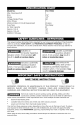
[,.__o,]2i][o]_] [o,]-"P'_,_ :_nnl Model N o. 919-176502 Max. Developed Bore Stroke Voltage-Single Motor Phase HP 5 3.54" 1.97" Phase 240 1 Minimum Branch Circuit Requirement Fuse Type Air Tank Capacity Approx. Cut-In Approx. Cut-out SCFM @ 100 psig 20 amps Time Delay 60 140 175 12.0 [-'f_'1al=lli'd [=_llJI m]=1mlI_I =[,.1..I m]=1alI _I InII[o]][[,1 This manual contains information that is important for you to know and understand.
Save these instructions Improper operation or maintenance of this product could result in serious injury and property damage. Read and understand all warnings and operation instructions before using this equipment. : V:YJ:I;] m] WARNING: Risk of explosion or fire How To Prevent It What Could Happen It is normal for electrical contacts within the motor and pressure switch to spark.
: V;YJ;I;1m_ WARNING: Risk of Bursting I_1 Air Tank: The following conditions could lead to a weakening in a violent tank explosion and could cause property damage How To Prevent It What Could Happen Failure to properly drain condensed water from tank, causing rust and thinning of the steel tank. 2. 3. of the tank, and result or serious injury. Drain tank daily or after each use. If tank develops a leak, replace it immediately with a new tank or replace the entire compressor.
I: V.._:l I'lm] WARNING: Risk of Electrical Shock WHAT CAN HAPPEN HOW TO PREVENT IT Your air compressor is powered by electricity. Like any other electrically powered device, If it is not used properly it may cause electric shock. Never operate the compressor outdoors when it is raining or in wet conditions. Repairs attempted by unqualified personnel can result in serious injury or death by electrocution.
I: F.._I.lI'lm] WARNING: RISK OF BURNS WHAT CAN HAPPEN HOW TO PREVENT IT Touching exposed metal such as the compressor head or outlet tubes, can result in serious burns. Never touch any exposed metal parts on compressor during or immediately after operation. Compressor will remain hot for several minutes after operation. Do not reach around protective shrouds or attempt maintenance until unit has been allowed to cool. I: F.._I.
I: V;YJ;I;1m] WARNING: RISK OF UNSAFE OPERATION WHAT CAN HAPPEN Unsafe operation of your air compressor could lead to serious injury or death to you or others, D26056 HOW TO PREVENT IT Review and understand all instructions and warnings in this manual. Become familiar with the operation and controls of the air compressor. Keep operating area clear of all persons, pets, and obstacles. Keep children away from the air compressor at all times.
Cut-Out Pressure: When an air compressor is turned on and begins to run, air pressure in the air tank begins to build. It builds to a certain high pressure before the motor automatically shuts off - protecting your air tank from pressure higher than its capacity. The high pressure at which the motor shuts off is called "cut-out" pressure. Branch Circuit: Circuit carrying electricity from electrical panel to outlet.
I_..'.,_".] =iLv_ I :] i_"d Contents 1 1 1 1 4 - of Carton Multi-Viscosity motor oils, like 10W 30, should not be used in an air compressor. They leave carbon deposits on critical components, thus reducing performance and compressor life. Use air compressor oil onlv. 1. Remove the oil drain plug (B) and washer (C). Air Compressor Parts bag containing: Operator's Manual Parts Manual 5/8" Washers Tools Required for Assembly 1 - 9/16" socket or open end wrench 1 - electric drill Unpacking 1.
II__"hf;_ mlW:'Inl[o_ HOW TO SET UP YOUR Location UNIT Place the air compressor solid, level surface. 2. Mark the surface using the holes in the air compressor feet as a template. Drill holes in the surface for the concrete anchors. Install concrete anchors. of the Air Compressor • Locate the air compressor in a clean, dry, and well ventilated area. • Locate the air compressor at least 12" away from the wall or other obstructions that will interfere with the flow of air.
Wiring Instructions _ RISK OF ELECTRICAL SHOCK. Improper electrical grounding can result in electrical shock. The wiring should be done by a qualified electrician to comply with national and local electrical codes. A qualified electrician needs to knows the following before wiring: 1. 2. The amperage rating of the electrical box should be adequate. Refer to the product specifications, found in the front of this manual, for this information.
AIR PLOW _ FEEDER WITH LINES SLOPE AIR PLOW ___A_R MA_N DISTRIBUTION PLOW A_R LINES Slope pipe in diroction of _ir flow.
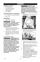
Know Your Air Compressor READ THIS OWNER'S MANUAL AND SAFETY RULES BEFORE OPERATING YOUR UNIT. Compare the illustrations with your unit to familiarize yourself with the location of various controls and adjustments. Save this manual for future reference. Description of Operation Become familiar with these controls before operating the unit. Tank Pressure Gauge: The tank pressure gauge indicates the reserve air pressure in the tank. Globe Valve (sold separately): Opens and closes air discharge valve.
Air Compressor Pump (not shown): Compresses air into the air tank. Working air is not available until the compressor has raised the air tank pressure above that required at the air outlet. Air Intake Filter (not shown) This filter is designed to clean air coming into the pump. This filter must always be clean and ventilation openings free from obstructions. See "Maintenance". Check Valve: When the air compressor is operating, the check valve is "open", allowing compressed air to enter the air tank.
5. Run the minutes. valve is minimal tank. 6. Check all air line fittings and connections/piping for air leaks by applying a soap solution. Correct if necessary. NOTE: Minor leaks can cause the air compressor to overwork, resulting in premature breakdown or inadequate performance. 7. 8. compressor for 20 Make sure the globe open and there is air pressure build-up in Check for excessive vibration. Readjust or shim air compressor feet, if necessary. After 20 minutes, close the globe valve.
Customer Responsibilities Before Every Every Every Every each 8 40 100 160 use hours hours hours hours Check Safety Valve Every 500 Yearly hours • Drain Tank Check Oil • • Change Oil Unusual Noise and/or Vibration 0 2 02 • Air Filter O1 Drive Belt-Condition • Motor Pulley/Flywheel alignment • Air compressor pump intake and exhaust valves Inspect air lines and fittings for leaks • • Head Bolts - Check the torques of the head bolts after the first five hours of operation.
To Drain Tank NOTE: Operation of the air compressor will cause condensation to build up in the air tank. Always drain tank on a washable surface or in a suitable container to prevent damaging or staining surfaces. 1. Set the On/Auto/Off lever to "OFF". 2. 3. 4. 5. 6. Close the globe valve. Remove the air tool or accessory. Open the globe valve and allow the air to slowly bleed from the air tank until tank pressure is approximately 20 psi. Close the globe valve.
Air Filter - Inspection Replacement and Hot surfaces. Risk of burn. Compressor heads are exposed when filter cover is removed. Allow compressor to cool prior to servicing. A dirty air filter will not allow the compressor to operate at full capacity. Keep the air filter clean at all times. 1. Remove the air filter cover. 2. Remove the air filter from filter cover. 5. Remove the belt and replace with a new one. 6. See the "Adjust Belt Tension" before tightening motor mounting screws.
7. Motor Pulley/Flywheel Alignment NOTE: Once the motor pulley has been moved from its factory set location, the grooves of the flywheel and pulley must be aligned to within 1/16" to prevent excessive belt wear. The air compressor flywheel and motor pulley must be in-line (in the same plane) within 1/16" to assure belt retention within flywheel belt grooves. To check alignment, perform the following steps: 1.
Unit cycles automatically when power is on. When doing Maintenance, you may be exposed to voltage sources, compressed air or moving parts. Personal injuries can occur. Before performing any Maintenance or repair, unplug the compressor and bleed off all air pressure. 8, Unscrew the check valve (turn counterclockwise) using a 7/8" open end wrench. Note the orientation for reassembly. 6, Using a screwdriver, carefully push the valve disc up and down.
Motor 4. This motor has a manual thermal overload protector. If the motor overheats for any reason, the overload protector will shut off the motor. The motor must be allowed to cool down before restarting. To restart: IMPORTANT: If the overload protector shuts the motor off frequently, check for a possible voltage problem. Low voltage can also be suspected when: 1. 1. The motor does not get up to full power or speed. 2.
bd-'_o_!_oIo_ Performing repairs may expose voltage sources, moving parts or compressed air sources, moving parts or compressd air sources. Personal injury may occur. Prior to attempting any repairs, unplug the air compressor and bleed off all air tank air pressure. PROBLEM Excessive tank pressure (safety valv@ pops off. CAUSE CORRECTION Pressure switch does not shut off motor when compressor reaches "cutout" pressure. Pressure switch "cut-out" too high.
PROBLEM CAUSE CORRECTION If there is an excessive amount of pressure drop when the accessory is used, adjust the regulator as instructed in the Operation section. NOTE: Adjust the regulated pressure under flow conditions (while accesory is being used). Pressure reading on the regulated pressure gauge (if equipped) drops when an accessory is used. It is normal for "some" pressure drop to occur. Air leak from safety valve. Possible defect in safety valve.
PROBLEM Motor will not run. CAUSE Motor overload protection switch has tripped CORRECTION Let motor cool off and overload switch will automatically reset. Tank pressure exceeds _ressure switch "cut-in" %essure. Motor will start automatically when tank pressure drops below "cut-in" pressure of pressure switch. Check valve stuck open. Remove and clean, or replace. Loose electrical connections. Check wiring connection inside pressure switch and terminal box area.
PROBLEM CORRECTION CAUSE Knocking Noise. Possible defect in safety Excessive belt wear. Squealing sound. valve. Operate safety valve manually by pulling on ring. If valve still leaks, it should be replaced. Defective check valve. Remove and clean, or replace. Loose pulley. Tighten pulley set screw, 145-165 in.-Ibs. Loose flywheel. Tighten flywheel screw 33-37 ft.-Ibs. Compressor mounting screws loose. Tighten mounting 20-25 ft.-Ibs. Loose belt.
_ENG D26056
r:l I ;! [o.
KEY NO.
19 18 14 15 1 11 D26056 30-ENG
It2_'_ _i i-1 I]_tii KEY NO.
GARANTIA .......................................................... CUADRO DE ESPECIFICACIONES DEFINIClONES DE NORMAS IMPORTANTES INSTRUCCIONES GLOSARIO 28 ...................................... DE SEGURIDAD 29 ............................. DE SEGURIDAD 29 ...................... 29-34 .......................................................... ACCESORIOS ClCLO DE SERVIClO ENSAMBLADO INSTALAClC)N OPERACION 35 .................................................. 35 .......................
[_uY__1 D]:To]ID]=II =[.'-]-j =[_]I;d[#'__I_][o]_I=[.'-] Modelo N ° Max. HP desarrollado 919-176502 5 Di_metro interior Carrera Tensi6n monof_sica Fase del Motor 3,54 po 1,97 po 240/60 1 Circuito minimo requerido Tipo de Fusible Capacidad de aire en el tanque Presi6n de corte de entrada Presi0n de corte de salida 20A Acci6n Retardada 60 Galones (113,6 litros) 140 175 SCFM @ 100 psig 12,0 Calibre de libra por pulgada cuadrada I"] =1alI _I [o,][o]]_]#[.
GUARDE ESTAS INSTRUCCIONES LA OPERACI(_N O EL MANTENIMIENTO INADECUADOS DE ESTE PRODUCTO PODRIAN OCASIONAR SERIAS LESIONES Y DANOS A LA PROPIEDAD. LEA Y COMPRENDA TODAS LAS ADVERTENCIAS E INSTRUCCIONES DE FUNCIONAMIENTO ANTES DE UTILIZAR ESTE EQUIPO. I'.
I'.,1_ ! [_-"_*] ADVERTENCIA: TANQUE DE AIRE: LAS RIESGO SIGUIENTES DEBILITAMIENTO DEL A LA PROPIEDAD O SERIAS LESlONES. _QUI_ PUEDE TANQUE, DE EXPLOSION I_l CONDICIONES Y DETERMINAR PODRJAN, SU EXPLOSION OCURRIR? _,C6MO CAUSAR VIOLENTA, EL DAI_IOS PREVENIRLO? 1. Drenaje inadecuado del agua condensada en el tanque, siendo la causa del 6xido que reduce el espesor del tanque de acero. Drene el tanque diariamente o despu_s de cada uso.
I:,,,1 _1! [,_ --[e] ADVERTENCIA: _QUE PUEDE RIESGO DE DESCARGA ELleCTRICA OCURRIR? _,C6MO PREVENIRLO? Su compresor de aire est& accionado per electricidad. Cemo cualquier otto dispositivo el6ctrice impulsado el_ctricamente, si no se Io utiliza adecuadamente, podria causarle una descarga el_ctrica. Jam&s opere el compresor a la intemperie cuando est& IIoviendo o en condiciones de humedad.
I",,,,1 =1! [,_ --[e] ADVERTENCIA: _,QU# PUEDE RIESGO DE QUEMADURAS OCURRIR? _,C6MO Tocar el metal expueeto tal como el cabezal del compresor o los tubos de salida del escape, puede ocaeienarle eeriae quemadurae. PREVENIRLO? Jam_s toque partes de metal expueetas en el compresor durante o inmediatamente despu_s de la operaci6n, el eempresor permanecer;_ ealiente per varios minutos luego de la operaci6n.
I ",,] ::1! [€t:[,] ADVERTENCIA: RIESGO DE OPERACION _,QUE PUEDE INSEGURA OCURRIR? La operacion insegura de su compresor de aire podria ocasionarle serias lesiones o la muerte a usted u otros. },COMO PREVENIRLO? Revise y comprenda todas las instrucciones y advertencias contenidas en este manual. Familiaricese con los m_todos control del compresor de aire. de operaci6n Mantenga libre la zona de operaciones de persona alguna, animales domesticos y obst&culos.
Presi6n Familiaricese con los siguientes t@minos, antes de operar la unidad: CFM: (Cubic feet per minute) Pies c0bicos por minuto. SCFM: (Stardard cubic feet per minute) Pies c0bicos estandar por minuto; una unidad de medida que permite medir la cantidad de entrega de aire. PSIG: (Pounds Per Square Inch Gauge) Presi6n manometrica efectiva en libras por pulgada cuadrada; una medida de la entrega de aire.
Contenido , ,_o de la Caja 1 - Compresor 1 - Bolsa de piezas conteniendo de aire 1 - Manual del operador 1 - Manual de piezas 4 - Arandelas de 5/8" necesarias para _ Nosedebenusar aceites de viscosidad mt_ltiple como 10W30 en ningtin compresor de aire. Estos aceites dejan depbsitos de carbono en componentes criticos, reduciendo el rendimiento y la vida titil del compresor. Sblo usar aceite para compresor de aire. Io siguiente: Herramientas ensamble _ 1.
Ubicacibn del compresor 1. de aire • Instale el compresor de aire en una zona limpia, seca y bien ventilada. • Instale el compresor 2. de aire a una distancia no menor de 30 cm (12") de la pared u otras obstrucciones que pudiesen interferir con el flujo del aire. • Instale el compresor de aire Io mas cerca posible del sitio de alimentaci6n electric& a fin de evitar 3. 4. 5. el uso de largas extensiones de cableado electrico.
Instrucciones el_ctrica para Sistema la conexi6n , RIESGO DE ELECTROCUCION. Una Antes de efectuar las conexiones, un electricista calificado debe conocer Io compresor Utilice caPio de la misma medida que el de la salida del tanque de aire. Una ca_erfa demasiado angosta restringira el paso del aire. • Si la ca_erla tiene mas de 30 m (100 pies) de Iongitud, utilice la medida inmediata superior.
PENDIENFE DE LA DE ALIMENTAOIQN FU£ERiA ()ON FLUJO ) FILTRO _ FL[XIBLE U)BRICADOR ?) ACOPLAMIENT VALVULA COLUMNA ESFERICA DE DESECHO$ ©OMPRESK)N DE AIRE SlSTEMA TiP,CO DE DISTRISUCI6N DE AiR == VALVULA-GRIFO 43-SP DE PURGA D26056
Conozca su compresor de aire LEA ESTE MANUAL DEL PROPIETARIO Y SUS NORMAS DE SEGURIDAD ANTES DE OPERAR LA UNIDAD. Compare las ilustraciones contra su unidad a fin de familiarizarse con la ubicaci6n de los distintos controles y regulaciones. Conserve este manual para referencias futuras. Descripci6n Familiarfcese de operaciones Man6metro de la presi6n del tanque: El man6metro que controla la presi6n del tanque indica la reserva de presi6n del tanque de aire.
C6mo utilizar su unidad Valvula reguladora: Cuando el compresor de aire se encuentra funcionando, la v_lvula reguladora esta "abier_a", permitiendo la entrada del aire comprimido al tanque de aire. Cuando el nivel de presi6n del tanque alcanza el punto de "corte", la valvula reguladora "se cierra", reteniendo la presi6n del aire dentro del tanque. C6mo detenerla: 1. Coloque la posici6n de la Ilave interruptora On/Auto/Off en la posici6n "OFF".
7. Verifique la existencia de vibraci6n excesiva. Reajuste o acute el pie del compresor, si ello fuera necesario. 8. Luego de 20 minutos, cierre la valvula de asiento. El aire recibido elevara la presidn hasta el punto de "presidn de corte", y ello hara detener al motor. El compresor usado. Como poner en marcha 1. valor de presi6n "de corte" del tanque. 2. estara ahora listo para ser Coloque el interruptor On/Auto/Off en la posicidn "OFF" y cierre el regulador de aire. 2.
hV_ I:] _/II :1_I I M 1:1_/ I[e] ResponsabUidades del cliente I Antes de cada USO Verifique la v_lvula de seguridad ICada Cada 8 40 horas horas Cada 160 horas Cada 500 Anualmente horas • Drenaje del tanque • Verifique el aceite • Cambio de Cada 100 horas aceite •2 •2 Ruido inusual y/o vibraci6n • Filtro de aire •_ Estado de la correa • Alineado de la polea/volante del motor • V_.
Cbmo drenar el tanque NOTA: La operaci6n del compresor de aire causa condensacion que se acumula dentro del tanque de aire. Drene siempre el tanque sobre una superficie lavable o dentro de un contenedor apropiado, con el objeto de prevenir dafios o el manchado de superficies. 1. 2. Coloque la palanca On/Auto/Off la posici6n "OFF". Cierre la valvula de asiento. en 3. Remueva la herramienta o el accesorio. neumAtica 4.
Filtro de Aire - Inspeccibn y reemplazo _ 5. Retire la correa y reempl_cela una nueva. 6. Vea "Regulaci6n de la tensi6n de la correa" antes de ajustar los tornillos montantes del motor. Superficies calientes. Riesgo de quemaduras. Las cabezas del compresor estan expuestas cuando se retira la cubierta del filtro. Deje enfriar al compresor antes de darle servicio. Regulaci6n 1. Retire la tapa del filtro de aire. Extraiga el filtro de aire de la cubierta. 1.
Polea y volante 8. - Alineaci6n NOTA:Una vez que la polea del motor ha eido movida, punto de su instalaci6n original de fabrica, las ranurae del volante y la polea deben alinearse dentro un rango de variaci6n de 1/16" (1,6 mm), para prevenir un excesivo desgaste de la correa. El volante del compresor de aire y la polea del motor deben estar en linea (en el mismo piano) dentro de una variaci6n de 1/16" (1,6 mm), para asegurar la retenci6n de la correa dentro de las ranuras del volante.
, ,_ o _ Launidadcicla automaticamente Desenrosque la vMvula de retenci6n girAndola hacia la izquierda usando una Ilave de boca de 7/8" (22 mm). Tome nota de la orientaci6n para volverla a ensamblar. en cuanto la energia eldctrica es conectada. AI efectuar el mantenimiento, usted quedara expuesto a tensibn viva, aire comprimido o partes en movimiento. Debido a tales circunstancias, podrian ocurrirle lesiones personales.
Motor NOTA: Si el protector de sobrecarga apaga el motor con mucha frecuencia, verifique si hay algt_n posible Este motor tiene un protector manual de sobrecarga termica. Si el motor se sobrecalienta por cualquier motivo, el protector de sobrecarga apaga el motor. Debe permitirse que el motor enfrie antes de volverlo a arrancar de la siguiente forma: 1. 2. 3. 4. Mover la palanquita de On/Auto/Off la posici6n de Off. Permitir que el motor se enfrie. problema de voltaje.
[et!#;Yl.]=ll.]V;_'_e_ .]=1-3;_e]lm=lLv_V;_. -] El desarrollo de reparaciones puede exponer a sitios con corriente viva, partes en movimiento o fuentes de aire comprimido que podrian ocasionar lesiones personales. Antes de intentar reparaci6n alguna, desenchufe el compresor de aire y purgue toda la presi6n de aire del tanque. PROBLEMA Presi6n excesiva CORRECClON CAUSA El interruptor de presi6n no interrumpe al motor cuando el compresor alcanza la presi6n "de corte".
PROBLEMA La lectura de la presi6n sobre el man6metro CORRECClON CAUSA Es normal que ocurra algt3n descenso en la presi6n. regulado (si viene equipado con 61) desciende al utilizar un accesorio. P@dida de aire en la valvula de Operaci6n. NOTA: Ajuste la presi6n regulada bajo condiciones de flujo (mientras se este usando el accesorio). Probable defecto en la valvula de seguridad. seguridad. El compresor no esta suministrando suficiente cantidad de aire para operar los accesorios.
PROBLEMA El motor no funciona. CORRECClON CAUSA El interrupter de protecci6n obrecarga del motor se ha abier_o. des Deje enfriar el motor y el interruptor de sobrecarga se reajustarA automAticamente. La presi6n del tanque excede la presi6n de "corte mAximo" del interruptor de presi6n. El motor arrancarA automAticamente La vAIvula de retenci6n se ha Retire y limpie, o reemplace. cuando la presi6n del tanque caiga por debajo de la presi6n de corte maxima del interruptor de presi6n. quedado abierta.
PROBLEMA Golpeteo. CORRECClON CAUSA Posible defecto en la valvula de seguridad. Opere la valvula de seguridad manualmente tirando de su anillo. Si la valvula aun pierde, debera ser reemplazada. Posible defecto en la valvula Extraiga y limpie o reemplace. de seguridad. Polea floja. Ajuste el tornillo de la polea a, 33-37 pulg.-Ibs. Volante flojo. Ajuste el tornillo del volante, 20-25 pies-lbs. Tornillos montantes compresor del Ajustar los tornillos de montaje a, 20-25 pies-lbs. flojos.
-SP D26056
D26056 58-SP
-SP D26056
Your Home For repair - in your home - of all major brand appliances, lawn and garden equipment, or heating and cooling systems, no matter who made it, no matter who sold it! For the replacement parts, accessories and owner's manuals that you need to do-it-yourself. For Sears professional installation of home appliances and items like garage door openers and water heaters. 1-800-4-MY-HOME ® (1-800-469-4663) www.sears.com Anytime, day or night (U.S.A. and Canada) www.sears.