Owner's Manual 5.5 Horsepower 2400 PSI 2.2 GPM PRESSURE WASHER Model No. 919.769060 • Safety Guidelines • Assembly • Operation • Maintenance • Storage • Troubleshooting • Repair • Espa_ol Parts CAUTION: Read the Safety Guidelines and All Instructions Carefully Before Operating. Sears, D25852 Rev. 2 Roebuck and Co., Hoffman Estates, IL 60170 U.S.A. visit our craftsman website: www.sears.
Inf:_ :] q =1[o]_ [o_o]_hnl=1_i __] WARRANTY ................................................ SPECIFICATION CHART ..................................... SAFETY GUIDELINES- DEFINITIONS ........................... IMPORTANT SAFETY INSTRUCTIONS ........................ BOX CONTENTS ............................................ ASSEMBLY ............................................... OPERATION ............................................ MAINTENANCE ......................................... STORAGE ..............
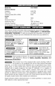
_'_I;_[o,][_o]_l [o_-"E_-'_n nl Model No. Pressure Washer Pressure Flow Rate 919-769060 Cleaning Units (PSI x GPM) Engine RPM 5280 Rated Horsepower Spark Plug Gap Gasoline Capacity Oil .58 quarts ( .55 liters) capacity 5.5 .030" (0.76ram) .29 gallons (1.1 liters) SAE 30 weight 2400 PSI 2.2 GPM 3600 This manual contains information that is important for you to know and understand. This information relates to protecting YOUR SAFETY and PREVENTING EQUIPMENT PROBLEMS.
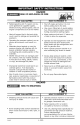
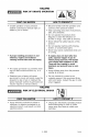
HAZARD RISK OF EXPLOSION OR FIRE WHAT CAN HAPPEN HOW TO PREVENT • Spilled gasoline and it's vapors can become ignited from cigarette sparks, electrical arcing, exhaust gases, and hot engine components such as the muffler. • Shut off engine and allow it to cool before adding fuel to the tank. • Heat will expand fuel in the tank which could result in spillage and possible fire explosion. • Keep maximum fuel level 1/2" below top of tank to allow for expansion.
HAZARD RISK OF UNSAFE OPERATION WHAT CAN HAPPEN HOW TO PREVENT • Unsafe operation of your pressure washer could lead to serious injury or death to you or others. IT • Become familiar with the operation and controls of the pressure washer. • Keep operating area clear of all persons, pets, and obstacles. Do not operate the product when fatigued or under the influence of alcohol or drugs. Stay alert at all times. Never defeat the safety features of this product.
HAZARD RISK TO FLUID INJECTION WHAT CAN HAPPEN HOW TO PREVENT • Your washer operates at fluid pressures and velocities high enough to penetrate human and animal flesh, which could result in amputation or other serious injury. Leaks caused by loose fittings or worn or damaged hoses can result in injection injuries. DO NOT TREAT FLUID INJECTION AS A SIMPLE CUT! See a physician immediately! IT • Never place hands in front of nozzle. • Direct spray away from self and others.
HAZARD RISK OF HOT SURFACES WHAT CAN HAPPEN I JI HOW TO PREVENT • Contact with hot surfaces, such as engines exhaust components, could result in serious burn. IT • During operation, touch only the control surfaces of the pressure washer. Keep children away from the pressure washer at all times. They may not be able to recognize the hazards of this product.
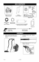
Knobs Part No. _'_ English/ Spanish Operator's Manual Engine Frame and Wheel Assembly _ Saddle Bolts Part No. D23196 TL_ Nozzle Cleaning _--Kit Allen Wrench Part No, 16797 Cleaning Tool Part No. NCT001 Handle Part No. D22302 Bagged Parts 0 High Pressure Hose Part No. D22166 16471 _-_ Chemical Hose Part No. HI40 Accessories Panel Part No, D25081 with Screws Part No. D22901 Engine Oil .... f_ 1. D25852 _ ................................................ _1_ i Multi-Beg Wand Part No.
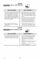
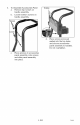
5, Screws To Assemble Accessories Panel a. Remove top screws on handle assembly. b. Loosen bottom screws on handle assembly. r Remove d, C. Place screws (removed earlier) into the top holes and secure accessories panel assembly to handles. Do not overtighten. Place grooves in accessories panel assembly onto screws and slide panel assembly into place.
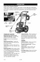
Know Your Pressure Washer READ THIS OWNER'S MANUAL AND SAFETY RULES BEFORE OPERATING YOUR UNIT. Compare the illustrations with your unit to familiarize yourself with the location of various controls and adjustments. Save this manual for future reference. Chemical High Pressure Air Filter Lever Multi-Peg Wand High Pump PRESSURE Chemical Hose: Allows cleaners or cleaning solvents to be mixed with the pressurized water stream.
HOW TO USE PRESSURE WASHER TERMINOLOGY IMPORTANT: Read and understand how to use the pressure washer before operating. NOTE: Become familiar with this terminology before operating. PSI: Pounds per Square Inch. The unit of measure for water pressure. Also used for air pressure, hydraulic pressure, etc. GPM: Gallons Per Minute. The unit of measure for the flow rate of water through the pressure washer. CU: Cleaning Units. GPM multiplied by PSI.
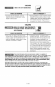
The nozzle at the end of the multi-reg wand can be rotated to change the high pressure spray pattern from a narrow jet to a 40 ° fan shape, as shown. Markings have been placed on the nozzle to help you select the spray pattern. 2. 3. Place other end of chemical hose with filter on it into container holding chemical/cleaning solution. Set multi-reg nozzle to low pressure setting, see Now To Use Wand paragraph in this section. 4.
BEFORE STARTING Filler cap/dipstick Read and understand all Important Safety Instructions in the front of this manual and the following Cautions and Warnings before starting the pressure washer. • • • Never fill fuel tank completely. Fill tank to 1/2" below bottom of filler neck to provide space for fuel expansion. Wipe any fuel spillage from engine and equipment before starting engine. Never fill fuel tank indoors. Never fill fuel tank when engine is running or hot.
8. 9. Turn fuel valve to the ON position, 1/4 turn counterclockwise. Move the choke control lever to the CHOKE ON N position and the throttle control to the FAST '_ position. NOTE: No choke is needed to start a warm engine. 10. Pull starter grip slowly until you feel resistance, then pull briskly. Return starter grip gently. Pull rope with a rapid full arm stroke. Let rope rewind slowly. Repeat if necessary. If the engine does not start after two pulls, pull the trigger to relieve the pressure. 11.
CUSTOMER RESPONSIBILITIES MAINTENANCE TASK TABLE Before each use ENGINE check oil level Every 25 hours or yearly Every 50 hours or yearly X change oil X check air filter clean/replace Every 100 hours or yearly X spark plug X PRESSURE WASHER checWclean inlet screen X check high pressure hose X check soap and chemical hose and filter × check gun and wand for leaks X prepare for storage unitfor storage if it is to remainidlefor than 30 days Prepare longer ENGINE To Check Oil 1. 2.
To Change Oil Air Cleaner Drain the engine oil when the engine is warm. Warm oil drains quickly and completely. 1. Turn the fuel valve to the OFF position, 1/4 turn clockwise. 2. Place a suitable container next the engine to catch the used oil. 3. Remove filler cap/dipstick and drain the oil into the container by tipping the engine toward the oil filler neck. A dirty air cleaner will restrict air flow to the carburetor and cause poor engine performance.
Clean and Replace Spark Plug Change the spark plug every 100 hours of operation or once each year, whichever comes first, This will help your engine to start easier and run better. 4. Disconnect the wand from the gun, 5. Remove the nozzle from the end of the wand with the 2mm allen wrench provided as shown, 6, Clean the nozzle using the nozzle cleaner provided or a straightened paper clip, Insert into the nozzle end and work back and forth until obstruction is removed. 7.
ENGINE PUMP IMPORTANT: It is important to prevent gum deposits from forming in essential fuel system parts such as the carburetor, fuel filter, hose or tank during storage, Also, experience indicates that alcohol-blended fuels (called gasohol or using ethanol or methanol) can attract moisture which leads to separation and formation of acids during storage. Acidic gas can damage the fuel system of an engine while in storage.
6. 7. 8. Pull engine starter rope slowly several times until antifreeze or windshield washer fluid comes out of high pressure hose connection of pump. Remove short hose from water inlet of pump. Install spark plug into spark plug hole and tighten securely, then reconnect spark plug wire. 9. Drain all water from high pressure hose, coil it, and store it in cradle of the pressure washer handle. 10.
PROBLEM No or low pressure (initial use) (continued) Air in hose. 6. Turn off the engine, then the water source. Disconnect the water source from the pump inlet and turn the water source on to remove all air from the hose. When there is a steady stream of water present, turn water source off. Reconnect water source to pump inlet and turn on water source. Squeeze trigger to remove remaining air. Choke lever in the "Choke" position. Throttle control lever is 7. not in the "Fast" position.
PROBLEM No or low pressure (after period of normal use.) Water leaking at gun/wand connection Water leaking at pump CORRECTION CAUSE 1. 2. Worn seal or packing. Worn or obstructed valves. 1. Have replaced by AWSC. 2. Have replaced by AWSC. 3. Worn unloader piston. 3. Have replaced by AWSC. 1. Worn or broken o-ring. 1. Check and replace. 2. Loose hose connection. 2. Tighten. 1. Loose connections. 1. Tighten. 2. Piston packings worn. 2. Have replaced by AWSC. 3.
I:! _l_/:I I:! I _:I :i _.'_ Pressure Washer Model Number 919.769060 14 5 TORQUE TO 120 - 240 IN=LBS 19 17 TORQUE TO 15 =30 IN=LBS 23 4 5 9 Part # D27152 D23099 Description Pump Kit Screw, 5/16-24 x .
I;!::1_:I I ;11_:I ;i i,_ Pressure Washer Model Number 919.
II_!_l_;llI_tl_;l=_ _ Pressure Pump Model Number D26394 6 2 4 1 2 4 5 6 7 Part # D20998 D29540 H061 H068 V161 F187 Not Shown: H140 Chemical D25852 Description Hose, 3/8 x 18" Unloader Assembly Swivel Nut, Garden Hose Swivel, 3/8" Chemical Injector Inlet ScreenFilter Hose, 24- ENG
I;! _l_-_ I ;11_-_ ;_ _.'] Honda Engine Model Number GCV160A CYLINDER BARREL 5 8 5 i= Z=D&-E0J00 Ref 1 2 3 4 5 6 7 8 Description Cylinder Assembly Clip, Valve Guide Cover, Head Cover, Breather (Breather Valve Assy) Bolt, Flange (6x12) (CT2OO) Bolt, Flange (6x14) Oil Seal (25.
I :! _l:/:I I :! I_:I :i _.'_ Honda Engine Model Number GCV160A OIL PAN 17 12 Ref 1 2 4 5 6 7 8 9 10 11 12 13 14 15 16 17 18 19 20 21 Description Pan Assembly, Oil (SAE) Gasket, Oil Filler Cap Shaft, Governor Holder Governor Assembly Weight Governor Holder, Governor Weight Pin, Governor Weight Slider, Govenor Shaft, Governor Arm Bolt, Flange (6x 14) Bolt, Flange (6x25) Washer, Thrust (28x41.25x6) Clip, Governor Holder Oil Seal (28x41.
Honda Engine Model Number GCV160A CRANKSHAFT 411_$" ZM_I Ref 5 6 Description Washer, Thrust Crankshaft Part Number 90402-ZL8-000 13310-ZOL-650 27- ENG H/C 5581012 6696702 E07_ Qt_ 1 1 D25852
I ;I _1:7__ I ;I 1:7__ ;_ __] Honda Engine Model Number GCV160A CRANKSHAFT Ref 1 2 3 4 5 6 Description Piston Pin, Piston Rod Assy.
:! _1__'II :! __'I:k I__] Honda Engine Model Number GCV160A CRANKSHAFT PULLEY 13_ o Ref 1 2 3 4 5 6 7 8 9 10 11 12 13 Description Pulley, Camshaft Shaft, Cam Pulley Belt, Timing (84HU7 G-2OO) Arm, In. Valve Rocker Arm, EX. Valve Rocker Shaft, Rocker Arm Valve, In. Valve, Ex Spring, Valve Retainer, In. Valve Spring Screw, Tappet Adj. Nut, Tappet Adj. O-Ring (6.8xl.
I :I =1:7__ I:I 1:7__I :_ &_] Honda Engine Model Number GCV160A CRANKSHAFT PULLEY 1 I 2 3 ZM_--Et Ref 1 2 3 4 Description Starter Assy.
I ;1_I;7_,_ I ;I I ;7_,_ ;i _."] Honda Engine Model Number GCV160A FAN COVER O 4 ,f Ref 1 2 3 4 5 6 8 9 10 11 12 13 14 Description Rubber, Supporter (1O7mm) Petcock Assy. (MAN) Bracket, Petcock Cap Assy., Fuel Tank Tube, Fuel Cover, Fan *NHl*(black) Collar, Fr. Turn Signal Bolt, Stud Screw-Washer (5xl 0) Bulk Hose, Fuel (5.5x880) (5.
-'!=1:7_'11-'! _:I:i1_ _] Honda Engine Model Number GCV160A CARBURETOR 1 10 Z_04*_1400A Ref 1 2 3 4 5 6 Description Gasket Set Float Set Chamber Set, Float Screw Set Screw Set B Screw Set 7 8 9 10 11 12 Carburetor Assembly Valve, Float Nozzle, Main Insulator, Carburetor Gasket, Insulator Gasket, Carburetor 13 14 15 16 Gasket, Carburetor Guide, Air Screw, Pan (5x6) Jet, Main (#60) Jet, Main (#62) Jet, Main (#65) Screw Set, Drain 17 D25852 Part (BB62B D) (Choke Side) Number 16010-883-015 1601
I :! _l_/:I I:! I _:I :i _.
Honda Engine Model Number GCV160A MUFFLER 4 a.
I:! _l_/:I I:! I _:I :i _.
II'!=l_;I II't I___l-'__._ Honda Engine Model Number GCV160A CONTROL (2) ,, fJ'r, -- i9 Ref 1 2 3 4 5 6 7 8 9 10 11 12 13 14 15 16 17 18 19 20 21 22 Description Arm, Governor Rod, Governor Spring, Governor Spring, Throttle Return Spring, Lever Washer, Control Lever Plate, Lever Center Spacer, Control Lever Base Control Lever, Choke Rod, Choke Collar (9.2xl 5x20.5) Switch Assembly, Engine Stop (N.
I:! _l_/:I I :t I_:I :i _.'_ Honda Engine Model Number GCV160A LABELS Ref Description 1 Mark, Emblem (5.
k q:1"t W:II ,,]_ [o_o]_i i _ _I I ,,IoI,._] GARANTIA ................................................. GRAFICO DE ESPECIFICACIONES ............................. 38 39 PAUTAS DE SEGURIDAD 39 - DEFINICIONES ...................... INSTRUCCIONES IMPORTANTES DE SEGURIDAD CONTENIDO DE LA CAJA .................................... EN SAM BLAJ E ........................................... OPERACION ............................................. MANTENIMIENTO ALMACENAJE ............. 46-60 ................
_e'_o_ Iml_NI_.__o,JP_o_o_ Modelo N° 919-769060 Lavadora a presi6n Presi6n 2400 PSI Promedio de fiujo Unidades de limpieza (PSI x GPM) RPM del Motor 8,3 I/m (2.2 GPM) 5280 3600 5.5 Potencia especificada en HP Luz de bujfa Capacidad del tanque de ga$olina Capacidad de aceite 0,55 litros (0,58 cuarto$ de gal6n) 0,76 mm (.030") 1,1 litros (0.29 galones) SAE 30 de densidad Este manual contiene informaci6n que es importante para que usted sepa y comprenda.
PELIGRO RIESGO DE EXPLOSION O INCENDIO _.QUE PUEDE OCURRIR? _.COMO PREVENIRLO? • La gasolina derramada y sus emanaciones pueden incendiarse con las chispas de un cigarrillo, amos electricos, el escape de la combustion y componentes calientes del motor tales come el silenciador. Detenga el motor y permftale enfriarse antes de agregar combustible al tanque. Ponga sumo cuidado al Ilenar el tanque, evitando el derramamiento del combustible.
PELIGRO RIESGO DE OPERACION INSEGURA &QUE PUEDE OCURRIR? • &COMO La operaci6n insegura de su lavadora a presion puede ocasionar lesiones serias o la muerte a usted u otras personas. • PREVENIRLO? Familiarfcese con la operacion la lavadora a presion. y controles de • Mantenga la zona de operaciones libre de personas, animales domesticos y obstaculos. • No opere el producto si est& fatigado o bajo la influencia del alcohol o drogas. Mantengase alerta en todo momento.
PELIGRO RIESGO DE INYECCION DE FLUIDO _.QUE • PUEDE &COMO OCURRIR? Su ]avadora opera a presiones de fiuido y velocidades elevadas, capaces de peeetrar el tejido humano y animal; ello podr[a deterrninar una arnputacion u otras lesiones serias. Las perdidas causadas pot conexiones flojas o gastadas, o rnangueras daSadas pueden deterrninar lesi.ones pot inyeccion. NO TRATE A LA INYECCION DE FLUIDO COMO A UN SIMPLE CORTE. Vea a un medico inrnediatamente.
PELIGRO RIESGO DE SUPERFICIES CALIENTES ;.QUI_ • PUEDE OCURRIR? I _1 ;.COMO El contacto con superficies calientes, tales como los componentes del escape de motores, puede ocasionar serias quemaduras, • PREVENIRLO? Durante la operacion, toque solamente las superficies de control de la lavadora a presi6n. Mantenga a los niSos alejados en todo momento de la lavadora a presi6n. Ellos podrian no darse cuenta de los riesgos de este producto.
Manual del propietario (Ingl6s Castellano) I__ Perillas _ Pieza N°_ 1e471_ Bulones montantes Pieza N ° D23196 Juego de (_,.__ Bastidor y conjunto de ruedas del motor Manillar Pieza N ° D22302 O Manguera de alta presibn Pieza N ° D22166 Manguera de productos quimicos Pieza N ° H140 1. F Aceite para motor ............................
4. Para ensamblar accesorios el panel de a. Extraiga los dos tornillos del mango. b. Afloje los tornillos de la base sobre el manillar. Tornillos Retire Coloque los tornillos extraidos previamente, en los orificios superiores y atornille el panel de accesorios al manillar. No sobreajuste. Coloque las muescas en el panel de accesorios sobre los tornillos y deslice el panel hasta su sitio.
Conozca su lavadora a presibn LEA ESTE MANUAL DEL PROPIETARIO ANTES LA UNIDAD. DE OPERAR familiaficese manual con la ubicaci6n para referencias Y SUS REGLAS Compare DE SEGURIDAD, las ilustraciones de sus controles y regulaciones. con su unidad Conserve y este futuras.
TERMINOLOGJADE LA LAVADORA A PRESION COMO NOTA: Familiaricese antes de operar. c6mo usar la presibn de la lavadora antes de operarla. con esta terminologia PSI: (Pounds per Square Inch) Libras por pulgada cuadrada. Es la unidad de medida para la presi6n del agua. Tambi6n usada para la presi6n del aire, presi6n hidrAulica, etc. AJUSTE 1. CU: (Cleaning Units). Unidades de limpieza. GMP multiplicadas per PSI.
La boquilla del extremo de la varilla rociadora multirregulable puede rotarse para cambiar el formato del rociado, desde una forma de chorro angosto hasta un abanico de rociado de 40 °, tal como estA mostrado. Se han colocado marcas en la boquilla para favorecer la selecci6n del formato de rociado. 2. 3. 4. Rociado de 40 ° Coloque el otto extremo de la manguera quimica con su filtro instalado, dentro del contenedor del producto quimico o soluci6n de limpieza.
ANTES DE COMENZAR Lea y comprenda todas las instrucciones importantes que se encuentran al comienzo de este manual y alas siguientes precauciones y advertencias, antes de dar arranque a la lavadora a presibn. • 3. Verifique que la membrana del filtro est_ en la entrada de agua de la bomba, tal como se muestra. 4. Conecte la manguera de alta presi6n a la salida de la bomba. 5. Conecte el suministro entrada de la bomba. Jamas Ilene el tanque de combustible completamente.
8. Coloque la vAIvula de combustible la posici6n ON, girAndola 1/4 de vuelta en sentido antihorario. 9. Mueva la palanca de control de cebado a la posici6n CHOKE ON, 1\1 y la del control de aceleraci6n la posicidn FAST. '_ en suavemente el retroceso de la manija de arranque. Tire de la soga con un rApido y completo movimiento del brazo. Deje que la soga se rebobine lentamente. Repita si fuese necesario. a , . = .
TABLA DE RESPONSABILIDADES TAREA DE MANTENIMIENTO DEL CLIENTE Cada 25 horas o anualmente Antes de cada uso Cada 50 horas o anualment_ Cada 100 horas o anualmente MOTOR Verifique el nivel de aceite X Cambie el aceite X Verifique el filtro de aire Limpie / reemplace LAVADORA X la bujia X A PRESION Verifique / limpie la rejilla de entrada X inspeccione presi6n X la manguera de alta inspeccione la manguera del jabdn, productos qufmicos y el filtro X Verifique la existencia de p@didas sobre
Cambio de aceite Drene el aceite del motor mientras el mismo se encuentre caliente. El aceite caliente drena mas rapida y completamente. 1. Mueva la valvula de control del combustible a la posici6n OFE girandola 1/4 de vuelta en sentido horatio, Filtro de aire 2. ADVERTENClA: La operacion del motor sin un filtro, permitira la entrada de suciedad al motor, causando el desgaste rapido del mismo. Este tipo de daho no queda cubierto per la garantfa.
Limpieza Cambie y reemplazo las bujfas de las bujias a facilitar funcionar Desconecte pistola. 5. Remueva la boquilla del extremo de la varilla con una Ilave Allen de 2mm. provista, como se muestra. cada 100 horas de operaci6n o una vez al aSo, Io que ocurra primero. EIIo ayudara a su motor 4. su arranque y la varilla rociadora de la mejor. Medida de alambre ).76 Lfmpie la boquilla usando el limpiador provisto para boquilla o un clip de papeles enderezado.
MOTOR BOMBA IMPORTANTE: Es importante prevenir la formacion del dep6sito de gomas en partes esenciales del sistema de combustible, tales como el carburador, el filtro de combustible, manguera o el tanque durante el periodo de almacenaje. Asimismo, la experiencia indica que los combustible con alcohol (llamados gasohol o los que usan etanol o metanol) pueden atraer humedad, Io cual conduce a la separaci6n y formacion de _cidos durante el almacenaje.
6. Tire suavemente de la soga de arranque del motor varias veces hasta que el anticongelante salga por la conexidn de la manguera de alta presi6n de la bomba. 7. Retire el trozo de manguera de la entrada de agua de la bomba. 8. Instale la bujia en el orificio correspondiente a ella y ajt_stelafirmemente, luego reconecte el cable de la bujia. 9. Drene toda el agua de la manguera de alta presi6n, enr611ela,y almacenela en lacuna del manillar de la lavadora a presi6n. 10.
PROBLEMA Nada o baja presibn (despuds del uso inicial CORRECCION CAUSA 6. Aire en la manguera. 6. Apagar el motor y luego cortar el suministro de agua. Desconectar el suministro de agua de la entrada a la bomba y abrir el suministro de agua para eliminar todo el aire que hay en la manguera. Cuando se obtenga un flujo de agua constante, cerrar el suministro de agua. Reconectar el suministro de (continuacibn) agua a la entrada de la bombay abrir el suministro de agua.
PROBLEMA CORRECCION CAUSA Nada o baja presi6n (despuds de un periodo normal de uso) 1. Selloo empaquetaduragastado. 1. Haga reemplazar por AWSC. 2. VAIvulas gastadas u obstrufdas. 2. Haga reemplazar por AWSC. 3. Descarga del pist6n gastada 3. Haga reemplazar por AWSC. Pdrdida de 1. O-ring gastado o roto. 1. Verificar y reemplazar. 2. Conexi6n suelta de la 2. Ajustar 1. Ajustar agua en la conexi6n de la pistola / varilla Pdrdida de agua en la bomba. manguera. 1.
NOTAS D25852 58- SP
NOTAS 59- SP D25852
Your Home For repair - in your home - of all major brand appliances, lawn and garden equipment, or heating and cooling systems, no matter who made it, no matter who sold it! For the replacement parts, accessories and owner's manuals that you need to do-it-yourself. For Sears professional installation of home appliances and items like garage door openers and water heaters. 1-800-4-MY-HOME ® (1-800-469-4663) www.sears.com Anytime, day or night (U.S.A. and Canada) www.sears.