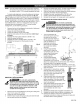
Owner's Manual ® AIR COMPRESSOR Oil Lubricated Belt Drive, Electric 80 Gallon Vertical TOPS TM -Thermal Overload Protection System NOTE: These units DO NOT require a magnetic starter. Model No. 921.16477 ====================== CAUTION: Before using this product, read this manual and follow all its Safety Rules and Operating Instructions. Sears Brands Management www.craftsman.com 4/7/2010 Part No.
1_:I:]|: WARRANTY [o]_ [a_o]_ / i :__ / l_'_ ....................................... SPECIFICATION CHART SAFETY GUIDELINES GLOSSARY OF TERMS ............................ ............................. 2 SERVICE INTERVAL ............................... 11 2 TROU BLESHOOTI NG CHART 12 3-4 ............................. ....................................... 5 ASSEMBLY ....................................... 5 COMPRESSOR ............................
Thefollowing information relates toprotecting YOURSAFETY andPREVENTING EQUIPMENT PROBLEMS. Tohelpyourecognize thisinformation, weusethefollowing symbols. Please readthemanual andpayattention tothesesections. __ - A POTENTIAL HAZARD THAT WILL CAUSE SERIOUS INJURY OR LOSS OF LIFE. _k___ A POTENTIAL HAZARD THAT COULD CAUSE SERIOUS INJURY OR LOSS OF LIFE. - A POTENTIAL HAZARD THAT MAY CAUSE MODERATE INJURY OR DAMAGE TO EQUIPMENT. RISK OF FIRE OR EXPLOSION. Never spray flammable liquids in a confined area.
RISK OF FIRE. Unattended operation of this compressor could result in personal injury or property damage. To reduce the risk of fire, do not allow the compressor to operate unattended. Always disconnect electrical power by turning the pressure switch to off and drain the tank daily or after each use. Air obtained directly from the compressor should never be used to supply air for human consumption. The air stream may contain carbon monoxide, toxic vapors, or solid particles from tank.
BASIC AIR COMPRESSOR COMPONENTS The basic components of the air compressor are the electric motor, pump, pressure switch and tank (see Fig. 1). The electric motor (see A) powers the pump. TOPS senses both temperature and current, providing more complete motor overload protection than a magnetic starter, which senses only current. If TOPS senses an overload condition, it wilt automatically shutdown the compressor.
__[[[_Risk ofbursting, resulting ininjury. Never useplastic pipeforcompressed air. _lhl__Never uselubricator forpaintspraying orsimilarapplications. A B C D E F G H J K L M N P R T Airflow Feeder line Drainleg Moisture trapwithdrain Non-lubricated supplyline 1/4turnvalve Bypass Airdryeroraftercooler Linefilter Dripteewithdrain Air/water filterwithpetcock Regulator Lubricator Quickcoupler Airhosetotool Flexible airline Air dryers and after coolers An air dryer or aftercooler moisture trap and drain.
Main Power Disconnect Install a main power disconnect switch in the power line to the compressor, near the compressor's location. It is operated manually, but when it is in the ON position, the compressor will start up or shut down automatically based on air demand. ALWAYS operate this switch to OFF when the compressor is not being used.
BREAK-IN NOTE: 1. 2. 3. before starting. If the compressor will not start, relocate it in a warmer location. OF THE PUMP The pump is shipped with breakiin oil which should be changed after the first 8 hours of operation. SHUTDOWN 1. 2. 3. Make sure the power is connected at the power panel. Check the oil level in the pump (see "Checking the Oil" in the maintenance section). Open the petcock (see C). Turn the pressure switch to the OFF position (see A). Shut OFF the main power disconnect switch.
guard removed. Serious injury could occur from contact with moving parts. MAINTENANCE __ To avoid personal injury, always shut off and unplug the compressor and relieve all air pressure from the system before performing any service on the air compressor. Proper belt tension and pulley alignment must be maintained for maximum drive efficiency and belt life. The correct tension exists if a deflection (see A) of 112" (13 mm) occurs by placing 10 lbs. (4.
NOTE:Oncethemotorpulleyhasbeenmoved fromitsfactory setlocation, thegrooves oftheflywheel andpulleymust bealigned towithin1/16"toprevent excessive beltwear. 4. Tocheckpulleyalignment, remove thebeltguardandplace astraightedge (seeA)against thepumpflywheel (seeB)(See 6. 7. 8. Fig. 9). Measure and record the distance from the straightedge to the edge of the drive belt at point C. Then measure the distance from the straightedge to the edge of the drive belt again at points D and E.
CLEANING THEAIR FILTER STORAGE A dirty air filter will reduce the compressor's performance and life. To avoid any internal contamination of the 8 C Before storing the compressor for a prolonged period, use an air blow gun to clean all dust and debris from the compressor. Disconnect the power cord and coil it up. Pull the tank safety valve to release all pressure from the tank. Drain all moisture from the tank. Clean the filter element and filter housing; replace the element if necessary.
Note: Troubleshooting problems may have similar causes and solutions. PROBLEM POSSIBLE CAUSE SOLUTION Excessive current draw trips circuit breaker or Low voltage/motor Check that power supply is adequate and that compressor dedicated circuit. motor reset switch Drive belt tension too tight Readjust belt tension. Restricted air passages Inspect and replace transfer tubes or the check valve, (see "To replace or clean check valve" in the maintenance section).
\\ Item Part No. Articulo N° de pieza Article No / P Qty Cant.
NOTES: //_{_ Torque to 40-65 Ibdn Torsi6n hasta 4,5-7,3 N.m Serrez de 40 ,&,65 Ibs-in Torsi6n hasta Torque to 45-655,1-7,3 Ibdn N.m Serrez de 45 _, 65 Ibs-in _: 7", /,,'-l{_ Torque to 130-180 Ibdn. Torsi6n hasta 14 7-20,3 N.m Serrez de 130 A 180 Ibsdn. Ji 27 .... 1! ....... 10 ,f _Y ............... f .........
Item Articulo Article 1 2 3 4 5 6 7 ,: 8 9 10 11 12 13 14 Part No. Num / P No/P 125-0204 103-0073 146-0016 008-0052 006-0153 N/A N/A 125-0203 N/A 114-0626 N/A N/A N/A 026-0299 Qty Cant Qte 1 4 1 1 1 4 12 1 1 1 1 4 8 1 15 15A 15B 15C 15D 16 17 021-0257 513-0001 512-0043 512-0041 072-0001 098-3870 145-0082 18 19 20 21 22 Description Beltguard (outer) Fastener Key Belt, BX64 Pulley Screw, 3/8-16 x 3/4 Washer, fiat 3/8" Beltguard (inner) Screw, 10-24 x .50" Bracket Bolt, 5/16" x .
1 "'_ 2 PUMP - 040-0387 Specifications ......2 _Z_" ...... o 18 ........ Weight 145 LBS Oil Capacity 21 OZ Lubrication Synthetic, nondetergent, air compressor oil 690 Max RPM ......... 2I NOTES: Torque /]\1'_ 24 /0", / _ ....... _7 to 10 Ibs-ft Serrez de 10 Ibs-ff Torsi6n hasta 13,6 N.m Torque to 25 Ibs-ft Serrez de 251bs-ft. Torsi6n hasta 34,0 Norn _,\ J_,, Torque to 281bs-ft Serrez de 28 Ibs-ff Torsi6n hasta 38.0 N.m A, /'_ Torque to 43 Ibs-ft Serrez de 43 Ibs-ff.
Item Part No. Num / P Qty Cant 12 No / P 019-0242 Qte 1 13 019-0243 14 15 019-0244 Articulo Article Description Spacer, h.p. discharge Descripcion Espaciador, descarga Description Entretoise, decharge 1 Spacer, I.p. inlet Espaciador, Entretoise, admission 1 Spacer, h.p. discharge 043-0209 043-0210 1 1 Intake valve assy, I.p. Exhaust valve assy, I.p. Espaciador, descarga Conjunto de valvula 17 18 046-0310 2 Copper gasket valve I.p. 043-0211 1 Intake valve assy, h.p.
GARANTiA ....................................... 18 INTERVALOS CUADRO DEESPECIFICACIONES ................... 18 CUADRO DE DETECCION DE FALLOS ................ PAUTAS DESEGURIDAD ........................ 19-20 GLOSARIO DET¢:RMINOS ......................... 20 RESUMEN GENERAL .............................. 21 MONTAJE ....................................... 21 INSTALACION TiPICA .............................. 22 CONTROLES DELCOMPRESOR .................... 23 DE SERVICIO .....................
La informaci6n ayuda A que sigue para reconocer I_il_"_J'_- se refiere a la protecci6n esta informaci6n, usamos de SU SEGURIDAD los siguientes y ta PREVENCION simbolos. DE PROBLEMAS Lea por favor el manual y preste DEL EQUIPO. atenci6n a estas Como secciones. RIESGO POTENCIAL DE LESIONES GRAVES O PI_RDIDA DE LA VIDA. ___ V_,_m_v_=I:_II=I_[_]P'_,I- RIESGO POTENCIAL DE LESIONES GRAVES O PI_RDIDA DE LA VIDA.
RIESGO DE EXPLOSION. oNunca intente, valvula por ningQn motivo, ajustar la valvula de seguridad la valvula ha sido preconfigurada de seguridad, mangueras RIESGO _ _ DE Dejar el compresor INCENDIO RIESGO PARA RESPIRACION. LA existe el riesgo de que se produzcan de plastico lineas de distribuci6n de seguridad o pvc para aire comprimido.
COMPONENTES BASICOS DEL COMPRESOR encendido", el interruptor reinicia el motor automaticamente bomba vuelve a comprimir el aire. DE AIRE Los componentes basicos del compresor de aire son el motor electrico, la bomba, el interruptor de presi6n y el dep6sito (Fig. 1). y la El motor electrico (ver A) acciona la bomba.
F \ H / L M A_ ,ml_ r-'l.A'lailia_L_r-'NExiste el riesgo de lesiones pour quemaduras. Nunca use tuberia de plastico para aire comprimido. __Nunca use lubricador para rociar pintura o aplicaciones similares.
Interruptor principal de alimentaci6n Instale un interruptor principal de desconexi6n en ta linea de alimentaci6n hacia et compresor, cerca de la ubicaci6n de este. Este interruptor apaga et compresor.
PROBLEMAS CAUSADOS circuito. Si el cableado no es adecuado, el voltaje caera unos 20 a 40 voltios al arrancar. Un voltaje bajo o un circuito sobrecargado puede dar como resultado un arranque lento que hara que salte el disyuntor, especialmente en epocas frias. POR BAJO VOLTAJE Un voltaje bajo causara dificultades en el arranque o una sobrecarga.
ARRANQUE ENI_POCAS DEBAJATEMPERATURA Enepocas defrio,asegQrese dequelosfittrosdeaireestan 3. limpios. NOTA: Useaceite sintetico no-detergente paraetcompresores deaire. Abralavalvula dedrenaje (veaC)paradisminuir lapresi6n detcompresor hastacerobarantesdearrancar. Sietcompresor noarranca, muevalo hastaunlugarmascaliente. 2, PARADA 1. 4, Coloque el interruptor de presi6n en la posici6n de apagado OFF (vea A). Desactive et interruptor principal de alimentaci6n.
5. Verifique paraasegurarse dequelatensi6n siguesiendo la correcta. 6. Vuelvaa instalar elprotector delacorrea. Todas tas piezasm6vites debenestarprotegidas. 2, 3. 4. Fig. 8 Po_eo 5, 6, 7. 8, de vuelta los 4 clips del protector de la correa con una llave de 5/8 pulg. Afloje los pernos de montaje del motor. Afloje el tornillo de fijaci6n de ta potea del motor. Alinee la polea del motor con el volante de la bomba (C-D-E deben ser iguales).
compresi6n. Vuelva a colocar la manguera de transferencia y apriete las tuercas de compresi6n. 10. Realice el procedimiento "Marcha inicial de la bomba" en la secci6n Instrucciones operativas para asegurarse de que no haya fugas y de que la valvula de retenci6n este funcionando correctamente. PARA CAMBIAR O LIMPIAR LA VALVULA DE RETENCION 9. __Esta unidad arranca automaticamente.
Nota: Los problemas de deteccion de fallos pueden tener causas y soluciones PROBLEMA CAUSA POSIBLE Consumo excesivo de la corriente hace saltar el cortacircuito o el interruptor de restablecimiento del motor Voltaje bajo/sobrecarga SOLUCION del motor Verifique que el suministro de energia sea el adecuado y que el compresor se encuentre conectado en un circuito dedicado. Si esta usando un cable prolongador, intente utitizar el equipo sin el mismo.
/If;1-'] II1:11|] :F,,,_I_v_ V_,_I II I":1_,!:[,,,,_ GARANTIE ................................... TABLEAU DES SPg:CIFICATIONS CONSIGNES DE S¢:CURIT¢: GLOSSAIRE DES TERMES VUE D'ENSEMBLE ................ 29 ENTRETIEN 29 ENTRETIEN P#RIODIQUE .................. 30-31 ...................... 31 ............................. ................................ 32 INSTALLATION TYPIQUE 33 ....................... DU COMPRESSEUR SPg:CIFICATIONS €:LECTRIQUES ............... ......................
Les informations suivantes aider & identifier sections. la nature __ concernent VOTRE S#CURIT# de ces informations, - DANGER V-_\I_ _ i_ | _,,'_I_'i _ _V_l__ | m POTENTIEL - DAN et LA PROTECTION nous utilisons POUVANT GER les symboles ENTRAiNER POUVANT CAUSER DU MAT#RIEL suivants. Veuillez DE GRAVES DES BLESSU CONTRE BLESSURES RES LES PANNES. lire le manuel OU GRAVES et pr6ter Pour vous attention & ces LA MORT. VOIRE MORTELLES.
A V__\vj :1_ / _ :hV_ 1:1_I I1 RISQUE D'I_CLATEMENT. •Ne pas ajuster la soupape toutes les garanties. blessures corporelles _ "_ = RISQUE D'INCENDIE en plastique en acier galvanise sous aucun pretexte.
#L#MENTS DE BASE DU COMPRESSEUR met en marche le moteur automatic uement et la pompe recommence &compresser Fair. D'AIR Les etements de base du compresseur d'air sont le moteur electrique, la pompe, le manostat et le reservoir.
F \ H / L M I"1Jivi =1t']l i ["!"1 =l_VA I=1#/ Ii Risq ue d'eclatement pouvant entrafner des blessures. N'utilisez jamais de tuyau en plastique pour de l'air comprime, __N'utitisez Pas de lubrificateur pour les travaux de pulverisation des applications similaires.
Sectionneur de tension lnstallez principale un sectionneur d'alimentation du compresseur, compresseur. Ce sectionneur a proximite est actionne Iorsqu'il est SOUS TENSION, s'arr6te automatiquement ce sectionneur Interrupteur de pression manuellement, le compresseur sa pression mais reservoir se met en marche ou Iorsque le compresseur la pression (voir A) sur la position OFF quand vous n'utilisez de le debrancher.
Si le c_blage n'est pas ad¢quat, la tension baisse de 20 a 40 volts au moment de la mise en marche. La mise en marche lente du INSTRUCTIONS compresseur m¢tallique causant d'une insuffisance sp¢cialement le d¢clenchement du disjoncteur de tension ou de la surcharge peut r¢sulter du circuit, REMARQUE conducteur V¢rifiez que le panneau 2. V¢rifier le niveau d'huile de la pompe la section de tension est sous tension.
ENTRETIEN AJUSTEMENT _L'\VJ=l;'lll["!'l=l_VAl=l_ll/;Icet appareil se met automatiquement. TOUJOURS arr_ter le pouvoir disjoncteur principal, et purger toute la pression du systeme avant I 'entretien du compresseur, et Iorsque le compresseur n'est pas utilise. Ne pas utiliser I'appareil sans les protections ou carter de courroie, des blessures graves en cas de contact avec les pieces mobiles. L'entretien regulier de l'appareil permettra d'assurer un fonctionnement sans problemes.
ALIGNEMENT REMPLACEMENT DE LA COURROIE D'ENTRAINEMENT DE LA POULIE REMARQUE : La tension de ta courroie et t'alignement de la poulie se font simultanement. Chaque procedure est decrite separ6ment par souci de clart& A V-'\VA=lt'_i_'%'t=hVAl=l_llACetappareil se met automatiquement. TOUJOURS arreter le pouvoir disjoncteur principal, et purger toute la pression du systeme avant I 'entretien du compresseur, et Iorsque le compresseur n'est pas utilise.
5. Enutitisant uncrayon ouuntournevis, est directement expose & des saletes et de la peinture. pousser deticatement tedisque duclapet de o,c_yo_VITRIFICATION DE LA SOUPAPE DE DISCHARGE hautenbas.Siledisque duclapet nese deplace paslibrement dehautenbas, Tirer sur la bague de ta soupape de s0rete du reservoir verifier siteclapet denon-retour doitetre quotidiennement afin d'assurer que ta soupape fonctionne nettoye ouremplac& correctement et pour nettoyer la soupape de toute obstruction 6.
Remarque : Les problemes de depannage peuvent avoir des causes et des solutions similaires.
Your Home For troubleshooting, product manuals and expe_ advice: www.managemylife.com For repair - in your home - of all m_or brand appliances, lawn and garden equipment, or heating and cooling systems, no matter who made it, no ma_er who sold it! For the replacement pa_s, accessories and owner's manuals that you need to do-it-yourself. For Sears professional installation of home appliances and items like garage door openers and water heaters.