S_EA/ S OWNER'S MANUAL MODEL NO. 987.799601 ® 5 Horsepower Caution: Read and Follow All Safety Rules and Instructions Before Operating This Equipment. CHIPPER/VAC with Wheel Adjusters • • • • • Assembly Operation Customer Responsibilities Service and Adjustment Repair Parts Sears, Roebuck and Co., Hoffman Estates, IL 60179 FORM 1902963 (11/94) U.S.A.
SAFETY RULES ,_ NOT CONTACT SPARK PLUG TO PREVENT ACCIDENTAL STARTING WHEN SETTING UP, CAUTION: ALWAYS DISCONNECT WIRE AND PLACE WIRE WHERE IT CANTRANSPORTING, ADJUSTING, OR SPARK MAKING PLUG REPAIRS. _tk IMPORTANT YOUR UNIT IS EQUIPPED WITH A SAFETY INTERLOCK SYSTEM TO MINIMIZE INJURY. DO NOT ATTEMPT TO DEFEAT THIS SYSTEM UNDER ANY CIRCUMSTANCES. TRAINING: • Read this Owner's Manual carefully before operating this equipment. Be thoroughly familiar with the controls and the proper use of this equipment.
OPERATION: Do not operate the chipper if the chipper chute flap is damaged or missing • Before starting this equipment, make certain that the chipper chute, vacuum inlet, discharge opening, and blower deflector are empty. Disconnect spark plug wire before making these check& Keep your face and body safely away from the chipper chute When chipping, stand on either side of chute and keep arms perpendicular (at a 900 angle) to chute inlet. * Never carry passengers on this equipment.
MAINTENANCE AND STORAGE: • When equipment is stopped for servicing, inspection, storage, or to change an attachment or accessory, make sure the spark ptug wire is disconnected from the spark plug Allow the engine to cool before making any inspections, adjustments, etc • Store this equipment where children will not have access.
CONGRATULATIONS onyourpurchase of a Sears Craftsman ChipperNac.it hasbeendesigned, engineered and manufactured to give you the best possible dependability and performance. Should you experience any problems you cannot easily remedy, please contact your nearest Sears Service Center or Retail Store. We have competent, well-trained technicians and the proper tools to service or repair this machine.
TABLE OF CONTENTS SAFETY RULES ................................................... PRODUCT SPECIFICATIONS WARRANTY .......................................................... CHIPPER/VAC ASSEMBLY .............................. ATTACHMENTS .......................... ........................................................... 2 SERVICE AND ADJUSTMENTS 5 STORAGE 5 TROUBLESHOOTING 7 DECALS ..............................................................
ATTACHMENTS This attachment was available when the chipper/vac was purchased° It is available at most Sears retail outlets and service centers. Most Sears stores can also order repair parts for you, when you provide the model number of your chipper/vac. VACUUM HOSE The optional vacuum hose attachment allows you to extend the reach of the machine by 10 feet to easily reach in, around, under and behind bushes, shrubs, trees, fences, lawn furniture, etc.
ASSEMBLY Read these instructions in their entirety before you attempt to assemble your new chipper/vaco Your new chipper/vac has been completely assembled at the factory, except for the items shown in Figure 1.. To ensure proper operation of your chipper/vac, all nuts and bolts must be securely tightened when changing the configuration of the machine Use the correct tools as necessary to ensure proper tightness.
ASSEMBLY ASSEMBLY CONFIGURATIONS Your machine has been partially assembled at the factory. The remaining assembly steps should be done on a clean, level surface, Choose the mode of operation from the pictures below and then go to the page for assembly of the chipper/vac in the desired configuration..
ASSEMBLY ASSEMBLY FOR WALK-BEHIND VACUUMING OR USING THE CHIPPER 4. Pull the screen (A) out of the discharge opening.. Reinstall the rods and hair pin clips on the screen for safekeeping. IMPORTANT: THE HAIR PIN CLIPS SUPPLIED WITH THE SCREEN ARE THE ONLY STYLE FASTENERS THAT SHOULD BE USED° DO NOT USE SUBSTITUTES OR FAILURE OF EQUIPMENT OR PERSONAL INJURY COULD RESULT. 5.
ASSEMBLY STEP 3: ADJUST THE VACUUM INLET HEIGHT CAUTION STEP 2: INSTALL COLLECTION The vacuum inlet height can be adjusted to six different settings in approximately 1/2" increments.
ASSEMBLY 1,1,,, ASSEMBLY FOR BLOWER ,,,,,,,,,,,,,,,, = L = J =LJJui,,,Jiu,i,u,,, ,,,,,,,,i, OPERATION STEP 2: ADJUST HANDLEBARS If the handlebars are in the vacuum position, they must be adjusted to the "blower" position for blower operation. 1. Squeeze the handlebar end (see decal "Push in Here") toward the center of the machine and swing the handlebars over to the front of the machine, 2. Release the handlebars ends in the "blower" notches (A), See Figure 7.
ASSEMBLY STEP 4: REMOVE THE SHREDDER SCREEN For maximum air flow, remove the shredder screen before insta!iing the blower deflector 1. The screen (A) is held in place by two long rods (B and C) and hair pin clips (D), See Figure 8, 2. To remove the rear rod (B), remove the hair pin clip (D) and pull the rod out through the bottom of the deck° 3. Use sturdy supports to prop up the right side of the machine a few inches,.
ASSEMBLY ASSEMBLY FOR OPTIONAL HOSE OPERATION VACUUM Handlebars in Vacuum Position NOTE: The optional Vacuum Hose is designed for stationary vacuuming operation only, STEP 1: MOVE HANDLEBARS POSITION TO VACUUMING 1. Stop the engine, disconnect the spark plug wire from the spark plug, and make sure that all moving parts have come to a complete stop, Figure 11: Handlebar position for vacuuming. 2.
ASSEMBLY STEP 3: REMOVE THE SHREDDER SCREEN For maximum air flow, remove the shredder screen before installing the vacuum hose., t. The screen (A) is held in place by two long rods (B and C) and hair pin clips (D) (see Figure 13). 2. To remove the rear rod (B), remove the collection bag (if installed). Then, remove the hair pin clip and pull the rod out through the bottom of the deck, A 3.
ASSEMBLY H, ,,i,llllllliH i i STEP 5: INSTALL BAFFLE PLATE The baffle plate, which is included only with the optional vacuum hose, concentrates the suctioning power of the machine into the hose by blocking the air flow underneath the front of the machine. To instali the baffle plate, position the plate underneath the front of the deck and snap it into place as shown in Figure 15.
OPERATION KNOW YOUR CHIPPERiVAC READ THIS OWNER'S MANUAL AND SAFETY RULES BEFORE OPERATING YOUR CHIPPERNACo Figure 17 identifies the following key features and controls on your machine: (G) RECOIL STARTER ROPE: Used to start the engine_ (H) BLOWER DEFLECTOR: Directs air flow when machine is used in blower configuration. (I) SAFETY INTERLOCK ROD: Part of the safety interlock system which stops the engine if either the collection bag or blower deflector is not installed.
OPERATION BEFORE STARTING ENGINE STEP t: ADD OIL TO ENGINE DAHaER 1, The machine was shipped without oil in the engine The engine requires approximately 2t ounces of oil RotatingCuttingBladesWill Cause Serious Personal Injury! 2, Only use high quality detergent oil rated with the APJ.
OPERATION To Add Gasoline 1, Stop the engine and wait for all moving parts to come to a complete stop. Disconnect the spark plug wire and secure it away from the spark plug, Allow the engine and muffler to cool for at least three minutes, 2. Clean area around fuel fill cap and remove cap (A in Figure 19) from fuel tank_ 3. Use a clean funnel to fill the fuel tank to 1/2 inch below the bottom of the filler neck (to provide room for fuel expansion). 4.
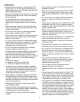
OPERATION GENERAL OPERATION Understanding how your machine works will help you achieve the best results when using the Chipper/Vac+ Read the following explanation before using the machine and see Figure 21 which shows the internal workings of the ChipperiVac_ A (A) Chipper Chute (B) Chipper Cutting Blade F (C) Shredder Screen (D) Processing Chamber (E) Fan Blade (1 of 4) (F) Discharge Opening Figure 21: Cutaway view.
OPERATION VACUUMING CHIPPING OPERATION Chipping operation also takes place in the processing chamber° Branches fed down through the chipper chute enter the processing chamber where a hardened steel chipper blade, mounted on the spinning flywheel, slices the material into small chips. The chips are then propelled out from the processing chamber through the discharge opening into the collection bag.
OPERATION WALK-BEHIND VACUUMING OPERATION DANGER To Prevent Personal Injury or Property Damage: • Cutting blades begin to rotate when the engine starts and slow down gradually after the engine is shut off. Do not allow handsor any other part of the body or clothing inside the vacuum hose opening, blower discharge opening, chipper chute, or near any mowng parL • Before inspecting, cleaning, or servicing the machine, stop the engine and make sure that all moving parts have come to a complete stop.
OPERATION VACUUM HOSE OPERATION DANGER To Prevent Personal Injuryor Property Damage: * Cutting blades begin to rotate when the engine starts and slow down gradually after the engine is shut off. Do not allow hands or any olher part of the body, or clothing inside the vacuum hose opening, blower dischargeopening, chipper chute, or near any moving part. - Before inspecting, cleaning, or servicing the machine, stop the engine and make sure that all moving parts have come to a complete stop.
OPERATION BLOWER OPERATION DANGER To PreventPersonal Injury or Properly Damage: ,, Cutting blades begin to rotate when the engine starts and slow down gradually after the engine is shut off. Do not allow hands or any other part of the body or clothing inside the vacuum hose opening, blower dischargeopening, chipper chute, or near any moving part. • Before inspecting, cleaning, or servicing the machine, stop the engine and make sure that all moving parts have come to a complete stop.
OPERATION CHIPPER OPERATION DANGER To PreventPersonal Injury or Property Damage: • Cutting blades begin to rotate when the engine starts and slow down gradually after the engine is shut off. Do not allow hands or any other part of the body or clothing inside the vacuum inlet, chipper chute, dischargedeflector or near any moving part. ,, Before inspecting, cleaning, or servicing the machine, stop the engine and make sure that all moving parts have come to a complete stop.
OPERATION CLEARING JAMS AND CLOGS For all vacuuming operations: 1. Check that the collection bag is not overfilled 2. While the bag is removed, check that the discharge opening is not clogged° WARNING For walk-behind Before inspecting,cleaning or servicingthe machine, stop the engine and make sure that all moving parts have come to a completestep° Disconnectthe spark plug wire and secure it away from the spark plug, Failure to follow this instruction could result in personal injury, vacuuming: 1.
CUSTOMER IMPORTANT SERVICE RESPONSIBiLITiES MESSAGE CAUTION i Perform the Maintenance Schedule listed in the chart below to ensure the proper performance and long life of your machine.
CUSTOMER RESPONSIBILITIES To Change the Oil 1, Change the oil while engine is still warm from recent operation. Stop engine and make sure that all moving parts have come to a complete stop. Disconnect spark plug wire and secure it away from spark plug. 2. The oil drain plug (B in Figure 27 on Page 27) is located at the bottom of the dipstick tube,. 3.
CUSTOMER RESPONSIBILITIES Check The Spark Plug 1, Stop the engine and make sure that all moving parts have come to a complete stop. Disconnect the spark plug wire and secure it away from the spark plug. Electrodes 2, Clean the area around the spark plug to prevent debris from falling into the spark plug hole_ .030 Gap ...,,, \ 3, Remove and inspect the spark plug. Check the electrode gap with a wire feeler gauge and set the gap at _030", if necessary.
SERVICE AND ADJUSTMENTS REPLACE THE CHIPPER CUTTING d. Re-install the fuel line on the fuel tank fitting and secure it in place with the hose clamp. Install gas cap on fuel tank. BLADE Over time, the chipper cutting blade edge (A in Figure 33 on Page 31) will dul!. Sharpen or replace the blade when the chipper no longer cuts efficiently, FuelTank _3 Discard a cracked or severely nicked blade because the blade could break apart and cause personal injury.
SERVICE AND ADJUSTMENTS 14. Install the short safety interlock wire terminal and the lockwasher on one of the mounting bolts and install it at the rear of the machine above the left side of the blower opening. Connect the long interlock wire to the terminal above the muffler. Replace the other two mounting bolts and tighten all three bolts to 60-65 Ibs-in.
STORAGE OFF-SEASON d. Change the oil if it has not been changed in the last three months, See Page 28 STORAGE e. Lubricate the piston/cylinder area,, First, remove the spark plug, Then, squirt approximately '1/2 ounce of clean engine oil into the spark plug hole_ Cover the spark plug hole with a rag to absorb oil spray and then rotate the engine by pulling the starter rope two or three times. Finalty, re-install the spark plug.
TROUBLESHOOTING POINTS Before performing any of the corrections in this Troubleshooting Chart, refer to the appropriate information contained in this Manual for the correct safety precautions and operating or maintenance procedures.
TROUBLESHOOTING PROBLEM Lossof Vacuum UnusualVibrationor Noise POINTS POSSIBLECAUSE CORRECTION 1 Vacuuminletor vacuumhosec_ogged, 1 Checkfor and removeanyobstruction (Page26) 2 Collectionbagfull 2 Removeand emptybag(Page12) 3 Dischargeopeningclogged 3 Removecollectionbagto clean opening(Page12) 4 Processingchamberclogged 4 Checkfor andremoveany obstruction (Page26), 5. Enginenotreachingfull RPM 5 See"EngineRunsPoorly"at beginning of chart, 1.
DECALS ROTATING CUTTINGBLADESANDTHROWN OBJECTS Wit,L CAUSESERIOUSINJURY! • KEEPCLEAROF DISCHARGEOPENINGAT ALLTIMES, = DO NOTOPERATEWITHOUTCOLLECTIONBAG OR BLOWERDEFLECTORINSTALLED_ ROTATINGCUTTINGBLADESWILL CAUSESERIOUSINJURYf INLETCAPORHOSE MUSTBEINSTALLED° • DONOT OPERATEtF SAFETYINTERLOCKIS BROKEN OR BECOMESDEFECTIVE.SEE OWNER/OPERATOR _.MANUAL __ ,,, i DISCHARGEOPENINGTOAVOIDSERIOUSINJURY. HOT SURFACES CAN CAUSE SEVERE BURNS DO NOTTOUCH MUFFLEROR ADJACENTAREAS.
CRAFTSMAI!5 HP CHIPPER/VACMODELNUMBER987.
CRAFTSMAN5 HP CHIPPER/VACMODELNUMBER987.799601 REF No_ PART No. 1 2 DESCRIPTION REF No. QTY. 143,955002" Engine,5 HP 1762042 Thread-FormingScrew 318-16x 1" 3 1763390 FlangeScrew,5/16q3 x 1" ............ 13 1763255 Fanand ChipperDiscAssy ............... 1 1104338 Key,114x 1/4 x 2" ...................... 1 1100010 Capscrew,318-24x 1-1/4" .......... 1 ConicalWasher 1 1756993 Washer ............................... 4 1185831 1763261 Inlet Housing....................... I l 1763262001 Divider Plate........
CRAFTSMAN4-CYCLE ENGINE : MODELNO. 143,955002 7-301 11287 MODELand SERIALIZe. 370 NUMBERSHERE 260 .262 " 292 400 29O I_'_ 292 135 130 -7 126 276",-._. , 120 119 277,A.,_ _=.
CRAFTSMAN4-CYCLE ENGINE Ref.
CRAFTSMAN5 HP CHiPPER]VACMODELNUMBER987.799601 REWINDSTARTERNO. 590732 (Fig. 2) CARBURETORNO. 632670 (Fig. 1) [_ef. t 2 4 5 6 7 16 25 27 28 29 30 31 35 35A 40 44 48 Part No, 631615 631767 631184 631183 632504 650506 631775 631867 631024 632O19 631028,_ 631021 , 631022 632694 632647 632503 27110 631027 Ref. No. Part Name Throttle Shaft & Lever Assembly Throttle Return Spring Dust Seal Washer Dust Seal (Throttle) Throttle Shutter Shutter Screw Fuel Fitting Float Bowl Float Shaft Float .
NOTES 41
NOTES 42
NOTES 43
CRRFrSMRN ® OWNER'S UAL MODEL NO. 987.799601 5 Horsepower CHIPPER/VAC with Wheel Adjusters Each Chipper/Vac has its own model engine has its own model number. The model number for your machine left side of the unit. number_ Each will be found on the The model number for the engine will be found engine's blower housing above the spark plug. on the All parts listed herein may be ordered through Sears, Roebuck and Co. Service Centers and most Retail Stores.