OPERATOR’S MANUAL MANUAL DEL OPERADOR 7-1/4 in., 19.2 Volt Compound Miter Saw Sierra ingleteadora combinada de 7-1/4 pulg., de 19.2 V MODEL NO. / NÚMERO DE MODELO 315.BT2010 WARNING: To reduce the risk of injury, the user must read and understand the operator’s manual before using this product. 45 ADVERTENCIA: Para reducir el riesgo de lesiones, el usuario debe leer y comprender el manual del operador antes de usar este producto.
TABLE OF CONTENTS / ÍNDICE DE CONTENIDO ENGLISH ESPAÑOL Warranty.......................................................................2 Introduction..................................................................2 General Safety Rules............................................... 3-4 Specific Safety Rules...................................................5 Symbols.......................................................................6 Glossary of Terms....................
GENERAL SAFETY RULES WARNING: Read and understand all instructions. Failure to follow all instructions listed below, may result in electric shock, fire and/or serious personal injury. READ ALL INSTRUCTIONS USE RECOMMENDED ACCESSORIES. Consult the operator’s manual for recommended accessories. The use of improper accessories may result in injury. NEVER STAND ON TOOL. Serious injury could occur if the tool is tipped or if the cutting tool is unintentionally contacted.
GENERAL SAFETY RULES NEVER START A TOOL WHEN ANY ROTATING COMPONENT IS IN CONTACT WITH THE WORKPIECE. DO NOT OPERATE A TOOL WHILE UNDER THE INFLUENCE OF DRUGS, ALCOHOL, OR ANY MEDICATION. WHEN SERVICING use only identical replacement parts. Use of any other parts may create a hazard or cause product damage. DOUBLE CHECK ALL SETUPS. Make sure blade is tight and not making contact with saw or workpiece before connecting to power supply.
SPECIFIC SAFETY RULES NEVER hand hold a workpiece that is too small to be clamped. Keep hands clear of the cutting area. NEVER reach behind, under, or within three inches of the blade and its cutting path with your hands and fingers for any reason. NEVER reach to pick up a workpiece, a piece of scrap, or anything else that is in or near the cutting path of the blade. AVOID AWKWARD OPERATIONS AND HAND POSITIONS where a sudden slip could cause your hand to move into the blade.
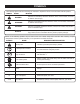
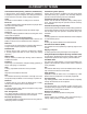
SYMBOLS The following signal words and meanings are intended to explain the levels of risk associated with this product. SYMBOL SIGNAL MEANING DANGER: Indicates an imminently hazardous situation, which, if not avoided, will result in death or serious injury. WARNING: Indicates a potentially hazardous situation, which, if not avoided, could result in death or serious injury. CAUTION: Indicates a potentially hazardous situation, which, if not avoided, may result in minor or moderate injury.
GLOSSARY OF TERMS Anti-Kickback Pawls (flooring, radial arm, and table saws) A device which, when properly installed and maintained, is designed to stop the workpiece from being kicked back toward the front of the saw during a ripping operation. Arbor The shaft on which a blade or cutting tool is mounted. Bevel Cut A cutting operation made with the blade at any angle other than 90° to the table surface. Compound Cut A cross cut made with both a miter and a bevel angle.
FEATURES PRODUCT SPECIFICATIONS Arbor.......................................................................... 5/8 in. Blade Diameter.......................................................7-1/4 in. No Load Speed..................................... 4,500 r/min. (RPM) Motor................................................................ 19.2 Volt DC Cutting Capacity with Miter at 0°/Bevel 0°: Maximum lumber sizes...................... 1-1/2 in. x 4-1/4 in.
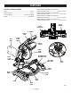
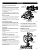
FEATURES KNOW YOUR COMPOUND MITER SAW See Figure 1. The safe use of this product requires an understanding of the information on the tool and in this operator’s manual as well as a knowledge of the project you are attempting. Before use of this product, familiarize yourself with all operating features and safety rules. LOCK PIN MITER LOCK LEVER 7-1/4 in. BLADE REAR BRACKET/ CARRYING HANDLE A 7-1/4 in. blade is included with the compound miter saw. It will cut materials up to 1-1/2 in. thick or 4-1/4 in.
FEATURES SWITCH TRIGGER See Figure 4. The saw will not start until you depress the switch lock with your thumb then squeeze the switch trigger. To prevent unauthorized use of the compound miter saw, remove the battery pack, and lock the switch in the off position. To lock the switch, install a padlock (not included) through the hole in the switch trigger. A lock with a long shackle of 5/16 in. diameter may be used. When the lock is installed and locked, the switch is inoperable.
LOOSE PARTS LIST The following items are included with your compound miter saw: Dust Bag Rear Bracket/Carrying Handle Work Clamp Operator’s Manual (not shown) Blade Wrench WORK CLAMP DUST BAG BLADE WRENCH REAR BRACKET/ CARRYING HANDLE Fig. 6 WARNING: The use of attachments or accessories not listed might be hazardous and could cause serious personal injury.
ASSEMBLY UNPACKING INSTALLING THE REAR BRACKET/CARRYING HANDLE This product requires assembly. Carefully lift miter saw base from the carton by the “D” handle and the saw base, and place it on a level work surface. See Figure 7. WARNING: A rear bracket is included with this miter saw to prevent tipping if the saw arm is released suddenly. Do not use this saw before installing the rear bracket and securely mounting the saw to a work surface or stand.
ASSEMBLY DUST BAG WARNING: Always make sure the compound miter See Figure 9. A dust bag is provided for use on this miter saw. It fits over the exhaust port on the upper blade guard. To install, squeeze the two metal clips to open the mouth of the bag and slide it on the exhaust port. Release the clips. The metal ring in the bag should lock in between the grooves on the exhaust port. To remove the dust bag for emptying, simply reverse the above procedure.
ASSEMBLY WORK CLAMP See Figure 10. The work clamp provides greater control by clamping the workpiece to the fence. It also prevents the workpiece from creeping toward the saw blade. This is very helpful when cutting compound miters. Depending on the cutting operation and the size of the workpiece, it may be necessary to use a C-clamp instead of the work clamp to secure the workpiece prior to making the cut.
ASSEMBLY TO INSTALL/REPLACE THE BLADE See Figures 11 - 12. WARNING: A 7-1/4 in. blade is the maximum blade BLADE BOLT COVER capacity of the saw. Never use a blade that is too thick to allow outer blade washer to engage with the flats on the spindle. Larger blades will come in contact with the blade guards, while thicker blades will prevent the blade bolt from securing the blade on the spindle. Either of these situations could result in a serious accident and can cause serious personal injury.
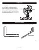
ASSEMBLY SOCKET HEAD SCREW(S) SOCKET HEAD SCREW(S) MITER LOCK LEVER MITER FENCE BLADE MITER TABLE 45 45 31.6 30 22.5 15 0 15 22.5 30 31.6 MITER FENCE Fig. 13 NOTE: Many of the illustrations in this manual show only portions of the compound miter saw. This is intentional so that we can clearly show points being made in the illustrations. Never operate the saw without all guards securely in place and in good operating condition. FRAMING SQUARE VIEW OF BLADE SQUARE WITH FENCE Fig.
ASSEMBLY SQUARING THE BLADE TO THE MITER TABLE See Figures 17 - 20. Remove the battery pack from the tool. Pull the saw arm all the way down and engage the lock pin to hold the saw arm in transport position. Lift the miter lock lever. Rotate the miter table until the pointer aligns with zero on the miter scale. Push the miter lock lever down to lock the miter table. Loosen bevel lock knob and set saw arm at 0° bevel (blade set 90° to miter table). Tighten bevel lock knob.
OPERATION WARNING: Do not allow familiarity with tools to TO INSTALL BATTERY PACK make you careless. Remember that a careless fraction of a second is sufficient to inflict serious injury. See Figure 21. Place battery pack in the saw. Align raised rib on battery pack with groove inside saw. WARNING: Always wear eye protection with side Make sure the latches on each side of the battery pack snap in place and that the battery pack is secured in the tool before beginning operation.
OPERATION CROSS CUT CUTTING WITH YOUR COMPOUND MITER SAW WARNING: When using a work clamp or C-clamp to secure your workpiece, clamp workpiece on one side of the blade only. The workpiece must remain free on one side of the blade to prevent the blade from binding in workpiece. The workpiece binding the blade will cause motor stalling and kickback. This situation could cause an accident resulting in possible serious personal injury.
OPERATION Grasp the saw handle firmly. Depress the switch lock with thumb then squeeze the switch trigger. Allow several seconds for the blade to reach maximum speed. INDICATOR POINT Slowly lower the blade into and through the workpiece. Release the switch trigger and allow the blade to stop rotating before raising the blade out of the workpiece. Wait until the blade stops before removing the workpiece from the miter table. BEVEL SCALE TO BEVEL CUT See Figures 24 - 25.
OPERATION Slowly lower the blade into and through the workpiece. COMPOUND MITER CUT Release the switch trigger and allow the saw blade to stop rotating before raising the blade out of the workpiece. Wait until the blade stops before removing the workpiece from the miter table. TO COMPOUND MITER CUT See Figures 26 - 27. A compound miter cut is a cut made using a miter angle and a bevel angle at the same time.
OPERATION Place the workpiece flat on the miter table with one edge securely against the fence. If the board is warped, place the convex side against the fence. If the concave edge of a board is placed against the fence, the board could collapse on the blade at the end of the cut, jamming the blade. When cutting long pieces of lumber or molding, support the opposite end of the stock with a roller stand or with a work surface level with the saw table. See Figure 28.
OPERATION CUTTING COMPOUND MITERS To aid in making the correct settings, the compound angle setting chart below has been provided. Since compound cuts are the most difficult to accurately obtain, trial cuts should be made in scrap material, and much thought and planning made, prior to making the required cut. PITCH OF SIDE 0° 5° 10° 15° 20° 25° 30° 35° 40° 45° 50° NUMBER OF SIDES 4 5 6 7 8 M- 45.00° B- 0.00° M- 44.89° B- 3.53° M- 44.56° B- 7.05° M- 44.01° B- 10.55° M- 36.00° B- 0.00° M- 30.00° B- 0.
OPERATION CUTTING CROWN MOLDING This compound miter saw does an excellent job of cutting crown molding. In general, compound miter saws do a better job of cutting crown molding than any other tool made. In order to fit properly, crown molding must be compound mitered with extreme accuracy. The two contact surfaces on a piece of crown molding that fit flat against the ceiling and the wall of a room are at angles that, when added together, equal exactly 90°.
OPERATION Type of Cut 33.85° Left side, inside corner 1. Top edge of molding against fence 2. Miter table set right 31.62° 3. Save left end of cut 33.85° Right side, inside corner 1. Bottom edge of molding against fence 2. Miter table set left 31.62° 3. Save left end of cut 33.85° 33.85° 45 45 Bevel Angle Setting 31.6 30 22.5 15 15 0 Left side, outside corner 1. Bottom edge of molding against fence 2. Miter table set left 31.62° 3. Save right end of cut 22.5 30 31.6 RIGHT Fig.
ADJUSTMENTS POSITIVE STOP ADJUSTMENTS WARNING: To prevent accidental starting that could cause serious personal injury, always remove the battery pack from the tool when assembling parts. The compound miter saw has been adjusted at the factory for making very accurate cuts. However, some of the components might have been jarred out of alignment during shipping. Also, over a period of time, readjustment will probably become necessary due to wear.
ADJUSTMENTS TO ADJUST THE MITER LOCK LEVER See Figure 33. Prior to squaring the saw blade to the fence, check and adjust the miter lock lever, if needed. In the “locked” position, the action of fully locking the miter lock lever should feel tight and secure. Considerable effort should be required to move the miter table. If the table moves easily when in the “locked” position, an adjustment of the miter lock lever is required. To adjust: Unplug the saw. Lock the miter lock lever completely.
MAINTENANCE LUBRICATION WARNING: When servicing, use only identical replacement parts. Use of any other parts can create a hazard or cause product damage. WARNING: Always wear eye protection with side shields marked to comply with ANSI Z87.1 during product operation. If operation is dusty, also wear a dust mask. All of the bearings in this tool are lubricated with a sufficient amount of high grade lubricant for the life of the unit under normal operating conditions.
NOTES 29 — English
FIGURE A 16 12 13 18 14 15 25 21 22 23 26 20 27 32 19 24 17 1 1 31 11 10 4 30 3 4 33 2 8 7 4 30 9 6 34 29 28 7-1/4 in. COMPOUND MITER SAW – MODEL NUMBER 315.
5 6 089100401902 089240001093 Blade (7-1/4 in. x 24t).................................... 1 Screw (M4 x 16 mm)...................................... 5 Screw (M5 x 30 mm, Pan Hd.)....................... 3 Warning Label................................................ 1 10 11 12 13 14 Screw (M3 x 12 mm)...................................... 1 Safety Buckle................................................. 1 Safety Buckle Cover......................................
44 FIGURE B 45 46 41 40 49 22 37 52 39 51 50 42 22 37 52 38 32 1 47 43 3 4 5 49 6 2 7 54 14 8 16 55 15 17 9 21 18 14 48 28 11 10 29 22 12 36 19 13 7-1/4 in. COMPOUND MITER SAW – MODEL NUMBER 315.
QTY 33 QTY 29 089240001007 Screw (M5, Shoulder)....................................... 1 30 089100401906 Bevel Scale...................................................... 1 31 089240001015 Miter Pointer..................................................... 1 32 089240001017 Washer (M3)..................................................... 2 33 089240001016 Screw (M3 x 10 mm, Pan Hd.)......................... 2 34 089240001013 Lower Table Guard..........................................
REGLAS DE SEGURIDAD GENERALES ADVERTENCIA: Lea y comprenda todas las in- strucciones. El incumplimiento de las instrucciones señaladas abajo puede causar descargas eléctricas, incendios y lesiones serias. LEA TODAS LAS INSTRUCCIONES FAMILIARÍCESE CON SU HERRAMIENTA ELÉCTRICA. Lea cuidadosamente el manual del operador. Aprenda los usos, limitaciones y posibles peligros relacionados con esta herramienta.
REGLAS DE SEGURIDAD GENERALES inadecuados. La sierra tiene capacidad para hojas hasta de un diámetro de 7-1/4 pulg. ANTES DE EFECTUAR UN CORTE VERIFIQUE QUE ESTÉN BIEN ASEGURADOS TODOS LOS DISPOSITIVOS DE AJUSTE. ASEGÚRESE DE QUE NO HAYA CLAVOS EN LA TRAYECTORIA DE LA HOJA. Inspeccione la madera y elimine todos los clavos presentes en la misma antes de empezar a cortar. NUNCA TOQUE LA HOJA ni ninguna otra pieza en movimiento durante el funcionamiento de la unidad.
REGLAS DE SEGURIDAD ESPECÍFICAS trabajo en cualquier operación. Si se utilizan juntos una prensa para pieza de trabajo y un tope de longitud, ambos deben estar instalados en el mismo lado de la mesa de la sierra para evitar que la sierra coja el extremo suelto y dé un contragolpe hacia arriba. NUNCA corte más de una pieza a la vez. NO APILE más de una pieza de trabajo sobre la mesa de la sierra a la vez. NUNCA EFECTÚE A PULSO NINGUNA OPERACIÓN.
SÍMBOLOS Las siguientes palabras de señalización y sus significados tienen el objeto de explicar los niveles de riesgo relacionados con este producto. SÍMBOLO SEÑAL SIGNIFICADO PELIGRO: Indica una situación peligrosa inminente, la cual, si no se evita, causará la muerte o lesiones serias. ADVERTENCIA: Indica una situación peligrosa posible, la cual, si no se evita, podría causar la muerte o lesiones serias.
GLOSARIO DE TÉRMINOS Trinquetes anticontragolpe (sierras cortar pisos, radiales y de mesa) Es un dispositivo, el cual, cuando se instala y da mantenimiento correctamente, sirve para detener la pieza de trabajo para no ser lanzada hacia atrás, hacia la parte frontal la sierra durante una operación de corte al hilo. Árbol Es el eje donde se monta una hoja o herramienta de corte. Corte en bisel Es una operación de corte efectuada con la hoja a un ángulo diferente de 90° con respecto a la superficie de la mesa.
CARACTERÍSTICAS ESPECIFICACIONES DEL PRODUCTO Árbol................................................................................ 5/8 pulg. Diámetro de la hoja......................................................7-1/4 pulg. Capacidad de corte con inglete a 45°/bisel a 0°: Tamaños máximos de la madera..................38 mm x 76 mm (1-1/2 pulg. x 3 pulg.) Motor.............................................................19.2 volts, corr. cont.
CARACTERÍSTICAS PASADOR DE SEGURIDAD FAMILIARÍCESE CON LA SIERRA INGLETEADORA COMBINADA Vea la figura 1. El uso seguro que este producto requiere la comprensión de la información impresa en la herramienta y en el manual del operador así como ciertos conocimientos sobre el proyecto a realizar. Antes de usar este producto, familiarícese con todas las características de funcionamiento y normas de seguridad. PALANCA DE FIJACIÓN DE INGLETE SOPORTE TRASERO/ MANGO DE ACARREO HOJA DE 7-1/4 pulg.
CARACTERÍSTICAS GATILLO DEL INTERRUPTOR Vea la figura 4. La sierra no funcionará hasta que oprima el seguro del interruptor con el pulgar y oprima el gatillo del interruptor. Para evitar el uso no autorizado de la sierra ingleteadora combinada, retire el paquete de baterías, y asegurar el interruptor en la posición de apagado. Para asegurar el interruptor, coloque un candado (no viene incluido) a través del agujero del gatillo del interruptor.
LISTA DE PIEZAS SUELTAS Vienen incluidos los siguientes artículos con la sierra ingleteadora combinada: Saco captapolvo Soporte trasero/mango de acarreo Prensa de trabajo Manual del operador (no se muestra) Llave de hoja PRENSA DE TRABAJO SACO CAPTAPOLVO LLAVE DE HOJA SOPORTE TRASERO/ MANGO DE ACARREO Fig. 6 ADVERTENCIA: El empleo de aditamentos o accesorios no enumerados arriba podría ser peligros y causar lesiones serias.
ARMADO DESEMPAQUETADO ADVERTENCIA: No encienda la sierra ingleteadora Este producto requiere armarse. Retire cuidadosamente la base de la sierra ingleteadora de la caja, utilizando el mango en forma de “D” y la base de la sierra y colóquela sobre una superficie de trabajo a nivel. ADVERTENCIA: No use este producto si no está totalmente ensamblado o si alguna pieza falta o está dañada. Si utiliza un producto que no se encuentra ensamblado de forma correcta y completa, puede sufrir lesiones graves.
ARMADO SACO CAPTAPOLVO ADVERTENCIA: Siempre asegúrese de que la Vea la figura 9. Se suministra un saco captapolvo para utilizarse con la sierra ingleteadora. Se acopla en la abertura de salida del aserrín, en la protección superior de la hoja. Para instalarlo, apriete los dos clips metálicos para abrir la boca del saco y móntelo en la abertura de salida del aserrín. Suelte los clips. El anillo metálico del saco debe quedar fijo entre las ranuras de la abertura de salida del aserrín.
ARMADO PRENSA DE TRABAJO Vea la figura 10. La prensa de trabajo ofrece mayor control al prensar la pieza de trabajo contra la guía. También evita que la pieza de trabajo avance hacia la hoja de la sierra. Esto es muy útil al efectuar cortes a inglete combinados. Según sea la operación de corte y el tamaño de la pieza de trabajo, puede ser necesario usar una prensa de mano (en forma de “C”) en lugar de la prensa de trabajo para asegurar la pieza antes de efectuar el corte.
ARMADO NOTA: ANTES DE USO, VUELVA A COLOCAR EL TORNILLO Y APRIÉTELO FIRMEMENTE PARA PREVENIR EL MOVIMIENTO DE PROTECCIÓN PARA INSTALAR O REEMPLAZAR LA HOJA Vea las figuras 11 y 12. ADVERTENCIA: La sierra tiene capacidad para TAPA DEL PERNO DE LA HOJA hojas hasta de un diámetro de 7-1/4 pulg. Nunca utilice una hoja tan gruesa que la arandela exterior de la hoja no se enganche en las partes planas del husillo.
ARMADO TORNILLO(S) DE CABEZA HUECA TORNILLO(S) DE CABEZA HUECA PALANCA DE FIJACIÓN DE INGLETE GUÍA DE INGLETES LAME MESA DE ESCUADRA DE INGLETES CARPINTERO 45 45 31.6 30 22.5 15 0 15 22.5 30 31.6 GUÍA VISTA A DE LA HOJA A ESCUADRA CON LA GUÍA Fig. 14 Fig. 13 NOTA: En muchas de las ilustraciones de este manual se muestran sólo porciones de la sierra ingleteadora combinada. Esto es intencional, para poder mostrar claramente lo que queremos decir en las ilustraciones.
ARMADO ESCUADRADO DE LA HOJA CON LA MESA DE INGLETES PERILLA DE FIJACIÓN DE BISEL Vea las figuras 17 a 20. Retire de la herramienta el paquete de baterías. Tire del brazo de la sierra completamente hacia abajo y enganche el pasador de seguridad para asegurar el brazo en la posición de traslado. Levante la palanca de fijación del inglete. GUÍA DE INGLETES Gire la mesa de inglete hasta no alinear el indicador con el cero de la escala de ingletes.
FUNCIONAMIENTO ADVERTENCIA: No permita que su familarización con las herramientas lo vuelva descuidado. Tenga presente que un descuido de un instante es suficiente para causar una lesión grave. ADVERTENCIA: Siempre póngase protección ocular con la marca de cumplimiento de la norma ANSI Z87.1. Si no cumple esta advertencia, los objetos que salen despedidos pueden producirle lesiones serias en los ojos. PARA INSTALAR EL PAQUETE DE BATERÍAS Vea la figura 21. Coloque el paquete de baterías en la sierra.
FUNCIONAMIENTO FORMA DE CORTAR CON LA SIERRA INGLETEADORA COMBINADA CORTE TRANSVERSAL ADVERTENCIA: Al utilizar la prensa de trabajo o una de mano para asegurar la pieza de trabajo, sujete ésta sólo en un lado de la hoja. La pieza de trabajo debe quedar libre en un lado de la hoja para evitar que ésta se atore en la pieza de trabajo. El atoramiento de la hoja en la pieza de trabajo causa un agarrotamiento y un contragolpe del motor.
FUNCIONAMIENTO Antes de encender la sierra, efectúe una simulación de la operación de corte, sólo para asegurarse de que no suceda ningún problema durante la operación de corte real. ESCALA DE BISELES Sujete firmemente el mango de la sierra. Oprima el seguro del interruptor con el pulgar y luego oprima el gatillo. Permita transcurrir varios segundos para que la hoja alcance su velocidad máxima. Baje lentamente la hoja de la sierra hacia la pieza de trabajo y corte ésta.
FUNCIONAMIENTO Sujete firmemente la pieza con una mano y asegúrela contra la guía. Use la prensa de trabajo optativa o una prensa de mano para asegurar la pieza de trabajo siempre que sea posible. CORTE EN INGLETE COMBINADO Antes de encender la sierra, efectúe una simulación de la operación de corte, sólo para asegurarse de que no suceda ningún problema durante la operación de corte real. Sujete firmemente el mango de la sierra.
FUNCIONAMIENTO Gire la mesa de inglete hasta no alinear el indicador con el cero de la escala de ingletes. NOTA: Usted puede localizar con rapidez los ángulos de 0˚, 15˚, 22-1/2˚, 31.62˚ y 45˚ a la izquierda o derecha a medida que gira el brazo de control. La mesa de ingletes se asienta por sí sola en una de las puntos de indice de tope situadas en la base. Presione la palanca de fijación del inglete hacia abajo para trabar la mesa de ingletes.
FUNCIONAMIENTO CÓMO EFECTUAR CORTES A INGLETE COMBINADOS Como ayuda para realizar los ajustes correctos, se suministra la siguiente tabla de ángulos combinados. Puesto que los cortes combinados son los más difíciles de obtener, deben efectuarse cortes de prueba en material de desecho, así como una gran cantidad de reflexión y planeación, antes de efectuar el corte final.
FUNCIONAMIENTO CÓMO CORTAR MOLDURAS DE CORONA Esta sierra ingleteadora combinada realiza una labor excelente para cortes de molduras de corona. En general, las sierras ingleteadoras combinadas realizan una labor mejor en el corte de molduras de corona que ninguna otra herramienta. Con el fin de lograr un ajuste correcto, las molduras de corona deben cortarse con una precisión extrema, con cortes a inglete combinados.
FUNCIONAMIENTO Tipo de corte 33,85° Lado izquierdo, esquina interior 1. Canto superior moldura contra guía 2. Mesa ingletes a 31,62° a la derecha 3. Guarde extremo izquierdo del corte 33,85° Lado derecho, esquina interior 1. Canto inferior moldura contra guía 2. Mesa ingletes a 31,62° a la izquierda 3. Guarde extremo izquierdo del corte 33,85° Lado izquierdo, esquina exterior 1. Canto inferior moldura contra guía 2. Mesa ingletes a 31,62° a la izquierda 3.
AJUSTES ADVERTENCIA: Para evitar un arranque accidental que podría causar lesiones corporales serias, siempre desmonte de la herramienta el paquete de baterías al montarle piezas a aquélla. La sierra ingleteadora combinada ha sido ajustada en la fábrica para producir cortes muy exactos. No obstante, algunos de los componentes podrían haberse desalineado durante el transporte. También, al paso del tiempo, probablemente será necesario un reajuste debido al desgaste.
AJUSTES PARA AJUSTAR LA PALANCA DE FIJACIÓN DE INGLETES Vea la figura 33. Antes de encuadrar la segueta de la sierra a la guía, verifique y ajuste la palanca de fijación de ingletes si es necesario. En la posición “de traba”, la sensación al trabar por completo la palanca de fijación del inglete debe ser firme y segura. Se requiere un esfuerzo considerable para mover la mesa de ingletes.
MANTENIMIENTO ADVERTENCIA: Al dar servicio a la unidad, sólo utilice piezas de repuesto idénticas. El empleo de piezas diferentes puede causar un peligro o dañar el producto. ADVERTENCIA: Cuando utilice este producto, siempre póngase protección ocular con protección lateral con la marca de cumplimiento de la norma ANSI Z87.1. Si la operación genera mucho polvo, también póngase una mascarilla contra el polvo.