Assembly Instructions STORAGE SHED Model No. 65018 Español pg. 24 0361315B Sears Brands Management Corporation, Hoffman Estates, IL 60179 U.S.A.
BEFORE YOU BEGIN... • Consult your local authorities for any permits required to construct shed. Prior to the construction of your shed, check with the local building code official to review any required permits or building limitations. • Proper site preparation required. CAUTION • Shed not intended for use in extreme weather conditions. • Shed not intended for storage of flammable or caustic chemicals.
SHED CARE AND SAFETY ASSEMBLY DAY TIPS • Hot items, such as recently used grills, blowtorches, etc., must not be stored in the shed. • Complete site preparation and foundation construction before unpacking parts and beginning assembly. • Heavy articles should not be leaned against the walls, as this may cause panel distortion and permanent damage. • Keep roof clean of snow and leaves. • Your product is made of materials that will withstand outdoor use.
TOOLS NEEDED FOR INSTALLATION Included in kit Easy Bolt Easy Driver 010210410 PARTS – WALLS AND FLOOR IMPORTANT OPEN ALL BOXES FIRST AND NEATLY LAYOUT PARTS. SMALL PARTS MAY BE CONTAINED IN EACH BOX. PLEASE REFERENCE THE PARTS LIST WITHIN THIS MANUAL TO VERIFY ALL PARTS ARE PRESENT. COMPLETE SITE PREPARATION AND FOUNDATION CONSTRUCTION BEFORE UNPACKING ALL PARTS.
PARTS –/ ROOF DOORS AND DOORS IMPORTANT OPEN ALL BOXES FIRST AND NEATLY LAYOUT PARTS. SMALL PARTS MAY BE CONTAINED IN EACH BOX. PLEASE REFERENCE THE PARTS LIST WITHIN THIS MANUAL TO VERIFY ALL PARTS ARE PRESENT. COMPLETE SITE PREPARATION AND FOUNDATION CONSTRUCTION BEFORE UNPACKING ALL PARTS.
PARTS –/ ROOF ROOF AND DOORS IMPORTANT OPEN ALL BOXES FIRST AND NEATLY LAYOUT PARTS. SMALL PARTS MAY BE CONTAINED IN EACH BOX. PLEASE REFERENCE THE PARTS LIST WITHIN THIS MANUAL TO VERIFY ALL PARTS ARE PRESENT. COMPLETE SITE PREPARATION AND FOUNDATION CONSTRUCTION BEFORE UNPACKING ALL PARTS.
HARDWARE 0MP000002 – Hardware bag 0480341 – Hardware bag 0480337 – Hardware bag X DD .25 x .75" Machine screw x6 Z V CC .25 Locking nut x6 Metal hinge plate x6 0480327 – Hardware bag .75" Sealing screw x3 Rubber washer x3 0480216A – Hardware bag 0480351 – Hardware bag 0480374 – Hardware bag W R Easy bolt 7/8" x18 .25 x 2" Hex bolt x2 EE *Easy bolt easy driver BB BB .625" Truss head screw x92 .625" Pan head screw x12 Z .
Door Handle Kit - CBMS6301 0463370 – Door Handle Kit 1 3 2 DDD Hardware 0480370 – Hardware bag RR CCC .25" Washer x4 .25" x 1" Pan head screw x4 Hardware shown at actual size (*Unless otherwise noted.) Extra hardware provided. Not all are used.
PREPARATION AND PLATFORM CONSTRUCTION SITE Materials NOT supplied with 6301 Shed Kit ote: Site preparation is recommended for this shed. N Placing the shed on a constructed foundation is required. Without a constructed foundation, settling could occur, causing distortion and damage to the shed. Manufacturer is not responsible for replacing parts damaged or property lost due to incorrect assembly.
PREPARATION AND PLATFORM CONSTRUCTION/Continued SITE Materials NOT supplied with 65002 Shed Kit Wood platform critical spacing 1 44" 12" 1 82" 1 32 2 " (APPROXIMATE) 12" FRONT 72" • Check all critical spacing measurements.
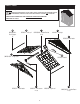
DOOR PRE-ASSEMBLY 1 Peel film from both sides of window (B). BB x13 B Lay left door (N) on flat ground with window screw attachments facing up. Place window gasket (A) into door channel, then place window (B). Cut excess gasket length. Through backside of door, secure layers with thirteen screws (BB)—start with four corner screws and then finish with remaining screws. DO NOT over tighten screws. Repeat on right door (M).
HEADER PRE-ASSEMBLY 4 5 I P 1 K K BB x2 2 BB x8 2 3 Slide roof ridge beam bracket (I) under tabs on inside peak of front header (K) and secure with two screws (BB). DO NOT over tighten screws. 6 1 Lay front header (K) on ground with lettering facing up. Place vent screen (P) into rear opening in front header (K). Secure through back of header with eight screws (BB). DO NOT over tighten screws. Repeat for rear header (L). Insert header beam (Y) into header (K). Attach using six screws (BB).
SHED ASSEMBLY – WALLS 7 Critical: When installing corners, flex corner hinges back and forth several times. This will help provide a square corner and ensure proper fit of remaining panels. Important: DO NOT flex in reverse position, as this can crack the panel. 9 1 8 D D 1 S 2 2 Align tab on bottom right side of left front corner (D) with slot on floor (S). Lower panel into slot and lock in place by sliding panel toward door opening.
Shed Assembly – Walls/Continued 11 10 1 Before proceeding, make sure corner is square (top view) where it meets the floor and that panel is flush (side view) with floor. D If not, repeat Steps 8-10 until square and flush. Top view Side view D 2 Tip left front corner (D) back to vertical position and align lower tabs on right side with slots in floor. 1 13 12 F F 2 1 2 Align tabs on bottom right side of left back corner (F) with slots along rear floor.
Shed Assembly – Walls/Continued 14 15 3 Before proceeding, make sure corner is square (top view) where it meets the floor and that panel is flush (side view) with floor. If not, repeat Steps 12–14 until square and flush. F Top view Side view F 4 Tip left back corner (F) back to vertical position and align lower tabs on left side with slots in floor. Left back corner should align and overlap previously installed side panel. 16 ecure panels with four easy bolts (R), working from S floor to roof.
Shed Assembly – Walls/Continued 17 Align tabs on bottom of back panel (G) with slots along floor. Lower back panel into slots and lock in place by sliding panel toward corner. Note: To allow back panel to overlap left back corner, tilt out slightly as you slide it into position. Note: Use a rubber mallet to “push” back panel (G) into locked position, aligned with left back corner. G 2 1 18 ecure panels with four easy bolts (R). Work from floor S to roof. DO NOT use torque wrench.
Shed Assembly/Walls (continued) 19 H J Hardware Needed R x8 Repeat Steps 17-18 for remaining panels.
SAHED SSEMBLY ASSEMBLY – DOORS – HEADERS 20 K 1 Place front header (K) over door opening and fit the two protruding support legs on left and right front corners into pockets molded in front header. Tabs on front header must be seated in header channel pocket. Secure front header using two screws (BB).
Shed Assembly – Headers/Continued 22 23 1 1 T T Z W 3 W 2 2 Z 3 Slide ridge beam (T) into front roof ridge beam bracket. Secure with one 2" hex bolt (W) and one nut (Z). Note: Alignment of ridge beam to bracket may require header panels to be pushed inwards or outwards slightly as ridge beam is slid into place. Raise ridge beam (T) up and into rear roof ridge beam bracket. Secure with one 2" hex bolt (W) and one nut (Z).
SHED ASSEMBLY – ROOF 25 O BB x8 2 FF GG FF 1 3 Before proceeding, locate and identify channels on interior side of right roof (O) and left roof (Q). Locate three underside tabs contained within each channel. Place skylight gasket (GG) into skylight (FF). Place skylight (FF) onto right roof panel (O). Secure from underside with eight screws (BB). Make sure rib on roof panel is seated fully against gasket on skylight.
Shed Assembly – Roof/Continued 27 28 O D 1 F 3 2 x6 BB 1 Slide right roof (O) down towards the outside of shed. You will hear a "snap" when engaged. Repeat other side. x4 Pull down each lower corner of roof from outside. From inside shed, attach tabs on left front corner (D) and left rear corner (F) to left roof with a screw (BB). 30 29 H J 1 1 CC x2 x6 3 DD x6 x2 x2 BB Push down the roof from outside.
Shed Assembly – Roof/Continued 31 HH BB x2 x6 Secure front roof support bracket (HH) to underside of roof using two screws (BB). Repeat step 31 for remaining roof support bracket. Shed Assembly/Doors 33 32 M M 1 x3 x3 V x3 2 2 Rotate metal hinge plates to open position. Slide one metal hinge plate over each hinge receptacle on inside of right front panel. Note: For clarity, illustration is shown with roof and ridge beam removed.
Shed Assembly – Doors/Continued 35 34 DDD 1 CCC x2 2 RR 1 1 Z x3 x2 2 2 3 X x3 Secure each metal hinge plate with one screw (X) and one nut (Z). Repeat Steps 32-34 for left door (N). Note: For clarity, illustration is shown with roof and ridge beam removed. Attach door handle (DDD) to left door with two screws (CCC) and two washers (RR). Repeat for right door. Complete.
CRAFTSMAN TEN YEAR LIMITED WARRANTY FOR TEN YEARS from the date of purchase, this product is warranted against defects in material and workmanship when product is installed, operated and maintained according to all supplied instructions. With proof of purchase, a defective part will be replaced free of charge. For warranty coverage details to obtain free part replacement, call the following toll-free number: 1-855-239-0261.
ANTES DE COMENZAR... • Consulte con sus autoridades locales para determinar qué permisos son necesarios para construir el cobertizo. Antes de iniciar la construcción del cobertizo, consulte al funcionario local encargado de los códigos de construcción para conocer los permisos necesarios o las limitaciones en la construcción. • Se requiere preparar apropiadamente el lugar de la instalación.
SEGURIDAD Y CUIDADO DEL COBERTIZO SUGERENCIAS PARA EL ARMADO • No deben guardarse artículos calientes como parrillas recientemente usadas, sopletes, etc. en el cobertizo. • No deben apoyarse artículos pesados contra las paredes ya que los paneles pueden deformarse y causar daño permanente. • Mantenga el techo sin nieve y hojas de árboles. • Este producto está hecho con materiales que soportan las condiciones de uso en exteriores.
HERRAMIENTAS NECESARIAS PARA LA INSTALACIÓN Incluido en el kit Herramienta “Easy Driver” para pernos “Easy Bolt” 010210410 PIEZAS – PAREDES Y PISO D F G 0B00342 -Panel de esquina delantero izquierdo 0B00334 - Panel de esquina trasero izquierdo 0B00344 - Panel trasero H S 0B00357 - Piso J 0B00335 - Panel de esquina trasero derecho 0B00343 - Panel de esquina delantero derecho 27
PIEZAS – PUERTAS AB 0440546A – Conjunto de la junta de la ventana x1 juego N 0B00336 – Puerta izquierda B B 0440690 – Ventana x 1 juego B DDD E M 0440631 – Perno deslizante del anillo en D 0B00337 – Puerta derecha x 1 juego 28 0463370 – Manija de la puerta x1 juego
PIEZAS – TECHO IMPORTANTE ABRA TODAS LAS CAJAS PRIMERO Y EXTIENDA LAS PIEZAS EN FORMA ORDENADA. PUEDEN HABER PIEZAS PEQUEÑAS EN CADA CAJA. CONSULTE LA LISTA DE PIEZAS INCLUIDA EN ESTE MANUAL PARA VERIFICAR QUE TODAS LAS PIEZAS ESTÉN PRESENTES. COMPLETE LA PREPARACIÓN DEL SITIO Y LA CONSTRUCCIÓN DE LA CIMENTACIÓN ANTES DE DESEMPACAR LAS PIEZAS.
TORNILLERÍA 0MP000002 - Bolsa de tornillería 0480337 Bolsa de tornillería 0480341 Bolsa de tornillería X DD Tornillo para metales de 0,25 x 0,75 pulg.
Kit del picaporte: CBMS6301 0463370 – Kit del picaporte 1 3 2 DDD Tornillería 0480370 – Bolsa de tornillería RR CCC Arandela de 0,25 pulg. x4 Tornillo de cabeza plana x4 Tornillería mostrada en tamaño real (*a menos que se especifique lo contrario). Se proporciona tornillería extra. No se usa todo.
DEL SITIO Y CONSTRUCCIÓN DE LA PLATAFORMA PREPARACIÓN Materiales NO proporcionados con el equipo del cobertizo 65002 Nota: Es necesario preparar el sitio para este cobertizo. Es Anclaje del panel de piso a la losa de cemento necesario colocar el cobertizo sobre una cimentación construida. Si no lo coloca sobre una cimentación construida, se producirá un hundimiento y el cobertizo se deformará y dañará.
DEL SITIO Y CONSTRUCCIÓN DE LA PLATAFORMA/Continuación PREPARACIÓN Materiales NO proporcionados con el equipo del cobertizo 65002 Espaciado importante en la plataforma de madera 10.48cm 30.48cm 21.6cm 82.55cm (APPROXIMADO) 30.48cm FRENTE 182.88cm • Revise todas las medidas de espaciado importantes. Lista de materiales para la plataforma de mader A C B FR EN TE D 33 Artículo Cantidad Tamaño A 1 82.5 x 182.8 x 1.9 cm (32 1/2 x 72 x 3/4 pulg.) B 4 5.1 x 15.2 x 175.
ARMADO PREVIO DE LA PUERTA 1 Despegue la película de ambos lados de la ventana (B). BB x13 B Apoye la puerta izquierda (N) sobre un suelo plano con las sujeciones para tornillos de la ventana hacia arriba. Coloque la junta de la ventana (A) en el canal de la puerta y, a continuación, coloque la ventana (B). Corte el exceso de la junta.
ARMADO PREVIO DEL DINTEL 4 5 I P 1 K K BB x2 2 BB x8 2 3 Deslice el soporte de la viga cumbrera del techo (I) debajo de las pestañas en el interior de la cima del dintel frontal (K) y asegúrelo con dos tornillos (BB). NO apriete demasiado los tornillos. 6 1 Apoye el dintel frontal (K) sobre el suelo con el lado que tiene las letras hacia arriba. Coloque la rejilla de ventilación (P) dentro de la abertura trasera del dintel frontal (K).
ARMADO DEL COBERTIZO – PAREDES 7 Paso importante: al instalar esquinas, doble las bisagras de las esquinas hacia delante y atrás varias veces. Esto ayudará a que el ángulo quede recto y asegurará la correcta colocación de los paneles restantes. Importante: NO doble en posición inversa ya que podría dañar el panel. 9 1 8 D D 1 S 2 2 Incline levemente el panel de esquina delantero izquierdo (D) hacia afuera y doble la bisagra de la esquina.
Armado del cobertizo – Paredes/Continuación 10 11 1 Antes de continuar, asegúrese de que la esquina quede en ángulo recto (vista superior) en el punto de contacto con el piso y de que el panel esté al ras (vista lateral) con el piso. D Si no lo está, repita los pasos del 8 al 10 hasta que quede en ángulo recto y al ras.
Armado del cobertizo – Paredes/Continuación 14 15 3 Antes de continuar, asegúrese de que la esquina quede en ángulo recto (vista superior) en el punto de contacto con el piso y de que el panel esté al ras (vista lateral) con el piso. F Si no lo está, repita los pasos del 12 al 14 hasta que quede en ángulo recto y al ras.
Armado del cobertizo – Paredes/Continuación 17 Alinee las lengüetas de la parte inferior del panel trasero (G) con las ranuras que están a lo largo del piso. Baje el panel trasero para introducirlo en las ranuras y trábelo haciendo deslizar el panel hacia la esquina. Nota: Para permitir que el panel trasero quede superpuesto al panel de esquina trasero izquierdo, inclínelo levemente hacia afuera a medida que lo desliza para colocarlo en la posición correcta.
Armado del cobertizo – Paredes/Continuación 19 H J Tornilleria necesaria R x8 Repita los pasos del 17 al 18 con los paneles restantes.
ARMADO SSEMBLY DEL – DOORS COBERTIZO – DINTELES 20 K 1 Coloque el dintel frontal (K) sobre la abertura de la puerta y encaje las dos patas de soporte sobresalientes de las esquinas delanteras izquierda y derecha en los receptáculos moldeados del dintel frontal. Las lengüetas del dintel frontal deben asentarse en el receptáculo acanalado del dintel. Ajuste el dintel delantero con dos tornillos (BB). Nota: No deje el dintel frontal sin apoyo hasta que la viga del dintel (O) esté asegurada (paso 23).
Armado del cobertizo–Dinteles/Continuación 23 22 1 1 T T Z W 3 W 2 2 Levante la viga cumbrera (T) e introdúzcala en el soporte de la viga cumbrera trasero del techo. Sujétela con un perno hexagonal de 2 pulg. (W) y una tuerca (Z). Nota: El alineamiento de la viga cumbrera con el soporte puede requerir empujar un poco los paneles del dintel frontal hacia dentro o hacia fuera a medida que la viga cumbrera se desliza en su lugar.
ARMADO DEL COBERTIZO – TECHO 25 O BB x8 2 FF GG FF 1 3 Antes de continuar, localizar e identificar los canales en el lado interior del techo a la derecha (O) y el techo a la izquierda (Q). Localizar tres pestañas envés contenidas dentro de cada canal. Coloque el empaque del tragaluz (GG) en el tragaluz (FF). Coloque el tragaluz (FF) en el panel de techo derecho (O). Ajuste por debajo con ocho tornillos (BB).
Armado del cobertizo – Techo/Continuación 27 28 O D 1 F 3 2 x6 BB 1 Deslice el panel de techo derecho (O) hacia abajo buscando el lado exterior del cobertizo. x4 Tire de cada esquina inferior del techo hacia abajo desde el exterior. Desde adentro del cobertizo, ajuste las pestañas del panel del extremo delantero (D) y el panel del extremo trasero (F) derecho al panel de techo con cuatro tornillos (BB). 30 29 H J 1 1 CC x2 x6 3 DD x6 x2 x2 BB Empuje hacia abajo el techo desde el exterior.
Armado del cobertizo – Techo/Continuación 31 HH BB x2 x6 Ajuste el soporte del techo (HH) al techo con dos tronillos (BB) Repita el paso 31 párrafo el resto de Soporte. Armado del cobertizo / Puertas 33 32 M M 1 x3 x3 V x3 2 2 Rote las placas de bisagra de metal a la posición abierta. Deslice una placa de bisagra de metal sobre cada receptáculo de bisagra en el interior del panel frontal derecho. Nota: Para mayor claridad, la ilustración se muestra conel techo y la viga cumbrera retirados.
Armado del cobertizo – Puertas/Continuación Ajuste cada placa de la bisagra de metal con un tornillo (X) y una tuerca (Z). 34 Repita los pasos 32 y 34 para la puerta izquierda (N). Nota: para mayor claridad, la ilustración se muestra sin el techo. 2 1 1 Z x3 X x3 35 DDD 1 CCC x2 2 RR x2 2 3 Instale la manija (DDD) en la puerta izquierda con dos tornillos (CCC) y la arandela (RR). Repita estos pasos para la puerta derecha. Terminado.
GARANTÍA LIMITADA DE DIEZ AÑOS DE CRAFTSMAN ESTE PRODUCTO ESTÁ GARANTIZADO POR DIEZ AÑOS CONTRA DEFECTOS DE MATERIALES Y MANO DE OBRA SIEMPRE QUE SU INSTALACIÓN, OPERACIÓN Y MANTENIMIENTO SE REALICEN DE ACUERDO A TODAS LAS INSTRUCCIONES SUMINISTRADAS. UNA PIEZA DEFECTUOSA SE REEMPLAZARÁ SIN COSTO ALGUNO SI SE PRESENTA EL COMPROBANTE DE COMPRA.